Introduction
ZPUE S.A has been manufacturing container substations for over 30 years. Our experience combined with highly specialised engineering knowledge has enabled us to create a wide range of solutions for the commercial power sector, industry, renewable energy sources and for specialist uses — dedicated for railway transport. Manufacturing over 3000 substations annually ensures that ZPUE S.A. is the market leader on the Polish market. Over the years, the company became a trusted and important partner supplying both European and global markets.
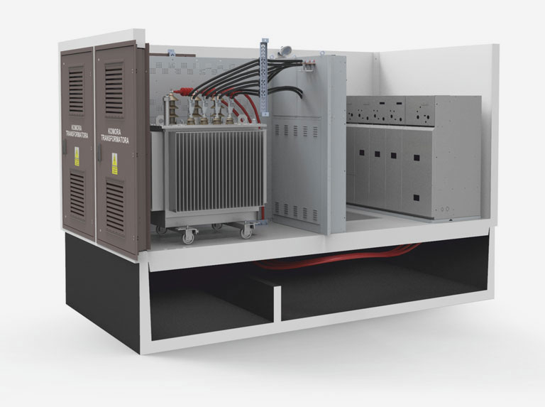
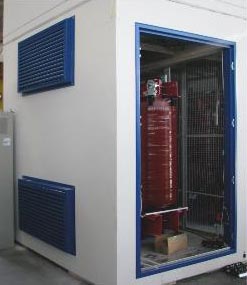
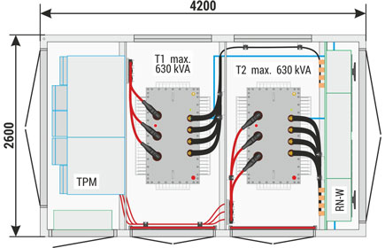
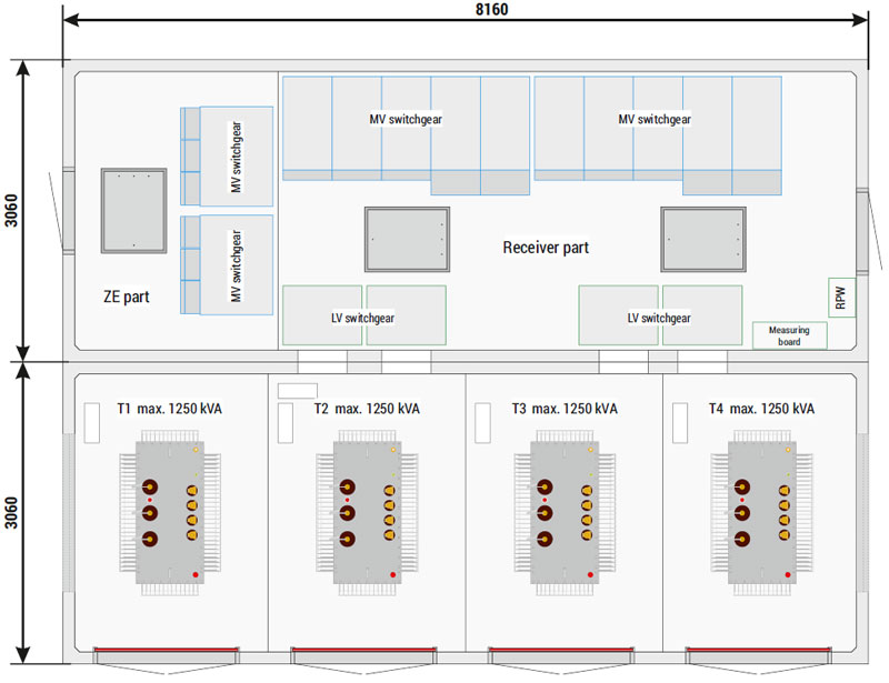
MRw-b substations in concrete enclosures with internal service corridor are prefabricated containers composed of three monolithic reinforced concrete elements, constructed with C30/37 class concrete — foundations, main structure and roof. In standard version, substation design enables the placement of hermetically sealed transformers with a power up to 1000 kVA. Our offer also includes solutions which enable installation of higher power units, even up to 4 MVA in various versions (specialised, resin and oil transformers with conservator tank).
Such solutions, due to their specific features, have to be consulted with the substation manufacturer. The transformer is installed through the transformer chamber doors or from the top, after removing the roof, and is operated after opening the doors to the transformer chamber.
Depending on the intended use, switchgears of our own manufacture are installed in the substations:
- MV — primary distribution of power: RELF, RELF 2S, RXD,
- MV — secondary distribution of power: Rotoblok, Rotoblok SF, Rotoblok VCB, TPM,
- LV - RN-W, Instal-Blok, ZR-W, Sivacon.
Others on arrangement with the manufacturer.
The aforementioned switchgears are independently installed elements of substation equipment, and they are operated, depending on the version of the substation, either from an internal corridor or from the outside, after opening the doors of a given compartment. Connections between the MV switchgear and the transformer and between the transformer and the LV switchgear are made with cables, and as option in special versions with busbar bridges or bus ducts.
Main structure
Design
The intended use of the main structure is the installation of MV and LV switchgears, remote control devices, signalling, measurement systems, transformers, power generators and other devices in accordance with the design.
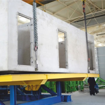
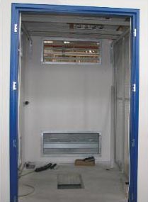
Substation enclosures with internal service corridor are manufactured as complete, self-supporting reinforced concrete structures, forming a monolithic cast of side walls with a floor slab. The main structure of the substation with external servicing is constructed as a combination of side walls with a foundation basin.
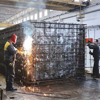
Reinforcement of the main structure (side walls and floor) is constructed as a connected whole — a cage which guarantees equipotential bonding and shields from electromagnetic radiation generated by the devices installed inside. The reinforcement mesh is bonded with substation foundation and roof.
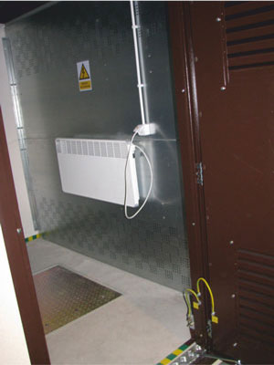
Enclosures are made of at least C30/37 concrete, which ensures high safety of operation and of members of the public, moreover guaranteeing many years of safe operation without the need to perform maintenance work. A hatch into the foundations, which also form a cable chamber, can be found in the floor of the corridor of the substation with an internal service corridor.

Wall finish
The internal wall surface is covered with white plaster or paint for decorative purposes. External walls in standard design are covered with decorative plaster. The colour sets and references to the RAL colour palette are presented below.
It is possible to construct the substation in accordance with individual architectural requirements, taking into account all available methods and materials for the finishing of concrete surfaces. Types of plaster (e.g. silicone, mosaic, colours or materials such as clinker, brick effect etc.) not included in this list are available on arrangement with the manufacturer. It should be however kept in mind that this will result in a longer order delivery time and an individual technical and price offer.
| Primary plaster colours | Colour similar to | |
| TEXAS TX2 | RAL 1015 | |
| ATLANTIC AT2 | RAL 7047 | |
| White | RAL 9010 | |
| Optional plaster colours | Colour similar to | |
| BALI BL2 | RAL 6019 | |
| ETNA ET2 | RAL 7044 | |
| FLORIDA FL2 | RAL 1015 | |
| MADEIRA MD1 | RAL 1015 | |
| POLAR PL1 | RAL 7047 | |
| SAVANNE SV4 | RAL 1001 | |
NOTE!
The colours shown in the table may differ from reality.
When selecting colours always compare with the original colour chart.
Substation joinery
All metal elements installed on the outside of the substation are made from powder painted aluminium, with RAL palette colours. The list below contains the basic colour scheme for doors and ventilation louvres. Other materials and colour schemes are available on arrangement with the manufacturer. It should be however kept in mind that this will result in a longer order delivery time and an individual technical and price offer.
| Colour | ||
| RAL 3003 | RAL 7032 | RAL 8004 |
| RAL 8017 | RAL 6001 | RAL 8007 |
| RAL 5010 | RAL 7024 | RAL 9010 |
NOTE!
The colours shown in the table may differ from reality.
When selecting colours always compare with the original colour chart.
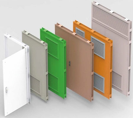
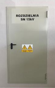
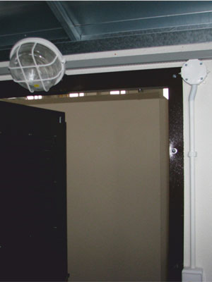
Doors
Depending on intended use, the substation doors are single leaf (e.g. switchgear operation corridor) or double leaf (e.g. transformer chamber), and their size is adapted to the dimensions of the installed devices. They may be constructed either as solid doors or with ventilation louvres, and the double-shell construction prevents the condensation of water inside the substation. The basic protection rating is IP 23D or IP43 (on arrangement with the manufacturer it is possible to construct doors in another version).
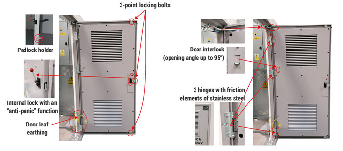
All doors open outwards (opening angle up to 95o — other angles on request), have a mechanism for locking in an open position and covered internal hinges with friction elements made of stainless steel. The doors have three-point locking bolts, locked with a lock adapted to the installation of cylinders with integrated protection against weather conditions. Additionally the doors can be independently equipped with a padlock attachment. For the substation with an internal service corridor, the door lock enables opening the doors from inside regardless of the position of the external handle, which prevents the locking of an employee inside the substation.
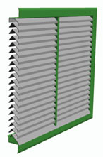
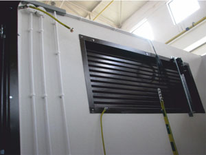
Ventilation louvres
The ventilation louvres (supply and exhaust) installed in transformer substations ensure a correct temperature is maintained inside transformer chambers and ensure ventilation of rooms where power engineering devices are installed.
Due to the ingenious, patented labyrinth design with high capacity, gravity ventilation is possible even for transformers with powers up to 1250 kVA while keeping the louvre dimensions to a minimum. This solution minimizes the operational costs of transformer substations due to elimination of the need to use intake or exhaust fans (the costs of electricity, servicing and spare parts, among others).
However, individual requirements concerning transformer substation ventilation should be taken into account, e.g. in case of installation of transformers or devices which generate significant amounts of heat, gravity ventilation must be supplemented with intake and exhaust fans. Their efficiency and location is selected by experienced engineers supported by IT tools.
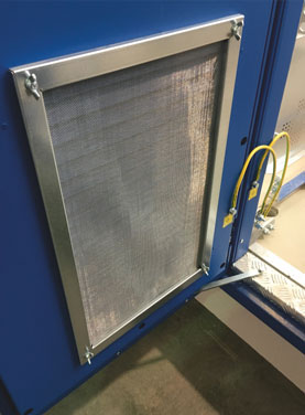
In standard version ventilation louvres provide an IP 23D or IP 43 protection rating. Louvres with an IP 43 protection rating have internal protection against the ingress of insects.
In locations exposed to significant dust levels (e.g. industrial plants) it is possible to use ventilation louvres with filter cartridges. In this case it should be remembered, however, that an installation equipped with filter cartridges has to be fan-assisted in order to ensure appropriate exchange of air and requires regular cleaning or replacement of filter cartridges.
Location of the station for fire protection
The location of the station should be implemented in accordance with the ordinance of the minister of infrastructure of April 12, 2002 on the technical conditions to be met by buildings and their location (Journal of Laws of June 15, 2002, No. 75, item 690, as amended) or local regulations.
Individual cases of station location should be considered individually and consulted with ZPUE S.A. or with authorized services (fire safety opinion issued by a fire protection expert).
Fire protection
In order to ensure the highest possible level of fire safety and to limit the possibility of a fire or its possible effects in transformer stations, passive protection measures are used, such as: fire separation walls and ceilings, cut-off dampers or fire doors.
The basic means of fire protection of most transformer stations manufactured by ZPUE is the special structure of external walls or partition walls and ceilings, ensuring the separation class at the REI 120 level, where the individual values mean respectively: R - fire resistance (structure strength), E - fire integrity (flame penetration or gases through the surface), I - fire insulation (surface heating), 120 - time expressed in minutes for the criteria listed. The quality of the walls has been confirmed by the Fire Testing Department of the Institute of Building Technology and by independent fire protection experts.
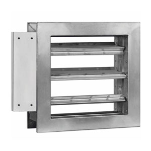
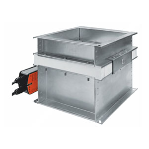
In order to ensure the appropriate class of fire separation of walls with ventilation louvers and ceilings with exhaust fans installed, they use cut-off dampers with protection levels, e.g. EI 60 or EIS 120. During a fire, they ensure fire resistance and prevent the spread of fire, smoke and fire gases both to the rest of the building not affected by the fire, as well as outside the station.
Optionally, in the walls of the station where the door is located, and it is necessary to ensure the appropriate fire resistance class by the enclosure, doors are installed that ensure the fire separation class EI 60 or EI 120. When selecting the class of closures or fire barriers, the total area of the enclosure on the wall should be taken into account. or the ceiling of the station.
Exemplary producer: https://www.mercor.com.pl/pl/produkty/wentylacja-pożarowa/klapy-przeciwpożarowe/
Internal systems
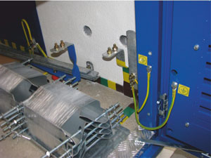
Earthing system
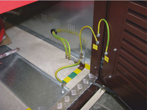
In order to ensure a high level of safety of the operating personnel and members of the public, all substations are equipped with a complete, internal earthing system. The system is constructed in accordance with the legal regulations in force, and also based on technical standards of power distribution companies and individual guidelines of the customers.
The main earthing busbar may be constructed from zinc-coated steel, copper or copper-coated flat bars. All conducting elements of substation equipment (switchgear enclosures, doors, ventilation louvres, support structures etc.) are permanently connected to the main earthing busbar. The type and manner of connection is selected individually, in accordance with the intended use.
The concrete enclosure itself provides additional, natural insulation. It guarantees safety even when internal connections to the external earthing systems are damaged.
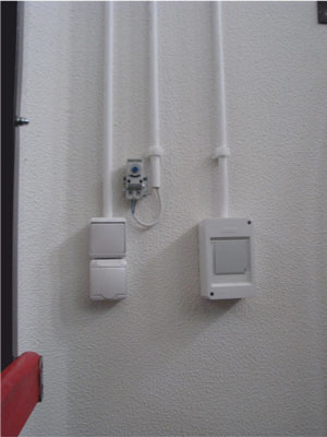
Auxiliary power system
The auxiliary power system is a standard equipment of transformer substations. It consists of an auxiliary switchgear with protection of electrical circuits, lighting system, and a set of sockets and switches necessary for its correct operation.
The location of lighting fixtures, adapted to the installation of energy-saving light sources, is designed in order to ensure an appropriate minimum lighting level required for the operation of technical devices, in accordance with standards and regulations on operational safety. Optionally the substation may be equipped with an individual or central emergency lighting system connected to substation automation.
Depending on the customer's requirements and on the type of devices installed in the substation, as well as local conditions, substations may be equipped with a heating, ventilation or air conditioning system. Control is fully automatic, and temperature or humidity sensors are placed in such a manner as to ensure optimum operating conditions.
Foundations
Design
Foundation of a substation with an internal service corridor, similarly to the main structure, is constructed as complete, self-supporting reinforced concrete structure (monolithic cast of side walls with a floor slab) using at least C30/37 class concrete. The foundations of transformer substations with external servicing and MV cable connection boxes in concrete enclosures have a similar design.
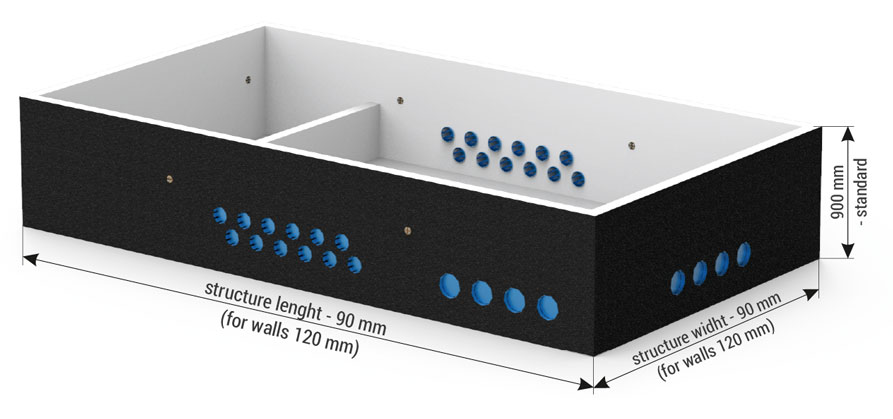
Foundations have separate compartments, one containing an oil sump, which can contain at least 100% or more of the volume of oil from the transformer installed in the substation.
Due to the special formulation, the foundation is waterproof and oilproof, which effectively prevents water infiltration and leaking of oil outside the transformer substation in case of a transformer failure. Additionally, it is also protected with a waterproofing sealing on the outside, to secure it against the destructive impact of groundwater.
In addition to the oil sump, the foundations of transformer substations and cable connection boxes also have a cable compartment with integrated MV and LV cable entries (constructed at the foundation prefabrication stage) in an amount enabling the connection of all incoming and outgoing cables over a full range of conductor cross-sections from 25 to 300 mm2. Cable entries are adapted to the installation of sealing inserts. Their number and type should be established at the ordering stage.
The foundation also has cable entries for the feeding and sealing of cables or hoops of the internal earthing system.
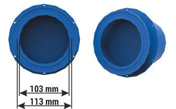
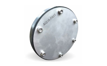
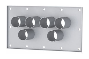
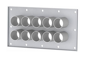
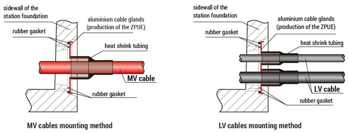
MV and LV cable entries and seals
A system of APP type closed membrane cable entries and APW type sealing inserts in the “mechanical compression” technology.
| APP-100 | |
| diameter to the membrane | 113 mm |
| diameter behind the membrane | 103 mm |
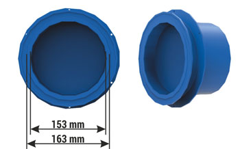
| APP-150 | |
| diameter to the membrane | 163 mm |
| diameter behind the membrane | 153 mm |
| APW1-100/30/U | |
| range of diameters | 1 x 24 - 63 mm |
| cable cross-sections | 1 x 50 - 240 mm2 |

| APW3-150/30/3xU | |
| range of diameters | 3 x 30 - 41 mm |
| cable cross-sections | 3 x 70 - 300 mm2 |
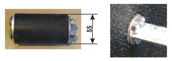
| APWZ-100 |
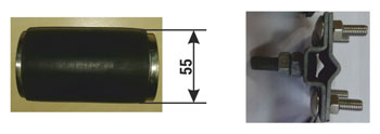
| APWZ-150 |
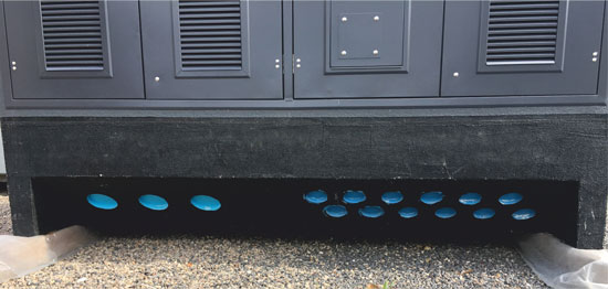
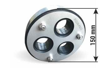
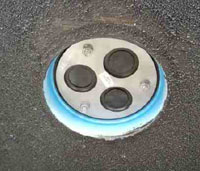
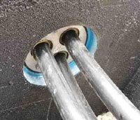
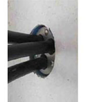
View of installed cable entries
NOTE!
On arrangement with the manufacturer it is possible to use different systems of cable entries and seals.
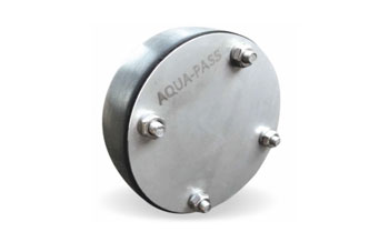
Plate type cable entries
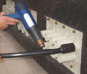
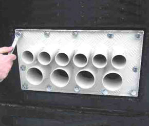
NOTE!
On arrangement with the manufacturer it is possible to use different systems of cable entries and seals.
Sealing of the earthing system
NOTE!
On arrangement with the manufacturer it is possible to use different systems of cable entries and seals.
Roofs
Concrete roof — basic equipment
In standard versions, transformer substations are equipped with concrete roofs, which protect the devices installed inside against external elements. They are constructed similarly to the enclosures, with C30/37 reinforced concrete. They are prepared for connecting to the reinforcement of the main structure, crating a uniform cage providing shielding against electromagnetic radiation which may be generated by devices installed within the substation. The external part of the roof is protected with coats of paint resistant to weather conditions and UV radiation.
- Slope of approx ~ 2-3o,
- Height above the substation structure level - 130 mm,
- Resistance to mechanical loads - 2500 N/m2.
| Colour | ||
| RAL 9010 | RAL 5010 | RAL 8004 |
| RAL 7032 | RAL 6001 | RAL 8007 |
| RAL 3003 | RAL 7024 | RAL 8017 |
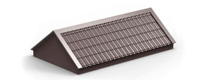
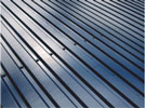
Metal roofs (architectural covers) — optional equipment — examples
Metal roofs are used mainly in locations where a reference to existing buildings has to be made for architectural purposes. The roof frame is constructed of structural steel protected against corrosion.
There are many versions of coverings available, e.g. sheet metal roofing tiles, ceramic roofing tiles or asphalt shingle. Due to a wide range of manufactured transformer substation enclosures, both the height (above the level of main structure), and the slope of the roof will depend on the substation dimensions, which should be taken into account when preparing construction designs. Metal roofs may be placed as architectural covers over a concrete roof, in which case their height is specified combined with the concrete roof, or as an independent, self-supporting structure.
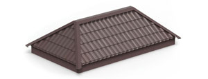
Hip (cottage) roofs
Slope: 20-25o, height: 700-800 mm
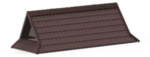
Gable roofs
Slope: 20-25o, height: 700-800 mm
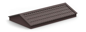
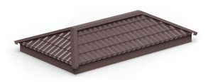
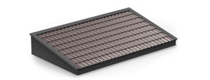
Shed roofs
Slope: 5-12o, height: 400-800 mm
Hip (cottage) roofs
Slope: 30-40o, height: 1200 mm
Gable roofs
Slope: 30-40o, height: 1200 mm
Zakopane style roofs
Slope: 45-50o, height: 1850 - 2500 mm
NOTE!
On arrangement with the manufacturer it is possible to construct a roof according to an individual design.
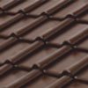
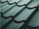
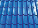
Types of roof coverings — examples
| Roofing sheet or troughed sheet | Colour | Ceramic tile |
Asphalt shingle |
Colour |
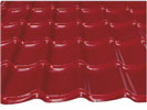 |
BTX 2710 (red) |  |
 |
Red |
 |
BTX 6701 (dark bronze) RAL 8017 (dark bronze) |
 |
 |
Bronze |
 |
BTX 7700 (graphite/black)) BTX 2610 (graphite/gray) |
 |
 |
Graphite |
 |
BTX 4702 (dark green) | 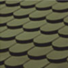 |
 |
Green |
 |
RAL 5010 (blue) | 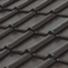 |
 |
Black |
 |
RAL 9010 (white) |  |
 |
Melange |
| Finishing / structure: BTX - coarse matt RAL — gloss | ||||
NOTE!
The catalogue contains examples of roof coverings, both materials and colours.
Presented colours may differ from reality. When selecting colours always compare with the original colour chart.
On arrangement with the manufacturer it is possible to optionally construct a roof covering according to an individual design.
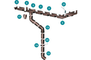
Roof gutters — optional equipment — examples
Both concrete and metal roofs may be optionally equipped with gutter systems for collection of rainwater. They may be constructed of both PVC and steel. They are designed individually for a given roof section. Initial assembly is performed in a factory, and final assembly at the intended location of the substation, in order to avoid damage in transport.

| Colour | |
| RAL 8019 | RAL 7016 |
| RAL 9010 | RAL 6009 |
| RAL 9017 | RAL 8004 |
Example manufacturer: http://gamrat.pl/oferta/systemy-rynnowe
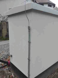
Lightning protection
Cable stations and connectors equipped with a particularly valuable and significant from the point of view of safety energy infrastructure, such as control and protection automation, discrete electronics or power electronics, should be equipped with a lightning protection system, whose task is to protect the facility against lightning strikes and safely discharge its energy the shortest way to the ground. Installation should be carried out in accordance with applicable normative regulations, as well as on the basis of technical standards of distribution companies and individual customer guidelines.
A typical lightning protection system consists of the following elements:
- vertical and horizontal air terminals installed on the roof, usually made of galvanized steel wire, stainless steel, copper and ALMgSI aluminum alloy, the diameter of which has been unified to 8 mm,
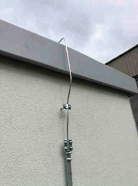
- discharge wires connecting the spikes and earth electrodes, made of the same materials as are used for air terminals. Discharge pipes can also be made of steel strip. They are mounted with brackets about 2 cm from the facade of the building or in special lightning rods connected to the earth electrode with a test clamp that can be placed in a test (control and measurement) box,
- earth electrodes, most often in the form of a horizontal, closed rim around the station, made of galvanized, copper or copper flat steel bars, optionally in the form of driven vertical bars. It is advisable to use the elements of the so-called natural earth electrodes that are, for example, components of the reinforcement of the building foundation.

Substation naming system
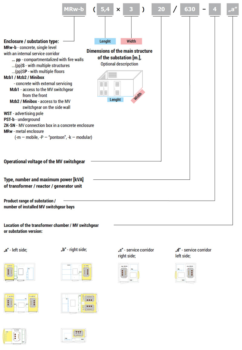
Substation naming system - examples
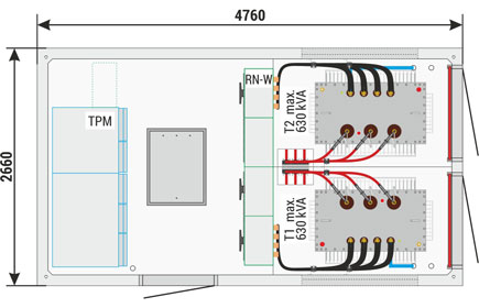
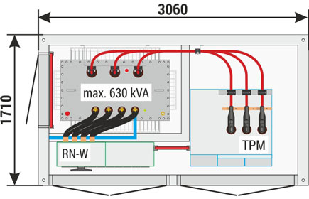
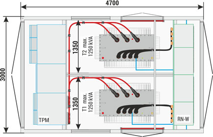
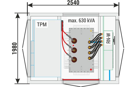
List of manufactured enclosures
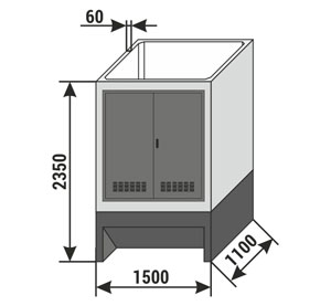
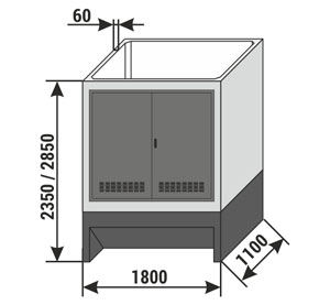
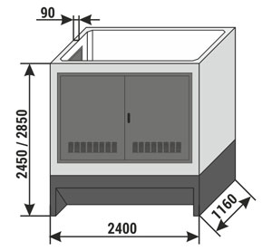
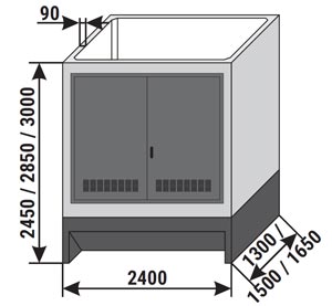
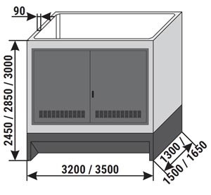
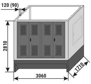
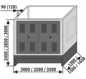
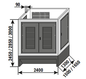
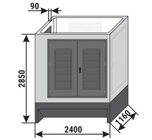
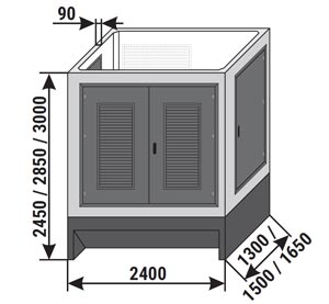
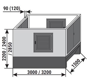
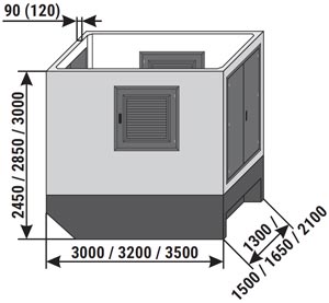
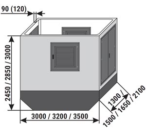
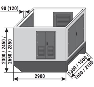
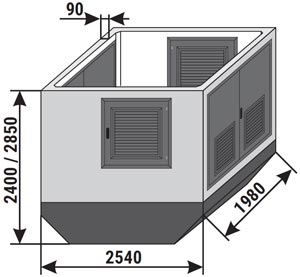
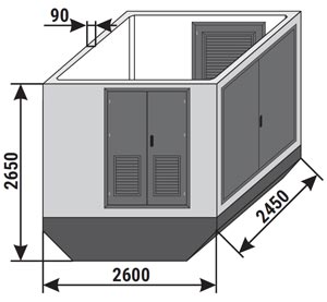
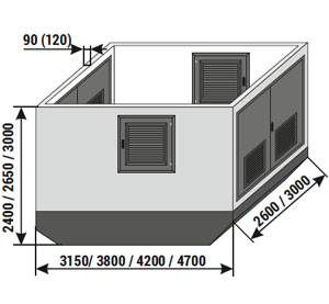
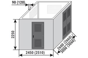
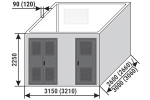
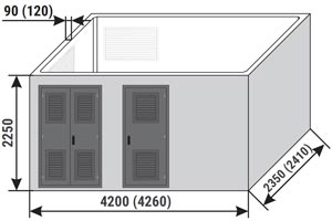
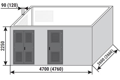

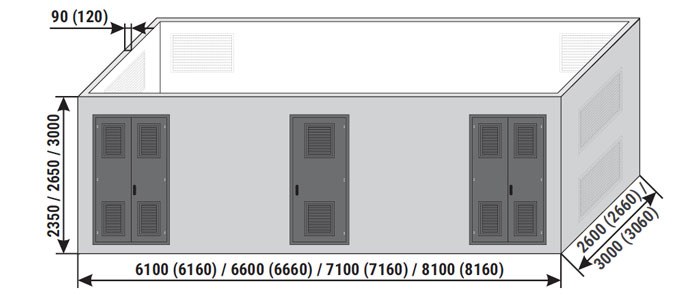
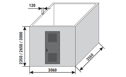
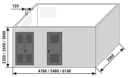
NOTE!
The views present standard heights of enclosures. It is possible to construct the main structure of the substation up to a height of 3500 mm, however such solutions should be consulted every time with the manufacturer.
Transport
ZPUE S.A. has its own fleet, as one of few companies manufacturing prefabricated container substations. Provision of transport services is intended to lower the costs of transporting ZPUE S.A. equipment and to improve the quality of customer service. We offer a transport set with a gross vehicle weight rating of 70 tonnes, which can carry even up to 50 tonnes of cargo. Our road tractors are the latest generation models which meet Euro 6 exhaust emissions (standard for allowed exhaust emissions for new vehicles sold in the European Union).
Example of transformer substation transport
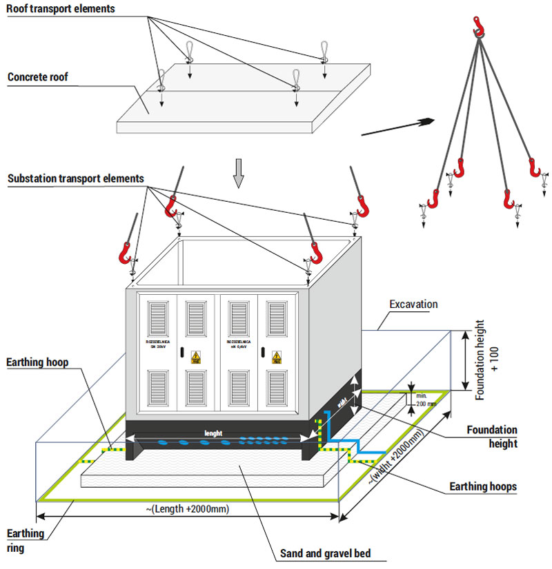
MRw-b type substation placement
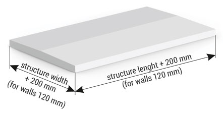
All works related to substation placement should be performed in accordance with a technical design drawn up on the basis of current standards and industry regulations and local guidelines, taking into account geotechnical conditions. The guidelines specified below should be treated as examples, which should be verified every time using data at the given substation location. The first stage of substation placement is excavation of a trench. External earthing of the substation in the form of an earthing ring (or other, in accordance with local earthing requirements) should be placed in the prepared trench.
Under the foundation a sand and gravel bed with a final thickness (after compaction) of at least 20 cm should be constructed. The thickness of the sand and gravel bed should be adapted to the local water and soil conditions and the local freezing zone. The surface of the sand and gravel bed should be level in the substation placement plane, and the quality of bed preparation in the excavation confirmed in the acceptance report. The foundation basin of the substation should be placed in the prepared location. Place a single layer of sealing tape on the upper part of the foundation basin. When placing the sealing tape, make sure that it does not overlap and does not stretch. This could cause damage or deformation.
Place the main structure of the substation over the foundation prepared in this manner, and then place the roof over it. The next stage is covering the foundation, performed by stages, with 20 cm layers of compacted filtering soil. Special care should be taken when covering the excavation at the site of contact with foundation wall, not to break the applied water insulation of vertical surfaces. Pay special care in the location where cables enter the cable entries, since mechanical compaction may cause damage to entries or cables.
It is important that the walls of the foundation basin protrude by no less than 10 cm above the final ground level. Placement in complex and complicated water and soil conditions, in mining areas and post-mining areas is recommended after a separate, individual design is prepared by a certified design body, with required geological and engineering documentation, under supervision performed by duly authorised personnel.
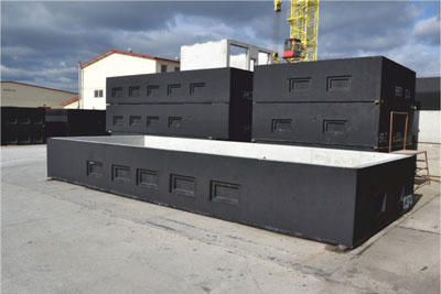
Example placement of a substation with an internal service corridor
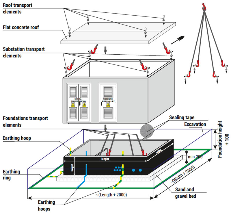
NOTE!
The placement diagram above, due to the method of raising the main structure, is dedicated to substations with dimensions not exceeding: length: 5460; width: 3060; height: 2350.
MRw-bS type substation placement
The placement of an MRw-bS type substation is performed in the same manner as for an MRw-b type substation, with the difference that after the sand and gravel bed is made, a reinforced concrete stabilisation slab is poured, which prevents slab faulting and non-uniform settling of individual substations. Recommended minimum thickness of reinforced concrete slab 20 cm, C16/20 class concrete, minimum reinforcement with meshes at the top and bottom using ribbed bars Ø10/Ø12 mm top/bottom, spaced no more than 25 cm apart, made of AIIIN steel (e.g. RB 500W, 20G2VY-b — weldable steel), top and bottom reinforcement shifted in relation to each other by half of mesh size.
The actual and target thickness of the stabilising slab and the used reinforcement should be verified with structural calculations, taking into account load-bearing capacity at the placement site, taking into account the weight of the complete substation with equipment.
Example placement of a substation with external servicing
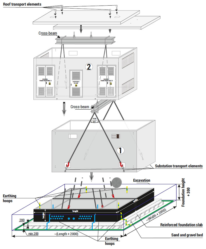
NOTE!
Placement of a substation with dimensions exceeding: length: 5460; width: 3060; height: 2350 should be performed in the same manner as on the figure above (elements used to raise the substation should be screwed into threaded sleeves prepared in the lower part of side walls or in the floor, depending on the construction version).
Placement of a substation with external servicing, Mzb type
A substation placement site for an Mzb type substation with external servicing should be prepared in the same manner as for an MRw-b type substation.
The difference will stem only from the substation's design. In case of MRw-b type substations, the foundation and the main structure form two independent elements, whereas in case of an Mzb type substation with external servicing these elements form a single unit (foundation is combined with the main structure), which should be placed in the prepared excavation. Then a transformer is inserted from above (before the roof is attached), and in the last stage the roof is placed on the substation's main structure.