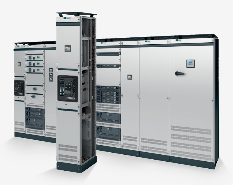
Advantages
- Maximum system safety thanks to standard modules with construction verification.
- Maximum personnel safety thanks to the electric arc resistant locking system.
- High-quality industrial design that perfectly matches the modern style of the rooms.
- Space-saving erection surfaces, from 400 x 500 mm.
- Variable, top or rear position of the main busbars.
- Combinations of different installation systems in one cell.
- Flexible adaptation of the internal separation form to different requirements.
- Simple subsequent changes of door opening direction thanks to universal hinges.
- The ventilation system characterized by a high degree of performance and maintenance advantages.
- Cable / busbar connections from the top, bottom or rear.
Features
| Circuit breaker system | Universal Installation system | Fixed mounted system |
3NJ6 in-ilne system | 3NJ4 in-ilne system | Reactive power compensation | |
| Mounting systems | Fixed-mounted design Withdrawable design |
Fixed-mounted design with compartment doors Plug in 3NJ6 in-line design Withdrawable unit design, plug-in unit design |
Fixed-mounted design with front covers |
Plug-in 3NJ6 in-line design | Fixed-mounted design | Fixed-mounted design |
| Functions | Incoming feeder Outgoing feeder Coupler |
Cable feeders Motor feeders |
Cable feeders | Cable feeders | Cable feeders | Central reactive power compensation |
| Rated current In | Up to 6300 A | Up to 630 A Up to 250 kW |
Up to 630 A | Up to 630 A | Up to 630 A | Non-chocked up to 600 kvar Chocked up to 500 kvar |
| Connection position | Front & Rear | Front & Rear | Front | Front | Front | Front |
| Cell width (mm) | 400/600/800/1000/1400 | 600*/1000/1200 | 1000/1200 | 1000/1200 | 600/800/1000 | 800 |
| Internal separation | Form 1, 2b, 3a, 4b, 4 type 7 (BS) | Form 2b, 3b, 4a, 4b, 4 type 7 (BS) | Form 1, 2b, 3b, 4a, 4b | Form 1, 3b, 4b | Form 1, 2b | Form 1, 2b |
| Main busbar position | Rear/Top | Rear/Top * not for 3NJ6 |
Rear/Top | Rear/Top | Rear | Rear/Top/Without |
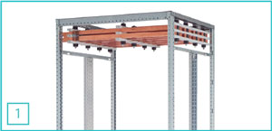 1. Position of the main busbars at the top up to 6300 A.
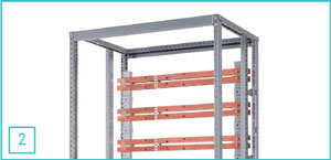 2. Variable rear busbar position up to 7000 A (top and/or bottom).
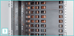 3. Plug-in busbar system with contact protection, cover (IP 20B) for quick and easy replacement of fuse switch disconnectors.
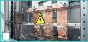 4. Optimal connection conditions in the busbar connection compartment.
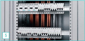 5. Multi-profile busbars allow easy assembly of modular installation devices.
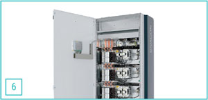 6. Cells with reactive power compensation with design verification according to PN-EN 61439 reduce transmission losses.
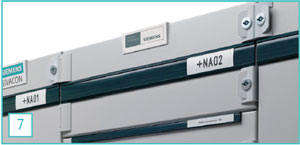 7. Overview of power distribution thanks to a standardized labeling system for sections and feeders.
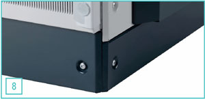 8. A modern look with design elements like the side panel and optionally extendable base.
Circuit breaker system
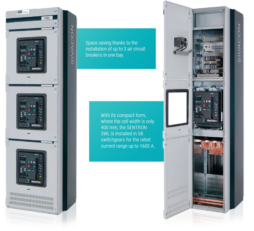
Supply, outgoing and coupling cells are equipped with SENTRON® 3WL air circuit breakers in stationary and withdrawable technology, or alternatively, with SENTRON 3VL compact circuit breakers. Because many receivers are generally installed on the line downstream these circuit breakers, they are extremely important in ensuring long-term operational safety of the switchgear and personnel safety. SIVACON compactly and safely meets the above requirements through the components of the circuit breaker system.
Universal installation system
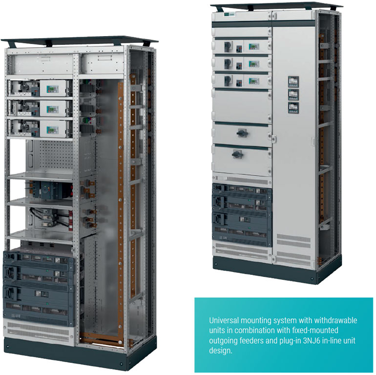
Because many applications require a space-optimized assembly of the power distribution switchgears, different installation systems must be integrated in one cell. For such applications, the universal SIVACON assembly system ensures high performance, safety and diversity due to the combination of outgoing feeders in withdrawable, plug-in, stationary techniques and outgoing feeders in the 3NJ6 pin strip technology. What’s more, the withdrawable technique provides significant flexibility with often varying requirements such as variable motor parameters or connecting new receivers. In addition, this technique also meets ergonomic requirements and facilitates simple and safe operation, as well as short set-up times for maximum system availability.
Busbar
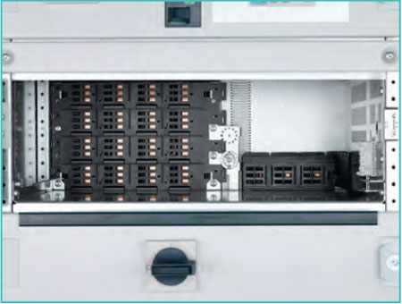 Rear plug-in busbar system
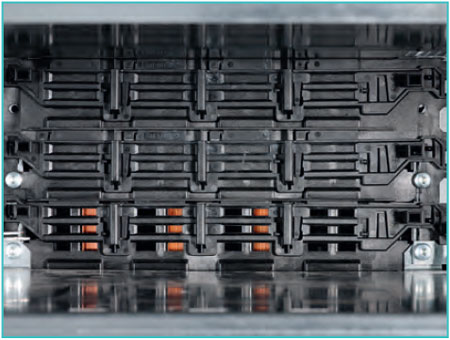 Optional with shutter
Plug-in busbar system
The plug-in busbar system is located at the back of the cell. It provides touch protection without any additional covers for active parts.
- Installation resistant to electric arc.
- Phase separation.
- 3- and 4-pole technique.
- Touch protection (IP20B).
- Connection holes in the 50 mm modular grid for mounting standard withdrawable units.
Optional
- Double-action shutters for standard withdrawable units.
SIVACON withdrawable units
SIVACON withdrawable units ensure safety in operation and maintenance
- Maximum system security thanks to standard modules with type testing.
- Identical operation of all withdrawable unit sizes.
- Sizes of withdrawable units matched to power parameters.
- All parts are installed inside the withdrawable unit - protection against accidental damage.
- Integrated protection against switching errors for all withdrawable units.
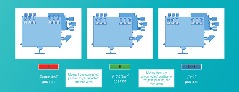
- Clear indication of the position of the withdrawable units.
- Separate operation of the main switch and withdrawable unit position.
- „Test” and „disconnected” position with the door closed without reducing the degree of protection of the switchgear.
- Lockable in „diconnected” position.
- Patented slow wearing contact system of withdrawable unit ensuring long life.
- Optional mechanical coding of withdrawable units to avoid mistake with withdrawable units of the same size.
- Hinged panel for mounting control and signaling devices.
- Standard withdrawable units for cable and motor outgoing feeders up to 630 A.
- Fuse and circuit breaker technology.
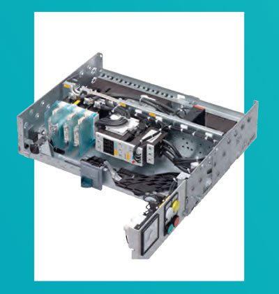 Hinged panel for mounting control and signalling devices in order to perform service works during work.
Standard withdrawable units
- Height 100 mm to 700 mm up to 18 (withdrawable units in one cell).
Optionally to standard withdrawable units a similar plug-in design
- Supply and outgoing contact systems permanently attached to the plug-in segment.
- „Connected” and „diconnected” position (no „test” position).
- Integrated protection against switching errors.
More details can be found in the catalog card below in the "download" tab.
Universal Installation System
Individual Combination Options (Fixed-Mounted Design with compartment doors, Plug-In 3NJ6 In-Line Design).
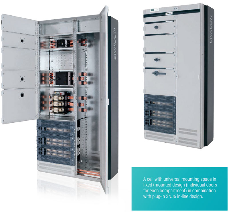
Many applications require different solutions suitable for different protection systems, therefore different installation systems must be integrated in one cell. For such applications, the universal SIVACON mounting system ensures high performance, safety and flexibility due to the combination of outgoing feeders in fixed-mounted design and in plug-in 3NJ6 in-line system.
More details can be found in the catalog card below in the "download" tab.
Fixed-Mounted System with Front Covers
Wide integration options
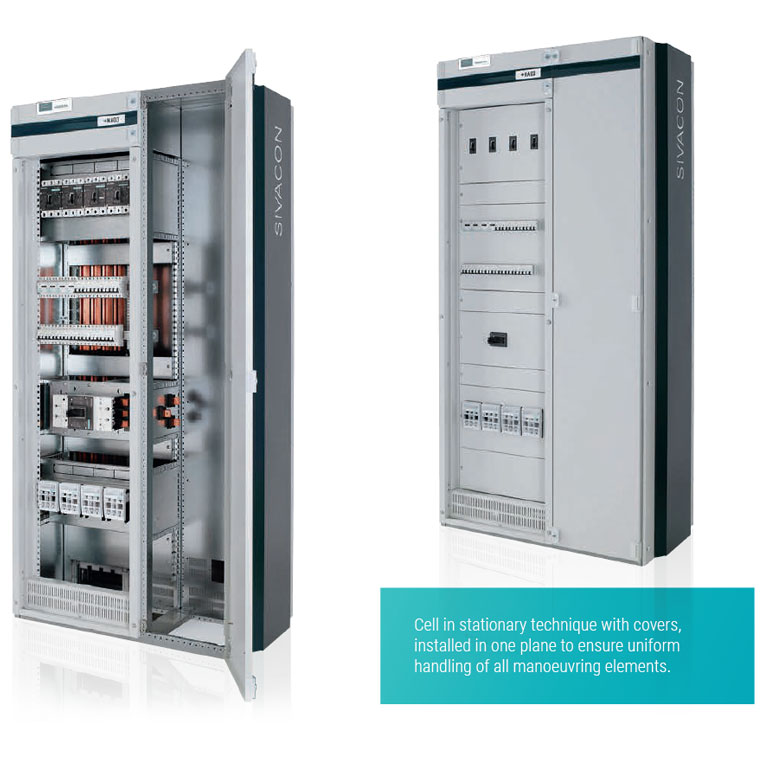
- High system safety due to standard modules with type testing.
- Cable feeders up to 630 A with and without current measurement.
- Modularly combined functional groups.
- The innovative quick fastening system allows easy mounting of the cover.
- Hinged frame with covers for easier supervision and ease of maintenance.
- Expansion modules when functional separation of compartments is required (up to form 4b).
- Front control panel with covers, optionally with full cell door height.
- Doors with an inspection window enabling integration with modern interiors.
- Cable connection compartment 400 mm or 600 mm width.
Some applications do not require component replacement under operating conditions or short downtimes are allowed. In these cases, the SIVACON system in fixed-mounted system covers ensures maximum performance, safety and flexibility.
More details can be found in the catalog card below in the "download" tab.
Fixed-Mounted 3NJ4 In-Line System
Efficient assembly
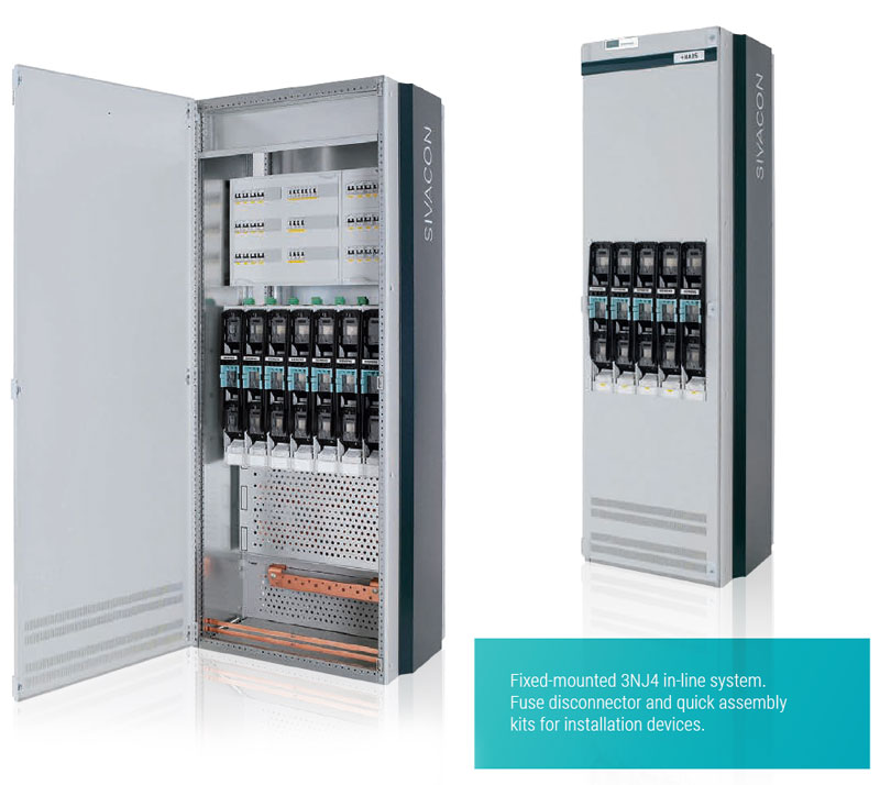
- High system safety due to standard modules with type testing.
- Cable feeders up to 630 A with and without current measurement.
- Possibility of installing up to 14 feeders in one cell.
- Fuse replacement with the receiver switched off.
- Door optionally with a cut-out or without a cut-out.
- Optional installation of quick assembly kits or mounting plates for individual equipment.
- Cell widths: 600 mm and 800 mm.
The cells designed for cable feeders in fixed-mounted system are equipped with fuse switch disconnectors, whose compact and modular design ensures optimal performance, especially in the case of applications in infrastructure.
Plug-In 3NJ6 In-Line System
Quick modernization
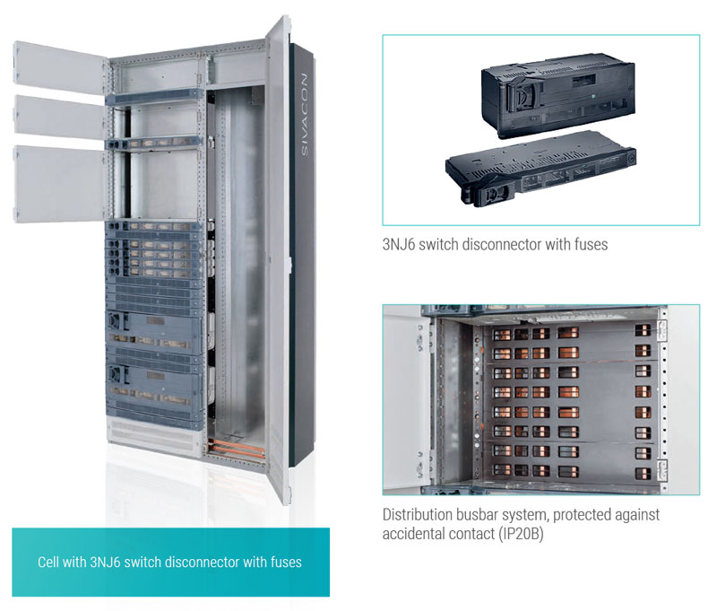
- High system safety due to standard modules with type testing.
- Switch disconnector with double break for cable feeders up to 630 A.
- Integrated replaceable current transformer.
- Manual or motor drive with stored energy mechanism.
- Possibility of upgrading the accessories by the user.
- High packing density - up to 35 feeders in one cell.
- Cable connection compartment: 400 mm or 600 mm width.
- Degree of protection up to IP41.
- Replacement of outgoing feeders possible with powered switchgear busbars.
Strip-type disconnectors with a plug-in power connector are an economical alternative to the withdrawable system and provide simple and quick modernization, as well as - thanks to their modularity - measurement activities in working conditions. For such applications, SIVACON guarantees high efficiency, safety and flexibility.
Frame and enclosure
Embedded protection
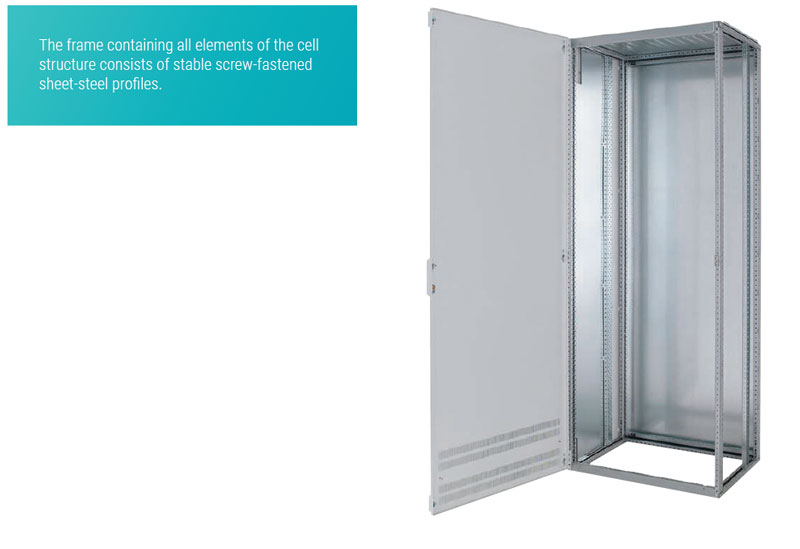
- Rows of holes in the form of a raster placed along the entire height and width of the frame with a spacing of 25 mm, which allow individual configuration.
- Patented lock and hinge system to ensure staff safety.
- Doors with individual or central locking.
- Universal hinge system that allows easy change of the direction of door opening.
- Door opening angle up to 125° (180° for freestanding assembly).
- Doors with a two-position lock or with a rotary lever lock.
- Top plates with pressure relief system.
- Frame heights: optionally 2000 mm or 2200 mm.
- Additional base 100 mm or 200 mm.
- Standard separation partitions between cells.
Surface treatment
- Cubicle parts, bases, back panels and bottom plates galvanized with the use of Sendzimir method.
- Easy and safe access to distribution busbars.
- Doors, enclosures and covers painted / powder coated in light grey RAL 7035; construction elements in blue-green.
Material
The frame and enclosure are made of sheet steel with the following thicknesses:
- Frame, base 2.5 mm.
- Covers: 2.0 mm.
- Doors: 2.0 mm.
Technical data
| Technical data | |||
| Norms and standards | Low Voltage Switchgear and Control gear |
PN-EN 61439-2 DIN EN 61439-2 (VDE 0660 part 600-2) |
|
| Testing of response to internal faults (arcing faults) |
IEC 61641, VDE 0660 part 500, Suplement 2 | ||
| Protection against electric shock | DIN EN 50274, VDE 0660 part 514 | ||
| Rated insulation voltage (Ui) | Main circuit | 1000 V | |
| Rated operating voltage (Ue) | Main circuit | Up to 690 V | |
| Direct and indirect distances between active elements |
Rated impulse withstand voltage Uimp | 8 kV | |
| Overvoltage category | III | ||
| Pollution degree rating | 3 | ||
| Busbar bridges (3-pole and 4-pole) | Main busbar horizontal | Rated Current | Up to 7000 A |
| Reated peak withstand current (Ipk) | Up to 330 kA | ||
| Rated short-time withstand current (Icw) | Up to 150 kA | ||
| Vertical busbar bridges in switching technology |
Rated Current | Up to 6300 A | |
| Reated peak withstand current (Ipk) | Up to 220 kA | ||
| Rated short-time withstand current (Icw) | Up to 100 kA | ||
| Vertical busbar bridges in the universal assembly technology and stationary technique |
Rated Current | Up to 1600 A | |
| Reated peak withstand current (Ipk) | Up to 143 kA | ||
| Rated short-time withstand current (Icw) | Up to 65 kA* | ||
| Vertical busbar bridges in 3NJ4 fuse strip technology |
Rated Current | Up to 1600 A | |
| Rated short-time withstand current (Icw) | Up to 50 kA | ||
| Vertical busbar bridges in 3NJ6 plug strip technology |
Rated Current | Up to 2100 A | |
| Reated peak withstand current (Ipk) | Up to 110 kA | ||
| Rated short-time withstand current (Icw) | Up to 50 kA* | ||
| Rated currents of devices | 3WL / 3VL circuit breakers | 3WL / 3VL circuit breakers | Up to 6300 A |
| Cable outgoing feeders | Cable outgoing feeders | Up to 630 A | |
| Motor outgoing feeders | Motor outgoing feeders | Up to 250 kW | |
| Internal separation | Form 1 to 4b | IEC 61439-2, Section 8.101, VDE 0660 Part 600-2, 8.101 |
|
| Type 7 for form 4 | BS EN 61439-2 | ||
| Surface treatment | (Coating according to DIN 43656) | ||
| Frames and bases | Sendzimir-galvanized | ||
| Doors | Powder-coated | ||
| Side panels | Powder-coated | ||
| Rear panels, top plates | Sendzimir-galvanized | ||
| Ventilated roof | Powder-coated | ||
| Standard colour of powder coated elements (coating thickness 100 ± 25 um) |
RAL 7035, light gray Design parts: blue green basic |
||
| Degree of protection IP | In accordane with IEC 60529, EN 60529 | IP30, IP31, IP40, IP41, IP42, IP54 | |
| Dimensions | Preferred dimensions in accordance with DIN 41488 |
Height (without base) | 2000, 2200 mm |
| Width | 200, 350, 400, 600, 800, 850, 1000, 1200 mm |
||
| Depth (wall-mounted, freestanding) | 500, 600, 800 mm | ||
| Depth (double-front) | 1000, 1200 mm | ||
| * Icc = 100 kA | |||

