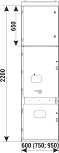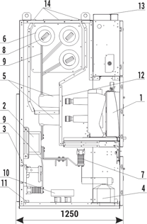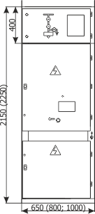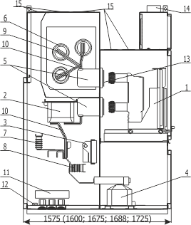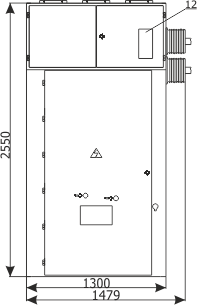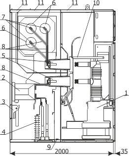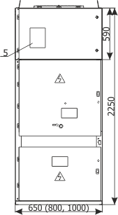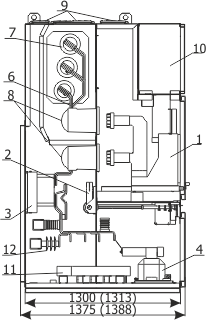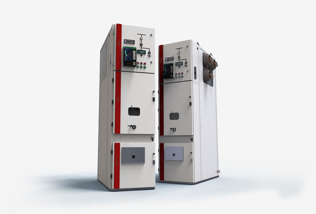
The catalogue presents RELF and RELF ex type medium voltage switchgear:
- air insulated (AIS),
- in metal enclosure,
- metal - clad,
- withdrawable,
- with a single busbar,
- for a rated voltage up to 36 kV,
- for indoor use.
Characteristics of the switchgear
- The switchgear is designed to operate in distribution transformer stations in industrial sites which generate, distribute and consume electricity.
- The switchgear complies with the requirements of (PN-EN) IEC 62271-200, (PN-EN) IEC 62271-1 and GOST, provides IP4X degree of protection. It is designed to work in normal conditions defined by the (PN-EN) IEC 62271-1 standard.
- The switchgear is designed to assure safety during normal operation, inspection and handling.
- The switchgear cubicle is of a frameless construction, made of galvanized steel sheets and fixed with rivets. It is in the form of a multicompartment cabinet, with walls and partitions that form a self-supporting structure.
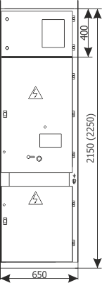
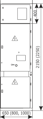
- There are four compartments in the switchgear bay: cable connections, busbars, withdrawable main device and LV auxiliary circuits compartment.
- The cabinet's door and side shields of the outermost bays (back shields for wall mounted cubicles) are powder coated.
Types of bays
The switchgear may be composed of various functional units.
These are:
- incoming/outgoing feeder bays,
- bus coupler bays,
- bus riser bays,
- metering bays with the possibility of busbars earthing,
- switch disconnector bay,
- others - acc. to arrangements.
The withdrawable module of the switchgear may be equipped with a circuit breaker, contactor, sectionalizer or a set of fused voltage transformers. The withdrawable module may be placed in the positions of: service, test/disconnection and separation.
Characteristic and advantages
- air insulated,
- optional electrical drives for all switches - fully automated switchgear,
- Loss of Service Continuity category - LSC2B (three MV compartments),
- possibility of equipping with current and voltage sensors - environmentally friendly solution,
- IAC AFLR internal arc classification,
- interlocks and protections against performing incorrect switching operations,
- wall-standing or free-standing options,
- optional thermal imaging measurements of cable connections or temperature monitoring system,
- possibility of expanding the switchgear with additional bays,
- possibility of bay replacement without the need to draw aside the adjacent bays,
- ease of operation.
The switchgear ensures high safety of operation through:
- internal arc resistance of the switchgear enclosure,
- improper switching operations interlocks and door locks and interlocks,
- racking the withdrawable module with doors closed,
- the use of compartments with PM class partitions,
- the possibility of visual control of switching operations through inspection windows,
- the use of blow-out flaps which limit the pressure increase in case of an internal arcing fault,
- optional gas exhausting duct - discharges gases outside of the switching station room,
- bay voltage indication system.
Basic technical data
Compliance with standards
The RELF type switchgear meets the requirements of the following standards:
- (PN-EN) IEC 62271-1 - „High-voltage switchgear and controlgear. Common specifications”,
- (PN-EN) IEC 62271-200 - „High-voltage switchgear and controlgear. AC metal-enclosed switchgear and controlgear for rated voltages above 1 kV and up to and including 52 kV”.
The switchgear is certified by appropriate accredited bodies.
| Electrical data: | ||||||
| RELF | RELF ex | |||||
| Rated voltage | [kV] | 12 | 17,5 | 24 | 36 | 12 / 17,5 |
| Main busbars and incoming feeder rated continuous current | [A] | 630 - 4000 | 630 - 2500 | 630 - 2500 | 630 - 1600 | 630 - 2500 |
| Rated power-frequency withstand voltage | [kV] | 28 | 38 | 50 | 95; 85,5(5min) /95(1min) |
28; 38 |
| Rated lightning impulse withstand voltage | [kV] | 75 | 95 | 125 | 190 | 75; 95 |
| Rated frequency | [Hz] | 50 | ||||
| Rated short-time withstand current | [kA/3s] | up to 40 | up to 31,5 | up to 31,5 | up to 25 (up to 31,5/1s) |
up to 25 |
| Rated peak withstand current | [kA] | up to 100 | up to 80 | up to 80 | 63/80 | up to 63 |
| Withstand for internal arcing fault | [kA] | up to 31,5/1s up to 40/0,5s |
up to 31,5/1s | up to 31,5/1s | up to 25/1s | up to 25/1s |
| Degree of protection | up to IP4X (IP3X for 4000A) | |||||
| Cubicle height | [mm] | 22001) | 22001) | 22501) | 2550 | 2250 |
| Cubicle width | [mm] | 600-950 (650-1000) | 600-950 (800-1000) |
800/1000 | 1300 | 650/800/1000 |
| Cubicle depth | [mm] | 1250/1575/1675 | 1250/1575/ 1675 |
1600/1688/1725 | 2035 | 1375/1388 |
| Compliance with standards | (PN-EN) IEC 62271-200; (PN-EN) IEC 62271-1 | |||||
| Service conditions: | |
| Ambient temperature | Relative humidity |
|
- peak short-time+40oC
|
- highest day average95%
|
|
- highest day average +35oC
|
- highest month average90%
|
|
- highest annual average +20oC
|
- highest day average vapour pressure2,2kPa
|
|
- lowest long-term-5oC
|
- highest month average vapour pressure1,8kPa
|
| Atmosphere at the place of installation |
no significant contamination with salt, vapour, dust,
smoke, flammable or corrosive gasses and lack of icing, frosting and dewing |
| Installation altitude |
up to 1000 m. a.s.l.2)
|
| Vibrations |
vibrations caused by external factors
or earthquakes negligible |
Note:
- - bay height may differ due to construction and height of the LV compartment. Details should be arranged with the manufacturer,
- - if the switchgear installation altitude is higher than 1000 m. a.s.l. the switchgear insulation level should be corrected in accordance with the standard.
Switchgear design
Design
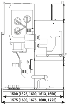
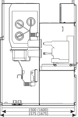
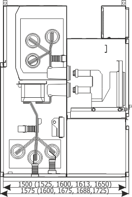
The RELF switchgear bay is designed as a cabinet divided into four separate functional compartments:
- busbars compartment (medium voltage circuits),
- main device compartment (medium voltage circuits),
- cable compartment (medium voltage circuits),
- auxiliary circuits LV compartment (low voltage circuits).
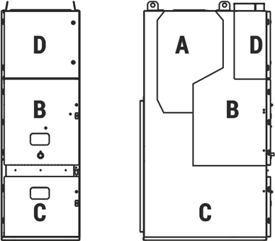
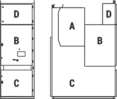
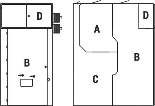
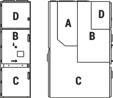
The switchgear cubicle is constructed of bent steel sheets, riveted together, without welding. Walls and partitions create a selfsupporting structure. A corrosion-resistant zinc-coated sheet is used for the construction of cabinets.
High-strength round-head steel rivets were used to connect structural elements. Functional compartments are limited by internal vertical and horizontal partitions. The internal partitions are attached to side walls, reinforcing and stabilising the entire enclosure. Additionally, two-part side covers made of painted sheet are bolted to the external walls of the outer bays of the switchgear.
The switchgear may be constructed as free-standing or wall-standing. The front belt between the doors of the main device compartment and the doors to the cable connection compartment and the horizontal partition between these compartments are removable (does not apply to the RELF 36 version), which significantly facilitates maintenance and installations.
Internal partitions allow safe access to main device compartment and cable connection compartment, even when the primary busbars are live.
In accordance with the LSC (Loss of Service Continuity) category, the switchgear meets the criteria of LSC2B. This condition is met by switchgear with three MV compartments and the withdrawable module placed in the test/disconnection position.
The MV circuits compartment doors are made of powder coated sheet. Doors use hinges and bolts which can stand up to explosiontype loads. The hinges allow opening the doors by approximately 135º (170º in case of RELF 36). Upper and lower edges of the doors were reinforced by appropriately shaped and welded reinforcing profiles.
Doors to the main device compartment are equipped with an inspection window used for visual control of the position of the withdrawable module and switching operations.
The design of the doors allows the mechanical opening of the circuit breaker in operating position with the doors closed.
Blow-out flaps
All MV compartments have blow-out duct openings in their top zone, closed with flaps. Their task is to discharge any pressure created inside the compartment as a result of an internal arc fault.
A sudden increase of pressure inside the switchgear compartment breaks the plastic bolts and opens the flaps, which may activate limit switches installed at the roof of the switchgear. Limit switches activated by the flaps being opened send an impulse which trips the main circuit breaker. This allows limiting the effects of an arc fault generated inside the cubicle compartment.
Withdrawable module
The withdrawable module is a unit composed of a racking system, and depending on the bay function: circuit breaker, contactor, set of fused voltage transformers, or a sectionalizer. The racking system performs the physical connection of the withdrawable module with the switchgear bay. It's stationary part is connected with the bay by interlocking on both sides in guide rail cut-outs.
The moving part of the racking system is shifted between the service position and the test/disconnection position using a drive screw operated manually with a crank, or with an electric drive, while the doors are closed. The service and test/disconnection position is signalled by position indicators, after the module reaches an appropriate position.
The shutters in the main device compartment are discussed in the main device compartment description.
Cubicle compartments
The busbars compartment is inaccessible during normal operation. For maintenance purposes access to busbars is possible from the top of the cabinet, after removing the blow-out flaps (or from the main device compartment side after removing the partition - for RELF 36). It is closed on both sides with gland plates made of non-magnetic steel sheet or insulating material. These plates prevent damage from spreading to adjacent bays in case of an electric arc in the busbars compartment.
Gland plates and bushings insulators are elements which support the busbars. Outgoing busbars branch off from the main busbars and enter the spouts which separate the busbar compartment from the main device compartment.
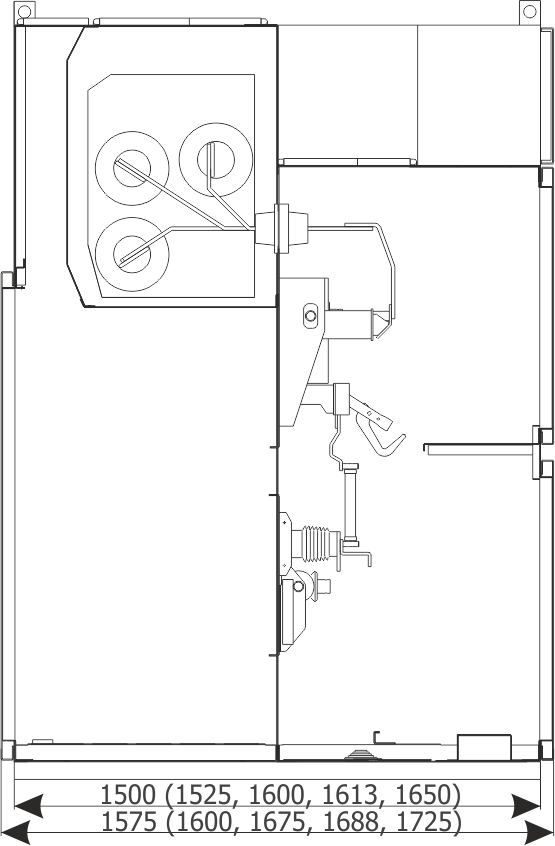
The main device compartment is available after its doors are open in an interlock-controlled mode. The main device compartment contains the withdrawable module and all the elements necessary for its operation with the cubicle bay, such as: withdrawable module guide rails, shutters, spouts with fixed contacts, door interlock and earthing switch interlock elements and auxiliary circuits socket/plug.
The spouts are installed in the partition separating the main device compartment from the cable connection compartment and busbars compartment. Fixed contacts and outgoing busbars are set in the spouts.
The shutters with an unlocking mechanism are installed in the main device compartment. Their task is to separate the compartment space from fixed contacts, which may be live when the withdrawable module is in the test/disconnection or separation position. A safe insulation space remains between the contacts and the closed shutters.
Racking in the withdrawable module from the test/disconnection position to the operating position causes the shutters to slide apart and the fixed contacts to be exposed, allowing the circuit breaker tulip contacts to connect.
Mechanical indicators of the circuit breaker position and drive charging state are visible through the inspection window.
The cable connection compartment is designed to connect cables or busbars and is accessible after opening only the front doors (wall-standing version) or front and rear doors (free-standing version) in an interlock-controlled mode1). This compartment contains current transformers, an earthing switch, and depending on operational requirements, optionally: voltage transformers2), earth fault transformers and surge arresters.
Voltage transformers are installed in the front part of the connection compartment (not in RELF 36kV).
The earthing switch is equipped with a manual drive, or a manual and motor drive. Its status is indicated by the position indicator.
The compartment bottom is closed by a split floor cover, which also acts as a cable gland plate. Openings in the plate are covered with rubber cable glands. Cable clamps installed on supports are used to fasten the cables.
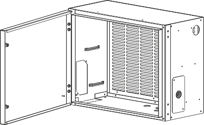
The auxiliary circuits LV compartment is constructed in the form of a control cubicle and is completely separated from the high voltage zone of the switchgear. The cubicle has its own sheet metal enclosure and is prefabricated independently of the high power part of the switchgear. It may be equipped with devices on a separate station, and then attached to the switchgear cabinet.
The cubicle is intended for the installation of: protection relays and IEDs, instrumentation & control devices and automation system elements.
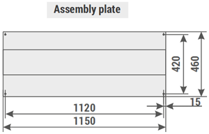
It is installed on the roof of the switchgear, above the switching device compartment. In its bottom, top and side walls a series of openings are made for lead and cable glands and cable trays. These openings are covered by plates, in which holes can be made according to design needs. An assembly plate fixed to the rear wall of the LV cubicle was designed for the installation of devices. The devices may be also fixed on the side walls. On arrangement with the manufacturer, the cubicle design may be adapted to individual needs of the customer and of the design.
Main busbars
A single, three-phase busbar system is used in the switchgear. The busbars are installed in a separate compartment.
The main busbars are supported by distribution busbars which come out of the spouts and on insulating bushings installed in the side partitions.
Busbar cross-sections are selected in accordance with the rated current of the switchgear.
Insulating elements
The switchgear uses epoxy resin insulators. In the connection compartment the busbars are supported by post insulators.
For supporting the main busbars and passing them through switchgear bays, bushings are used, set in the gland plates of the bay side walls.
The passages through the partition between the switching device compartment and the busbars compartment and the connection compartment are provided by spouts.
Protective earthing
An earthing conductor is placed in every cabinet, in the form of a copper busbar with a cross-section of 40x10 mm, placed at the bottom of the cabinet. These busbars are bridged between the cabinets, creating an earthing conduit. The conduit is terminated by terminals on the left and right side of the switchgear, used to connect it to the facility's earthing system.
Cable connections
The connection compartments are designed for entry of single- or multi-core MV cables.
1) in the RELF 36 version the connection compartment is accessible after opening the cabinet doors and removing the partition on the side of the switching device compartment.
2) does not apply to the RELF 36 version.
System of interlocks and protections
The switchgear may be equipped with a range of standard and additional mechanical and electrical interlocks, intended to improve operational safety:
Mechanical interlocks:
- prevent racking the withdrawable module in or out of the operating position when the circuit breaker is closed,
- allow the closing and opening of the circuit breaker only in the operating and test/disconnection positions,
- allow the closing of the earthing switch only in the test/disconnection or separation position of the withdrawable module,
- prevent racking in the withdrawable module from the test/disconnection position to the operating position if the earthing switch is closed,
- prevent opening the switching device compartment door if the withdrawable module is in the operating or intermediate position,
- prevent opening the cable compartment door (or bay door in the RELF 36 version) if the earthing switch is open,
- allow changing the position of withdrawable module only when it is locked in a bay,
- prevent racking in the withdrawable module from the test/disconnection position to the operating position if the compartment door is open (optional),
- prevent racking in the withdrawable module from the test/disconnection position to the operating position until the circuit breaker control circuits supply plug is connected to the circuit breaker (option - contact the manufacturer),
- prevent racking in the withdrawable module from the test/disconnection position to the separation position until the circuit breaker control circuits supply plug is set to the separation position (option - contact the manufacturer),
- a servicing truck for the transporting of withdrawable modules may be equipped with a secure bay coupling mechanism, which prevents changing the position of the racking truck even when its wheels are unlocked (optional),
- a servicing truck for the transporting of withdrawable modules may be constructed in a way that allows moving the withdrawable module from the truck to the bay only after mechanical coupling of the truck with the bay (optional),
- a servicing truck for the transporting of withdrawable modules may be constructed in a way that allows uncoupling the truck from the bay only after the withdrawable module is locked in the bay or in the truck,
- allow locking the drive of shutters which cover the fixed contacts in the switching device compartment (optional),
- allow locking access to the earthing switch operating mechanism latch.
The cable connection compartment door lock is constructed to allow closing and locking the door after it has been opened and the earthing switch has been set to the OPEN (de-earthed) position with the doors open. Afterwards, the interlock prevents opening the door again until the next earthing operation.
On arrangement with the manufacturer it is possible to use additional key and padlock interlocks.
Electrical interlocks:
- prevent closing the circuit breaker if its auxiliary circuits are not powered; only mechanical opening of the circuit breaker is possible (optional),
- prevent racking the withdrawable module to the operating position without power supply to the control circuits (optional),
- prevent access to the earthing switch drive when closing of the earthing switch requires additional conditions (for example, main busbar earthing switch can be closed only when the withdrawable modules in the particular section are in the test/disconnection position),
- prevent access to the withdrawable module drive when racking the module requires additional conditions.
Interlocks are always designed to fit to a particular project.
On arrangement with the switchgear's manufacturer, it is possible to install additional interlocks, which operate based on limiting switches and electromagnetic locks.
The door design allows them to be unlocked in an emergency and the compartment to be accessed when needed.
Switchgear equipment
Switching devices
The switchgear may be equipped as standard with VB-4 (ZPUE), SION (Siemens), VD4 (ABB), HVX (Schneider Electric) vacuum circuit breakers; HD4 (АВВ) gas insulated circuit breakers; 3TM (Siemens), ConVac (ABB) contactors. Other devices may be used on arrangement with the switchgear manufacturer. A fast earthing switch type US1 (ZPUE) or EK6 (ABB) is used to provide the highest level of safety. As standard, NAL/NALF (ABB) type devices are used as switch disconnectors.
Metering instrumentation
Transformers by different manufacturers are used for metering purposes. Bay voltage indication utilizes capacitive insulators or transformers with voltage dividers and a voltage indicator.
Protection devices
The switchgear can be equipped with low voltage devices by any manufacturer, according to the individual needs of the customer. It is also possible to install any digital protection relay, or IED.
An internal arc protection system can be installed in the switchgear. The systems sense the internal arc by detecting the flash and an additional voltage or current criteria inside the protected switchgear. When these two events occur simultaneously, the system is activated and a circuit breaker tripping impulse is sent.
Diagrams of primary and auxiliary circuits, switchgear automation
Primary circuits
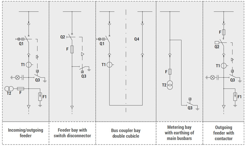
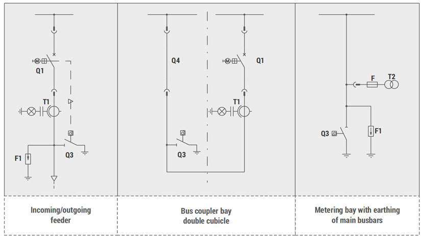
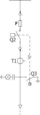
Structural diagrams of primary circuit examples are shown on Figure 2. The connection compartment's equipment varies depending on the bay type. Alternative solutions to the ones presented can be implemented on arrangement with the manufacturer.
Auxiliary circuits
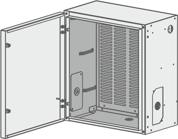
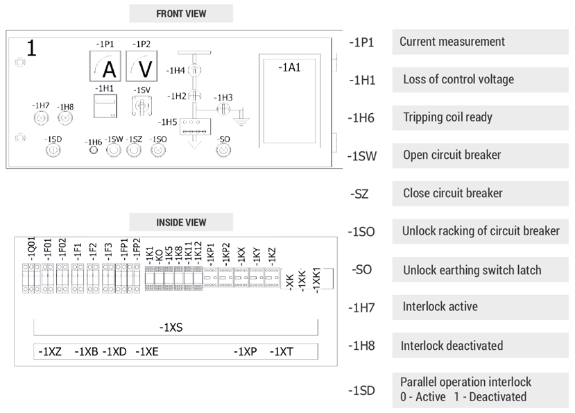
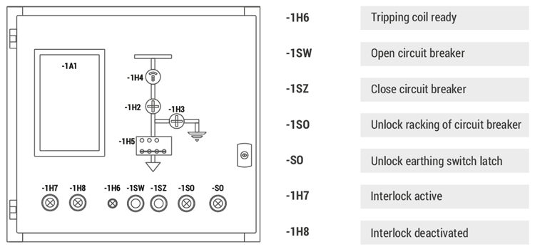
LV auxiliary circuits consist of: protection relays, metering, control, automation and signalling systems. An auxiliary circuits compartment located at the front, top part of the switchgear cabinet is intended for the devices of these circuits.
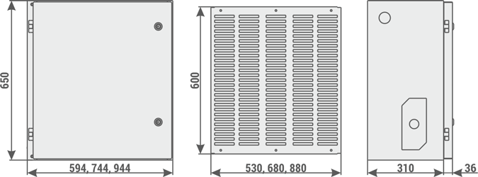
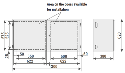
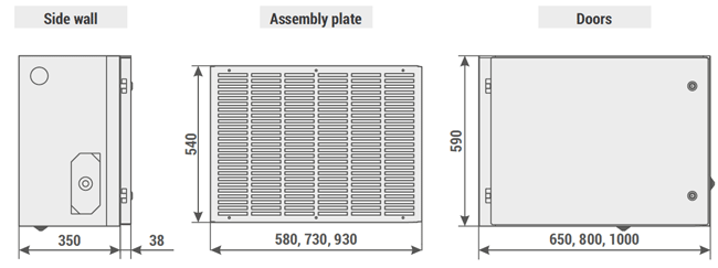
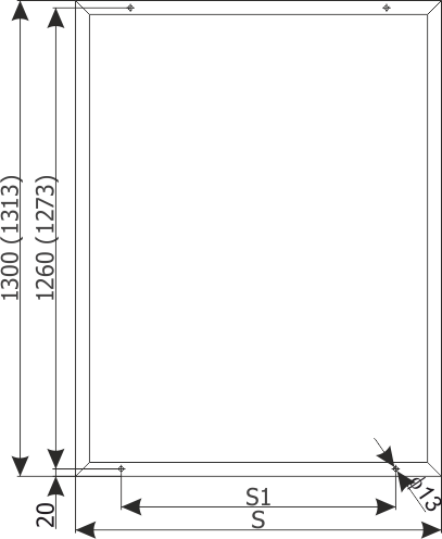
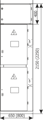
The dimensions of the compartment and example arrangement of devices are presented on figures 3 and 4.
Diagrams of example internal and assembly connections for primary and auxiliary devices for a typical switchgear equipment can be obtained by contacting the switchgear manufacturer.
Switchgear automation
The switchgear is designed to operate in SCADA systems. With this goal in mind it is equipped with digital protection relays (with possible digital communication) and automation systems. The switchgear can then operate in master control systems and automated control systems.
Switchgear packaging, transport and installation
Packaging
Three packaging methods are used for RELF type switchgears:
- standard packaging - the switchgear cubicle is placed on a pallet and wrapped with shrink wrap,
- in boxes - switchgear cubicles are packaged as described above and put into boxes,
- maritime transport packaging - switchgear cubicles with inserted moisture absorbing material are placed in barrier plastic sheet bags, which are evacuated. The switchgears protected in this manner are transported on pallets or in boxes.
Transport
Switchgears are transported as single cubicles. Transport in the room and to the room in which the switchgear is to be installed can be done with a crane, forklift, or on rollers.
For crane transport, the cubicle is equipped with transport lugs. The angle of lifting ropes should not exceed 120°. Attaching the lifting ropes directly to the cabinet structure is prohibited. To enable lifting the switchgear with a forklift, the cubicle is placed on a transport pallet.
During the transport and installation of the switchgear cubicle, special care should be taken to not to damage the paintwork and steel sheet enclosures.
Main devices, such as circuit breakers, contactors, withdrawable modules, and LV devices sensitive to vibrations, are transported separately in the manufacturers' original packages.
Switchgear installation
The manner of switchgear placement and external cable and busbar connections depend on the design of the facility where it will be installed. These connections should be performed according to the instructions established during arrangements with the switchgear manufacturer. The switchgears can be placed directly on concrete floor, on foundation frame attached to the floor, or on a steel or concrete structure of the facility.
Regardless of the type of foundation, switchgears must be placed exactly horizontally and attached to the foundation.
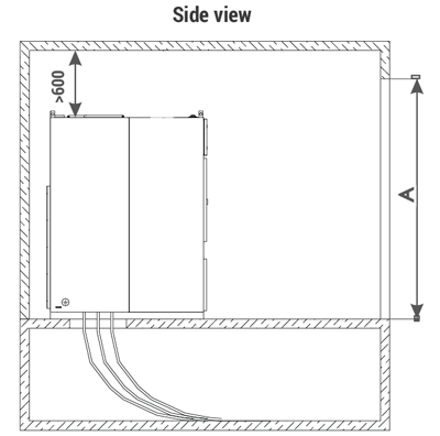
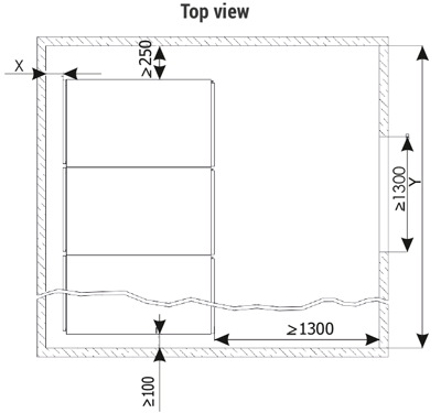
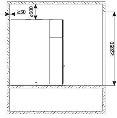
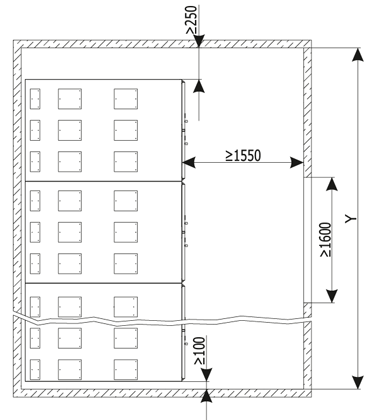
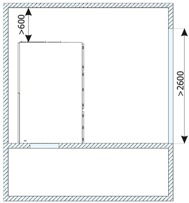
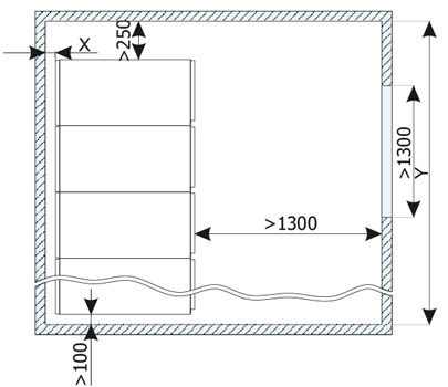
The placement of the switchgear in a room is presented on figures 5a,b,c. The X dimension depends on the manner in which the switchgear is placed:
- for a wall-mounted placement the recommended distance is at least 100 mm,
- for free-standing placement, full opening of the rear doors requires an X not less than the width of the widest bay of the switchgear.
Recommended minimum distance from closed safety flaps on the switchgear roof to the room ceiling: 600 mm.
Due to the switchgear installation technology it is recommended that the Y dimension of the room be at least 1000 mm higher than the total length of the switchgear.
The recommended minimum room doors height A for the switchgear should be higher by at least 350 mm than the height of the switchgear.
On figure 6a,b,c example dimensions for holes to be made in the floor for cable entries are shown. They should be treated as demonstrations, and their exact location agreed upon when ordering the switchgear.
On figure 7a,b the load bearing/installation frame of the RELF and RELFex switchgear is shown, with holes for attaching the switchgears to the foundation, on figure 8 - methods for attaching the switchgears to the foundation.
Standard equipment delivered with the switchgear
Standard equipment delivered with the switchgear
Each switchgear is equipped with:
- fasteners for connecting all the units together,
- withdrawable module racking crank,
- earthing switch drive crank,
- withdrawable module transport cart (with the exception of RELF 36),
- cabinet key doors.
Documents delivered with the switchgear:
- declaration of conformity,
- switchgear manual,
- operation and maintenance manuals and warranty cards for the used devices,
- as-built documentation for the switchgear,
- warranty card.
Drawings
List of figures
- Figure 1a - RELF bay equipment - version I
- Figure 1b - RELF bay equipment - version II
- Figure 1c - RELF 36 bay equipment
- Figure 1d - RELF ex bay equipment
- Figure 2a - Structural diagrams of RELF and RELF ex primary circuits
- Figure 2b - Structural diagrams of RELF 36 primary circuits
- Figure 3a - RELF bay auxiliary circuits compartment - version I
- Figure 3b - RELF bay auxiliary circuits compartment - version II
- Figure 3c - RELF 36 bay auxiliary circuits compartment
- Figure 3d - RELF ex bay auxiliary circuits compartment
- Figure 4a - Examples of device layout in the RELF bays auxiliary circuits compartment
- Figure 4b - Examples of device layout in the RELF ex bays auxiliary circuits compartment
- Figure 5a - Placement of the RELF switchgear
- Figure 5b - Placement of the RELF 36 switchgear
- Figure 5c - Placement of the RELF ex switchgear
- Figure 6a - Example dimensions of the cubicle bases and floor holes for RELF bays
- Figure 6b - Example dimensions of the cubicle bases and floor holes for RELF 36 bays
- Figure 6c - Example dimensions of the cubicle bases and floor holes for RELF ex bays
- Figure 7a - RELF switchgear support frame
- Figure 8 - Mounting the switchgear on the floor
Figure 3b - RELF bay auxiliary circuits compartment - version II
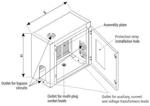
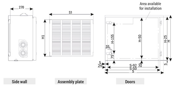
| Dimensions [mm] | ||||||
| H | 600 | 600 | 600 | 400 | 400 | 400 |
| S | 995 | 795 | 645 | 995 | 795 | 645 |
| H1 | 500 | 500 | 500 | 350 | 350 | 350 |
| S1 | 900 | 700 | 550 | 900 | 700 | 550 |
Figure 5a - Placement of the RELF switchgear
Notice:
In case of specific requirements that affect the switchgear cubicle dimensions, please contact the switchgear manufacturer.
Figure 5b - Placement of the RELF 36 kV switchgear
Notice:
In case of specific requirements that affect the switchgear cubicle dimensions, please contact the switchgear manufacturer.
Figure 5c - Placement of the RELF ex switchgear
Notice:
In case of specific requirements that affect the switchgear cubicle dimensions, please contact the switchgear manufacturer.
Figure 6a - Example dimensions of the cubicle bases and floor holes for RELF bays
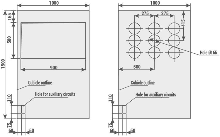
| Dimensions [mm] | |||
| S | 600 | 750 | 950 |
Note:
The presented solutions are examples. Solutions for specific projects available after contacting the manufacturer.
Figure 6b - Example dimensions of the cubicle bases and floor holes for RELF 36 kV bays
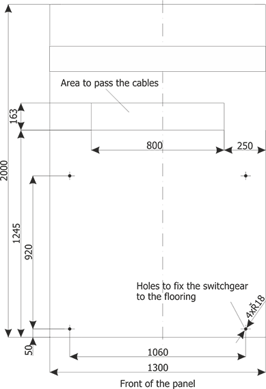
Note:
The presented solutions are examples. Solutions for specific projects available after contacting the manufacturer.
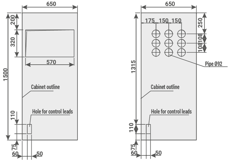
Figure 6c - Example dimensions of the cubicle bases and floor holes for RELF ex bays
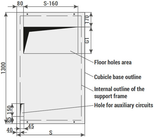
| Dimensions [mm] | |||
| H | 650 | 800 | 1000 |
| G1 | 310 mm - for 2 cable / phase 560 mm - for 4 cable / phase |
||
Note:
The presented solutions are examples. Solutions for specific projects available after contacting the manufacturer.
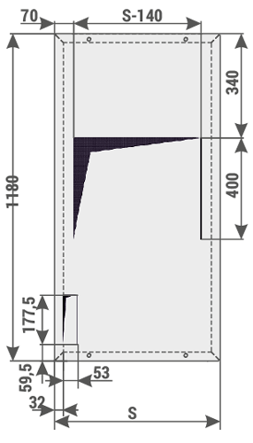
Figure 7a - RELF switchgear support frame
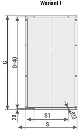
| Dimensions [mm] | |||
| G | 1180 | 1180 | 1180 |
| S | 600 | 750 | 950 |
| S1 | 350 | 500 | 700 |
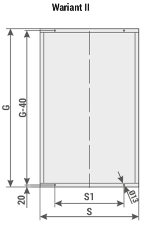
| Dimensions [mm] | ||||||||
| G | 1500 | 1550 | 1563 | 1600 | 1650 | |||
| S | 650 | 800 | 650 | 800 | 1000 | 800 | 1000 | 1000 |
| S1 | 400 | 500 | 400 | 500 | 700 | 500 | 700 | 700 |
Data sheet examples
RELF (product range with a cabinet depth of 1250 mm) - marking sheets
* The presented data sheets are only examples of solutions, which may change. In case of switchgears with technical parameters and bay configurations different than the ones presented, appropriate data sheets are available directly at the manufacturer or on the www.zpue.com website.| RELF | ||
| 1. | Sheet 1.1 | Incoming/outgoing feeder |
| 2. | Sheet 1.2 | Feeder with switch disconnector |
| 3. | Sheet 1.3 | Bus coupler bay with circuit breaker |
| 4. | Sheet 1.4 | Bus coupler bay with sectionalizer |
| 5. | Sheet 1.5 | Voltage metering bay |
Sheet 1.1 - RELF - Incoming/outgoing feeder
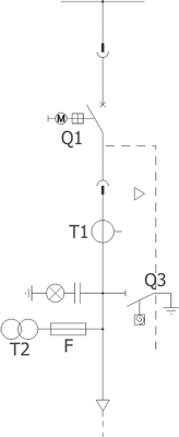
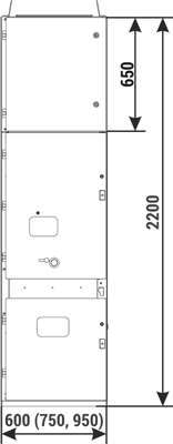
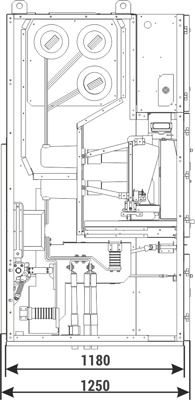
| Parameters: | ||
| Rated voltage | [kV] | 12/17,5 |
| Rated power-frequency withstand voltage | [kV] | 28/38 |
| Rated lightning impulse withstand voltage | [kV] | 75/95 |
| Rated frequency | [Hz] | 50 |
| Rated continuous current | [A] | 630-2500 |
| Main busbars rated cotinuous current | [A] | 630-2500 |
| Rated short-time withstand current | [kA/3s] | up to 31,5 |
| Rated peak withstand current | [kA] | up to 80 |
| Withstand for internal arcing fault | [kA/1s] | up to 31,5 |
| Protection degree | up to IP4X | |
| Equipment: | ||
| Circuit breaker/contactor | Q1 | VB-4 (ZPUE), SION (Siemens); VD4/HD4 (ABB); HVX (Schneider Electric); 3TM (Siemens); ConVac (ABB) |
| Current transformer | T1 | various manufacturers |
| Earthing switch | Q3 | US1 (ZPUE); EK6 (ABB) |
| Note: We allow the possibility of arranging the bay configuration concerning its function and equipment (type/manufacturer) |
||
Sheet 1.2 - RELF - Feeder with switch disconnector
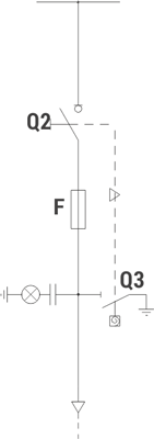
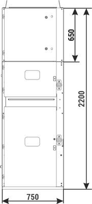
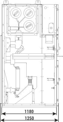
| Parameters: | ||
| Rated voltage | [kV] | 12/17,5 |
| Rated power-frequency withstand voltage | [kV] | 28/38 |
| Rated lightning impulse withstand voltage | [kV] | 75/95 |
| Rated frequency | [Hz] | 50 |
| Rated continuous current | [A] | 400-1250 |
| Main busbars rated cotinuous current | [A] | 630-2500 |
| Rated short-time withstand current | [kA/3s] | up to 31,5 |
| Rated peak withstand current | [kA] | up to 80 |
| Withstand for internal arcing fault | [kA/1s] | up to 31,5 |
| Protection degree | up to IP4X | |
| Equipment: | ||
| Circuit breaker | Q2 | NALF (ABB); OMB (ZWAE) |
| Earthing switch | Q3 | fast, with an impulse drive |
| Note: We allow the possibility of arranging the bay configuration concerning its function and equipment (type/manufacturer) |
||
Sheet 1.3 - RELF - Bus coupler bay with circuit breaker
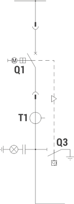
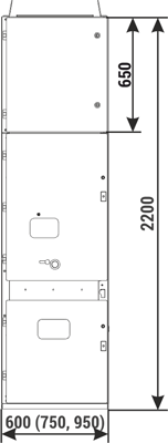
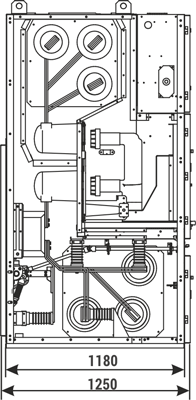
| Parameters: | ||
| Rated voltage | [kV] | 12/17,5 |
| Rated power-frequency withstand voltage | [kV] | 28/38 |
| Rated lightning impulse withstand voltage | [kV] | 75/95 |
| Rated frequency | [Hz] | 50 |
| Rated continuous current | [A] | 630-2500 |
| Main busbars rated cotinuous current | [A] | 630-2500 |
| Rated short-time withstand current | [kA/3s] | up to 31,5 |
| Rated peak withstand current | [kA] | up to 80 |
| Withstand for internal arcing fault | [kA/1s] | up to 31,5 |
| Protection degree | up to IP4X | |
| Equipment: | ||
| Circuit breaker | Q1 | VB-4 (ZPUE); SION (Siemens); VD4/HD4 (ABB); HVX (Schneider Electric) |
| Current transformer | T1 | various manufacturers |
| Earthing switch | Q3 | US1 (ZPUE); EK6 (ABB) |
| Note: We allow the possibility of arranging the bay configuration concerning its function and equipment (type/manufacturer) |
||
Sheet 1.4 - RELF - Bus coupler bay with sectionalizer
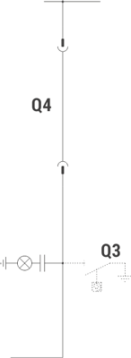
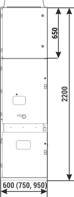
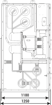
| Parameters: | ||
| Rated voltage | [kV] | 12/17,5 |
| Rated power-frequency withstand voltage | [kV] | 28/38 |
| Rated lightning impulse withstand voltage | [kV] | 75/95 |
| Rated frequency | [Hz] | 50 |
| Rated continuous current | [A] | 630-2500 |
| Main busbars rated cotinuous current | [A] | 630-2500 |
| Rated short-time withstand current | [kA/3s] | up to 31,5 |
| Rated peak withstand current | [kA] | up to 80 |
| Withstand for internal arcing fault | [kA/1s] | up to 31,5 |
| Protection degree | up to IP4X | |
| Equipment: | ||
| Sectionalizer | Q4 | made by ZPUE |
| Note: We allow the possibility of arranging the bay configuration concerning its function and equipment (type/manufacturer) |
||
Sheet 1.5 - RELF - Voltage metering bay
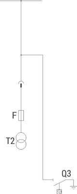
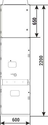
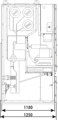
| Parameters: | ||
| Rated voltage | [kV] | 12/17,5 |
| Rated power-frequency withstand voltage | [kV] | 28/38 |
| Rated lightning impulse withstand voltage | [kV] | 75/95 |
| Rated frequency | [Hz] | 50 |
| Main busbars rated cotinuous current | [A] | 630-2500 |
| Rated short-time withstand current | [kA/3s] | up to 31,5 |
| Rated peak withstand current | [kA] | up to 80 |
| Withstand for internal arcing fault | [kA/1s] | up to 31,5 |
| Protection degree | up to IP4X | |
| Equipment: | ||
| Withdrawable module | Metering bay - withdrawable module with voltage transformers | |
| Voltage transformer | T2 | various manufacturers |
| Earthing switch | Q3 | US1 (ZPUE); EK6 (ABB) |
| Notice: We allow the possibility of arranging the bay configuration concerning its function and equipment (type/manufacturer) |
||
RELF - marking sheets
| RELF | ||
| 1. | Sheet 2.1 | Feeder with circuit breaker |
| 2. | Sheet 2.2 | Feeder with switch disconnector |
| 3. | Sheet 2.3 | Outgoing feeder with contactor |
| 4. | Sheet 2.4 | Bus coupler bay with circuit breaker |
| 5. | Sheet 2.5 | Bus coupler bay with sectionalizer |
| 6. | Sheet 2.6 | Metering bay - withdrawable module with voltage transformers |
| * The presented data sheets are only examples of solutions, which may change. In case of switchgears with technical parameters and bay configurations different than the ones presented, appropriate data sheets are available directly at the manufacturer or on the www.zpue.com website. | ||
Sheet 2.1 - RELF - Feeder with circuit breaker
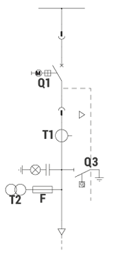
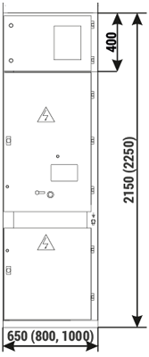
| Parameters: | ||
| Rated voltage | [kV] | 12/17,5/24 |
| Rated power-frequency withstand voltage | [kV] | 28/38/50 |
| Rated lightning impulse withstand voltage | [kV] | 75/95/125 |
| Rated frequency | [Hz] | 50 |
| Rated continuous current | [A] | 630-4000 |
| Main busbars rated cotinuous current | [A] | 630-4000 |
| Rated short-time withstand current | [kA/3s] | up to 40 |
| Rated peak withstand current | [kA] | up to 100 |
| Withstand for internal arcing fault | [kA/1s] | up to 31,5 and up to 40/0,5s |
| Protection degree | up to IP4X | |
| Equipment: | ||
| Circuit breaker | Q1 | VB-4 (ZPUE); SION (Siemens); VD4/HD4 (ABB); HVX (Schneider Electric) |
| Current transformer | T1 | various manufacturers |
| Earthing switch | Q3 | US1 (ZPUE); EK6 (ABB) |
| Note: We allow the possibility of arranging the bay configuration concerning its function and equipment (type/manufacturer) |
||
Sheet 2.2 - RELF - Feeder with switch disconnector

| Parameters: | ||
| Rated voltage | [kV] | 12/17,5/24 |
| Rated power-frequency withstand voltage | [kV] | 28/38/50 |
| Rated lightning impulse withstand voltage | [kV] | 75/95/125 |
| Rated frequency | [Hz] | 50 |
| Rated continuous current | [A] | 400-1250 |
| Main busbars rated cotinuous current | [A] | 630-4000 |
| Rated short-time withstand current | [kA/3s] | up to 31,5 |
| Rated peak withstand current | [kA] | up to 80 |
| Withstand for internal arcing fault | [kA/1s] | up to 31,5 |
| Protection degree | up to IP4X | |
| Equipment: | ||
| Circuit breaker | Q2 | NALF (ABB); OMB (ZWAE) |
| Earthing switch | Q3 | fast, with an impulse drive |
| Note: We allow the possibility of arranging the bay configuration concerning its function and equipment (type/manufacturer) |
||
Sheet 2.3 - RELF - Outgoing feeder with contactor
| Parameters: | ||
| Rated voltage | [kV] | 12 |
| Rated power-frequency withstand voltage | [kV] | 28 |
| Rated lightning impulse withstand voltage | [kV] | 75 |
| Rated frequency | [Hz] | 50 |
| Rated continuous current | [A] | 400-630 |
| Main busbars rated cotinuous current | [A] | 630-4000 |
| Rated short-time withstand current | [kA/3s] | up to 31,5 |
| Rated peak withstand current | [kA] | up to 80 |
| Withstand for internal arcing fault | [kA/1s] | up to 31,5 |
| Protection degree | up to IP4X | |
| Equipment: | ||
| Contactor | Q2 | 3TM (Siemens); ConVac (ABB) |
| Current transformer | T1 | various manufacturers |
| Earthing switch | Q3 | US1 (ZPUE); EK6 (ABB) |
| Note: We allow the possibility of arranging the bay configuration concerning its function and equipment (type/manufacturer) |
||
Sheet 2.4 - RELF - Bus coupler bay with circuit breaker

| Parameters: | ||
| Rated voltage | [kV] | 12/17,5/24 |
| Rated power-frequency withstand voltage | [kV] | 28/38/50 |
| Rated lightning impulse withstand voltage | [kV] | 75/95/125 |
| Rated frequency | [Hz] | 50 |
| Rated continuous current | [A] | 630-4000 |
| Main busbars rated cotinuous current | [A] | 630-4000 |
| Rated short-time withstand current | [kA/3s] | up to 40 |
| Rated peak withstand current | [kA] | up to 100 |
| Withstand for internal arcing fault | [kA/1s] | up to 31,5 and up to 40/0,5s |
| Protection degree | up to IP4X | |
| Equipment: | ||
| Circuit breaker | Q1 | VB-4 (ZPUE); SION (Siemens); VD4/HD4 (ABB); HVX (Schneider Electric) |
| Current transformer | T1 | various manufacturers |
| Earthing switch | Q3 | US1 (ZPUE); EK6 (ABB) |
| Note: We allow the possibility of arranging the bay configuration concerning its function and equipment (type/manufacturer) |
||
Sheet 2.5 - RELF - Bus coupler bay with sectionalizer

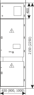
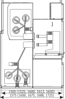
| Parameters: | ||
| Rated voltage | [kV] | 12/17,5/24 |
| Rated power-frequency withstand voltage | [kV] | 28/38/50 |
| Rated lightning impulse withstand voltage | [kV] | 75/95/125 |
| Rated frequency | [Hz] | 50 |
| Rated continuous current | [A] | 630-4000 |
| Main busbars rated cotinuous current | [A] | 630-4000 |
| Rated short-time withstand current | [kA/3s] | up to 40 |
| Rated peak withstand current | [kA] | up to 100 |
| Withstand for internal arcing fault | [kA/1s] | up to 31,5 and up to 40/0,5s |
| Protection degree | up to IP4X | |
| Equipment: | ||
| Short-circuiting device | Q4 | made by ZPUE |
| Note: We allow the possibility of arranging the bay configuration concerning its function and equipment (type/manufacturer) |
||
Sheet 2.6 - RELF - Metering bay - withdrawable module with voltage transformers
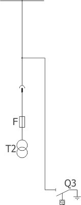
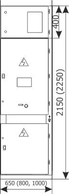
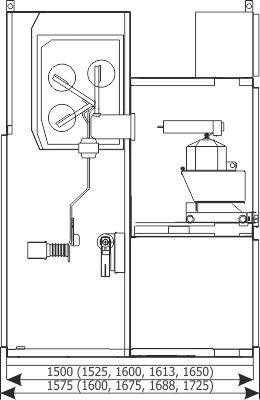
| Parameters: | ||
| Rated voltage | [kV] | 12/17,5/24 |
| Rated power-frequency withstand voltage | [kV] | 28/38/50 |
| Rated lightning impulse withstand voltage | [kV] | 75/95/125 |
| Rated frequency | [Hz] | 50 |
| Main busbars rated cotinuous current | [A] | 630-4000 |
| Rated short-time withstand current | [kA/3s] | up to 40 |
| Rated peak withstand current | [kA] | up to 100 |
| Withstand for internal arcing fault | [kA/1s] | up to 31,5 and up to 40/0,5s |
| Protection degree | up to IP4X | |
| Equipment: | ||
| Withdrawable module | Metering bay - withdrawable module with voltage transformers | |
| Voltage transformer | T2 | various manufacturers |
| Earthing switch | Q3 | US1 (ZPUE); EK6 (ABB) |
| Note: We allow the possibility of arranging the bay configuration concerning its function and equipment (type/manufacturer) |
||
RELF 36 kV - marking sheets
| RELF 36 kV | ||
| 1. | Sheet 3.1 | Feeder with circuit breaker |
| 2. | Sheet 3.2 | Bus coupler bay with circuit breaker |
| 3. | Sheet 3.3 | Bus coupler bay with short-circuiting device |
| 4 | Sheet 3.4 | Metering bay - withdrawable module with voltage transformers |
| * The presented data sheets are only examples of solutions, which may change. In case of switchgears with technical parameters and bay configurations different than the ones presented, appropriate data sheets are available directly at the manufacturer or on the www.zpue.com website. | ||
Sheet 3.1 - RELF 36 - Feeder with circuit breaker
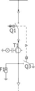
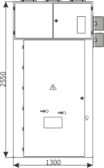
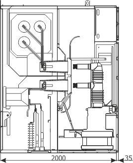
| Parameters: | ||
| Rated voltage | [kV] | 36/40,5* |
| Rated power-frequency withstand voltage | [kV] | 95/85,5(5min)/95(1min)* |
| Rated lightning impulse withstand voltage | [kV] | 190 |
| Rated frequency | [Hz] | 50 |
| Rated continuous current | [A] | up to 1600 |
| Main busbars rated cotinuous current | [A] | up to 1600 |
| Rated short-time withstand current | [kA] | up to 25(3s) and up to 31,5(1s) |
| Rated peak withstand current | [kA] | 63/80 |
| Withstand for internal arcing fault | [kA/1s] | up to 25 |
| Protection degree | up to IP4X | |
| Equipment: | ||
| Circuit breaker | Q1 | VD4 (ABB) |
| Current transformer | T1 | different manufacturers |
| Earthing switch | Q3 | EK6 (ABB) |
| Overvoltage limiter | F1 | GXE51 (ABB) |
| * - in accordance with GOST standards Note: We allow the possibility of arranging the bay configuration concerning its function and equipment (type/manufacturer) |
||
Sheet 3.2 - RELF 36 - Bus coupler bay with circuit breaker

| Parameters: | ||
| Rated voltage | [kV] | 36/40,5* |
| Rated power-frequency withstand voltage | [kV] | 95/85,5(5min)/95(1min)* |
| Rated lightning impulse withstand voltage | [kV] | 190 |
| Rated frequency | [Hz] | 50 |
| Rated continuous current | [A] | up to 1600 |
| Main busbars rated cotinuous current | [A] | up to 1600 |
| Rated short-time withstand current | [kA] | up to 25(3s) and up to 31,5(1s) |
| Rated peak withstand current | [kA] | 63/80 |
| Withstand for internal arcing fault | [kA/1s] | up to 25 |
| Protection degree | up to IP4X | |
| Equipment: | ||
| Circuit breaker | Q1 | VD4 (ABB) |
| Current transformer | T1 | different manufacturers |
| * - in accordance with GOST standards Note: We allow the possibility of arranging the bay configuration concerning its function and equipment (type/manufacturer) |
||
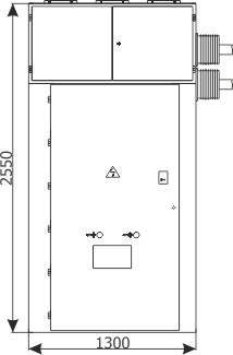
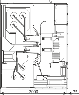
Sheet 3.3 - RELF 36 - Bus coupler bay with sectionalizer
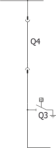
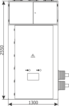
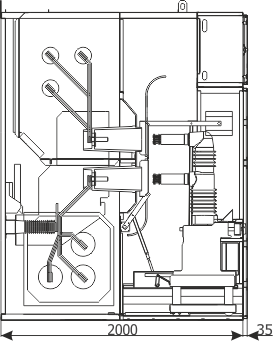
| Parameters: | ||
| Rated voltage | [kV] | 36/40,5* |
| Rated power-frequency withstand voltage | [kV] | 95/85,5(5min)/95(1min)* |
| Rated lightning impulse withstand voltage | [kV] | 190 |
| Rated frequency | [Hz] | 50 |
| Rated continuous current | [A] | up to 1600 |
| Main busbars rated cotinuous current | [A] | up to 1600 |
| Rated short-time withstand current | [kA] | up to 25(3s) and up to 31,5(1s) |
| Rated peak withstand current | [kA] | 63/80 |
| Withstand for internal arcing fault | [kA/1s] | up to 25 |
| Protection degree | up to IP4X | |
| Equipment: | ||
| Sectionalizer | Q4 | made by ABB |
| Earthing switch | Q3 | EK6 (ABB) |
| * - in accordance with GOST standards Note: We allow the possibility of arranging the bay configuration concerning its function and equipment (type/manufacturer) |
||
Sheet 3.4 - RELF 36 - Metering bay - withdrawable module with voltage transformers
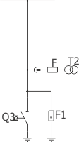
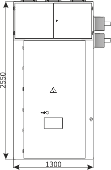

| Parameters: | ||
| Rated voltage | [kV] | 36/40,5* |
| Rated power-frequency withstand voltage | [kV] | 95/85,5(5min)/95(1min)* |
| Rated lightning impulse withstand voltage | [kV] | 190 |
| Rated frequency | [Hz] | 50 |
| Main busbars rated cotinuous current | [A] | up to 1600 |
| Rated short-time withstand current | [kA/3s] | up to 25(3s) and up to 31,5(1s) |
| Rated peak withstand current | [kA] | 63/80 |
| Withstand for internal arcing fault | [kA/1s] | up to 25 |
| Protection degree | up to IP4X | |
| Equipment: | ||
| Withdrawable module | Metering bay - withdrawable module with voltage transformers | |
| Voltage transformer | T2 | different manufacturers |
| Earthing switch | Q3 | EK6 (ABB) |
| Overvoltage limiter | F1 | GXE51 (ABB) |
| * - in accordance with GOST standards Note: We allow the possibility of arranging the bay configuration concerning its function and equipment (type/manufacturer) |
||
RELF ex - marking sheets
| RELF ex | ||
| 1. | Sheet 4.1 | Feeder with circuit breaker |
| 2. | Sheet 4.2 | Feeder with switch disconnector |
| 3. | Sheet 4.3 | Bus coupler bay with circuit breaker |
| 4 | Sheet 4.4 | Bus coupler bay with sectionalizer |
| 4 | Sheet 4.5 | Metering bay - withdrawable module with voltage transformers |
| * The presented data sheets are only examples of solutions, which may change. In case of switchgears with technical parameters and bay configurations different than the ones presented, appropriate data sheets are available directly at the manufacturer or on the www.zpue.com website. | ||
Sheet 4.1 - RELF ex - Feeder with circuit breaker
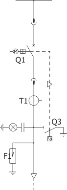
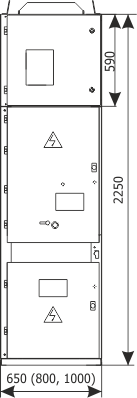
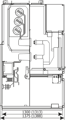
| Parameters: | ||
| Rated voltage | [kV] | 12; 17,5 |
| Rated power-frequency withstand voltage | [kV] | 28/38 |
| Rated lightning impulse withstand voltage | [kV] | 75/95 |
| Rated frequency | [Hz] | 50 |
| Rated continuous current | [A] | 630-2500 |
| Main busbars rated cotinuous current | [A] | 630-2500 |
| Rated short-time withstand current | [kA/3s] | up to 25 |
| Rated peak withstand current | [kA] | up to 63 |
| Withstand for internal arcing fault | [kA/1s] | up to 25 |
| Protection degree | up to IP4X | |
| Equipment: | ||
| Circuit breaker | Q1 | VB-4 (ZPUE); VD4 (ABB); SION (Siemens); HVX (Schneider Electric) |
| Current transformer | T1 | various manufacturers |
| Earthing switch | Q3 | US1 (ZPUE); EK6 (ABB) |
| Note: We allow the possibility of arranging the bay configuration concerning its function and equipment (type/manufacturer) |
||
Sheet 4.2 - RELF ex - Feeder with switch disconnector

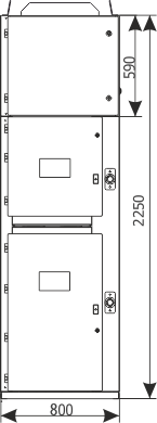
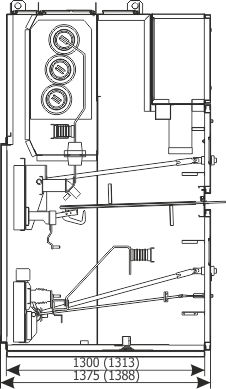
| Parameters: | ||
| Rated voltage | [kV] | 12; 17,5 |
| Rated power-frequency withstand voltage | [kV] | 28/38 |
| Rated lightning impulse withstand voltage | [kV] | 75/95 |
| Rated frequency | [Hz] | 50 |
| Rated continuous current | [A] | 400-1250 |
| Main busbars rated cotinuous current | [A] | 630-2500 |
| Rated short-time withstand current | [kA/3s] | up to 25 |
| Rated peak withstand current | [kA] | up to 63 |
| Withstand for internal arcing fault | [kA/1s] | up to 25 |
| Protection degree | up to IP4X | |
| Equipment: | ||
| Circuit breaker | Q2 | NALF (ABB); OMB (ZWAE) |
| Earthing switch | Q3 | fast, with an impulse drive |
| Note: We allow the possibility of arranging the bay configuration concerning its function and equipment (type/manufacturer) |
||
Sheet 4.3 - RELF ex - Bus coupler bay with circuit breaker

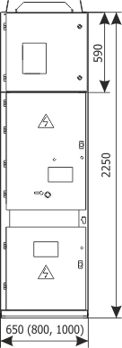
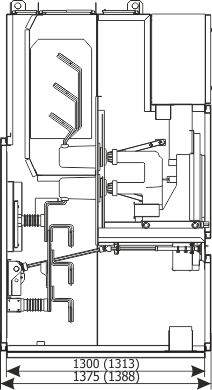
| Parameters: | ||
| Rated voltage | [kV] | 12; 17,5 |
| Rated power-frequency withstand voltage | [kV] | 28/38 |
| Rated lightning impulse withstand voltage | [kV] | 75/95 |
| Rated frequency | [Hz] | 50 |
| Rated continuous current | [A] | 630-2500 |
| Main busbars rated cotinuous current | [A] | 630-2500 |
| Rated short-time withstand current | [kA/3s] | up to 25 |
| Rated peak withstand current | [kA] | up to 63 |
| Withstand for internal arcing fault | [kA/1s] | up to 25 |
| Protection degree | up to IP4X | |
| Equipment: | ||
| Circuit breaker | Q1 | VB-4 (ZPUE); VD4 (ABB); SION (Siemens); HVX (Schneider Electric) |
| Current transformer | T1 | various manufacturers |
| Earthing switch | Q3 | US1 (ZPUE); EK6 (ABB) |
| Note: We allow the possibility of arranging the bay configuration concerning its function and equipment (type/manufacturer) |
||
Sheet 4.4 - RELF ex - Bus coupler bay with sectionalizer

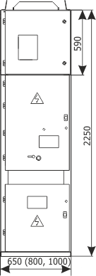
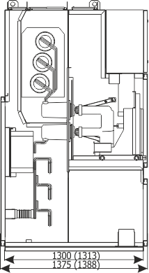
| Parameters: | ||
| Rated voltage | [kV] | 12; 17,5 |
| Rated power-frequency withstand voltage | [kV] | 28/38 |
| Rated lightning impulse withstand voltage | [kV] | 75/95 |
| Rated frequency | [Hz] | 50 |
| Rated continuous current | [A] | 630-2500 |
| Main busbars rated cotinuous current | [A] | 630-2500 |
| Rated short-time withstand current | [kA/3s] | up to 25 |
| Rated peak withstand current | [kA] | up to 63 |
| Withstand for internal arcing fault | [kA/1s] | up to 25 |
| Protection degree | up to IP4X | |
| Equipment: | ||
| Sectionalizer | Q4 | Made by ZPUE |
| Current transformer | T1 | various manufacturers |
| Note: We allow the possibility of arranging the bay configuration concerning its function and equipment (type/manufacturer) |
||
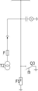
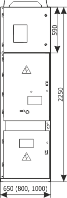
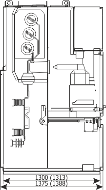
Sheet 4.5 - RELF ex - Metering bay - withdrawable module with voltage transformers
| Parameters: | ||
| Rated voltage | [kV] | 12; 17,5 |
| Rated power-frequency withstand voltage | [kV] | 28/38 |
| Rated lightning impulse withstand voltage | [kV] | 75/95 |
| Rated frequency | [Hz] | 50 |
| Main busbars rated cotinuous current | [A] | up to 2400 |
| Rated short-time withstand current | [kA/3s] | up to 25 |
| Rated peak withstand current | [kA] | up to 63 |
| Withstand for internal arcing fault | [kA/1s] | up to 25 |
| Protection degree | up to IP4X | |
| Equipment: | ||
| Withdrawable module | Metering bay - withdrawable module with voltage transformers | |
| Voltage transformer | T2 | various manufacturers |
| Earthing switch | Q3 | US1 (ZPUE); EK6 (ABB) |
| Surge arresters | F1 | Polim (ABB) or other |
| Note: We allow the possibility of arranging the bay configuration concerning its function and equipment (type/manufacturer) |
||

