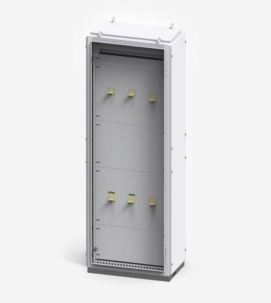
The INSTAL-BLOK indoor cabinet system manufactured by ZPUE S.A. is a state of the art, modular solution based on a framework design with maintenance-free bolt fasteners, which enable simple and flexible installation of low voltage controlgear, switchgear and protection devices and other accessories in order to meet power engineering, industrial automation and other industry needs.
Switchgear design
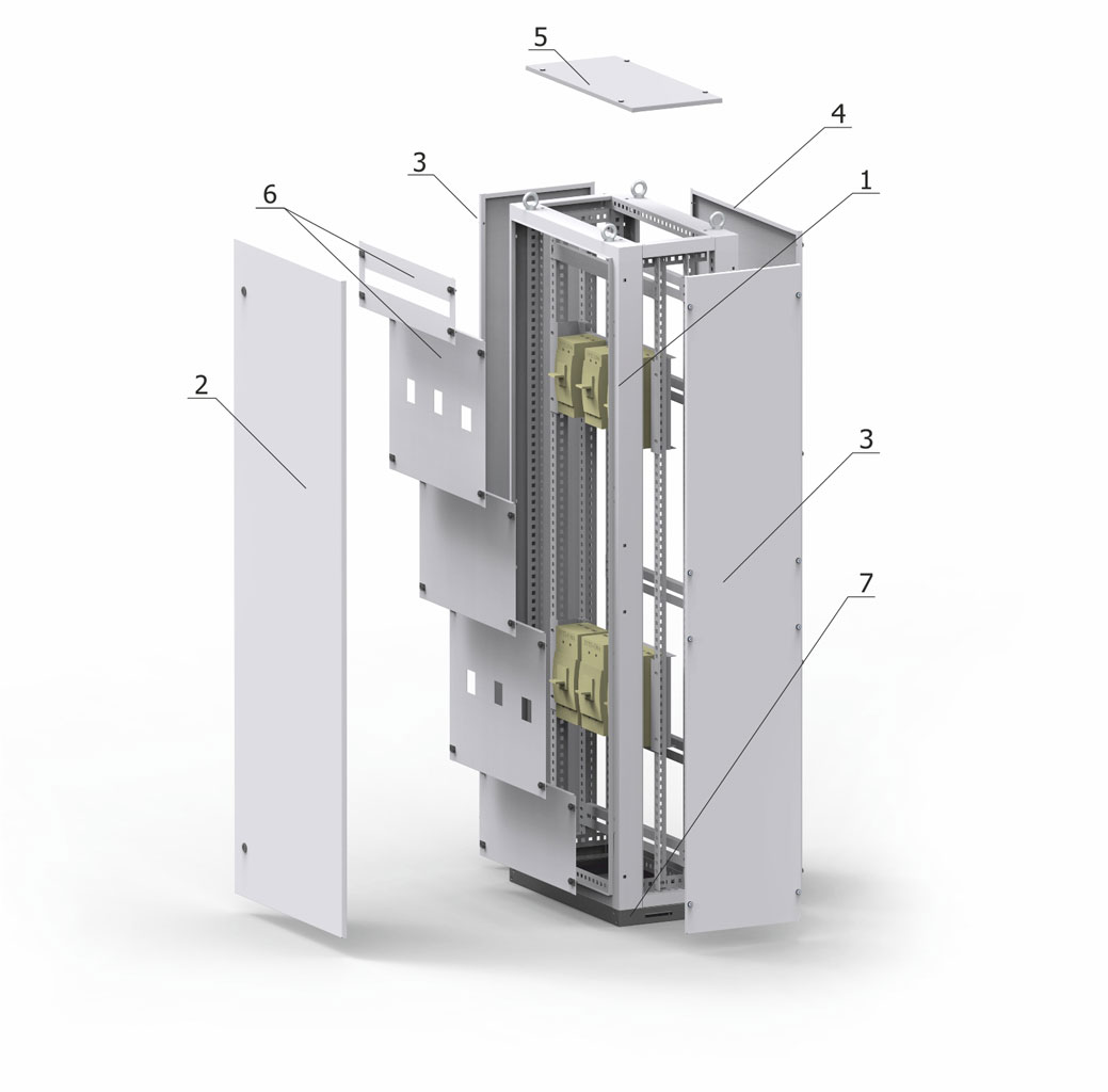
- framework
- doors
- side wall
- back wall
- roof
- front panels
- pedestal
| Width [mm]: | |
| Value | Designation |
| 400 | 04 |
| 500 | 05 |
| 600 | 06 |
| 700 | 07 |
| 800 | 08 |
| 900 | 09 |
| 1000 | 10 |
| 1100 | 11 |
| 1200 | 12 |
Cabinet type is marked with a code for cabinet dimensions:
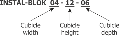
| Height [mm]: | |
| Value | Designation |
| 1000 | 10 |
| 1200 | 12 |
| 1400 | 14 |
| 1600 | 16 |
| 1800 | 18 |
| 2000 | 20 |
| Depth [mm]: | |
| Value | Designation |
| 400 | 04 |
| 600 | 06 |
| 800 | 08 |
| 1000 | 10 |
Note:
At the customer's request it is possible manufacture a cabinet with other dimensions.
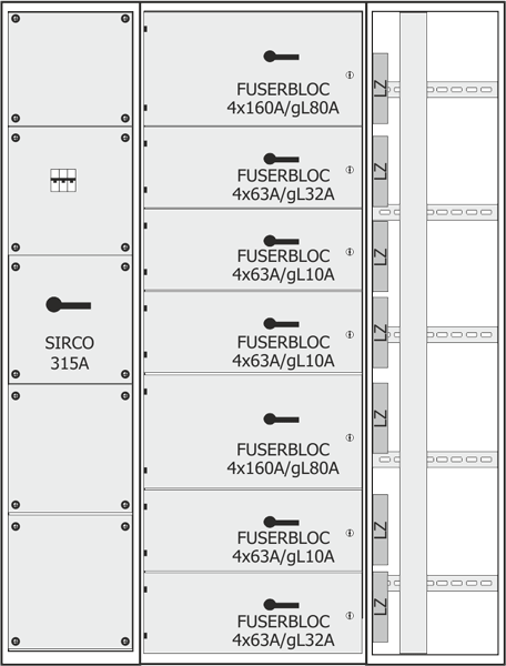
Devices that may be installed in the Instal-Blok switchgear bays
Due to the very wide range of possible applications of the INSTAL-BLOK switchgear, the catalogue presents only the most frequently used solution.
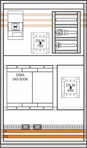
Bays with coupler or power circuit breaker, from 630 to 1600 A
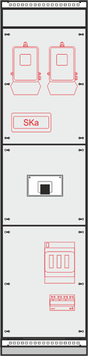
| Area of application | Incoming bay Outgoing bay Bus coupler bay |
| Ingress protection rating | IP20 without doors Up to IP66 with doors |
| Bay dimensions | Height: from 1800 to 2000 mm Width: from 500 to 1000 mm Depth: from 400 to 800 mm (depending on the device type) |
| Possibility of installing devices |
- stationary or withdrawable power circuit breaker from 630 to 1600 A - stationary or withdrawable compact circuit breaker, with manual or motor drive from 630 to 1600 A - box fuse switch disconnector from 630 to 1600 A - snap action disconnector from 630 to 1600 A |
| Additional devices | - place for installation of metering panel - drive control automation - surge arrester etc. |
| Connection | From the top: bus duct / busbar / cable From the bottom: bus duct / busbar / cable |
| Other | The possibility of installation of small modular devices |
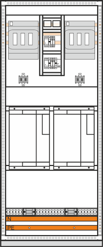
Incoming/outgoing bays
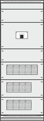
| Area of application | Power- supply receiving bay |
| Ingress protection rating | Ip20 without doors Up to IP66 with doors |
| Bay dimensions | Height: from 1800 to 2000 mm Width: from 500 to 1000 mm Depth: from 400 to 800 mm (depending on the device type) |
| Possibility of installing devices |
Incoming feeders: - stationary or withdrawable compact circuit breaker, with manual or motor drive from 630 to 1600 A - box fuse switch disconnector from 630 to 1600 A - snap action disconnector from 630 to 1600 A Outgoing feeders: - fuse switch disconnectors up to 630 A - compact circuit breakers up to 630 A - modular devices |
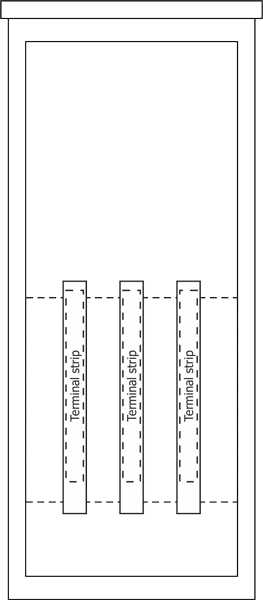
| Additional devices | The possibility of installing of terminal strips in various configurations |
| Connection | From the top: busbar / cable From the bottom: busbar / cable |
Cable duct bays
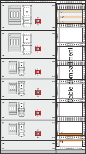
| Area of application | Outgoing bay with cable duct |
| Ingress protection rating | Ip20 without doors Up to IP66 with doors |
| Bay dimensions | Height: from 1800 to 2000 mm Width: from 800 to 1200 mm Depth: from 400 to 800 mm (depending on the device type) |
| Possibility of installing devices |
- compact circuit breakers up to 630 A - box fuse switch disconnectors up to 630 A - modular devices - motor blocks (protection, contactor, relay) up to 250 A - reversing motor blocks - star delta motor blocks - frequency converters |
| Additional devices | Instrumentation & Control devices |
| Connection | From the top: cable From the bottom: cable |
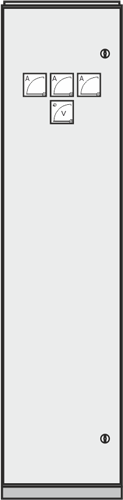
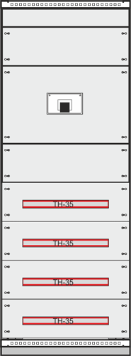
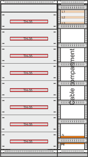
Swing frame bays
| Area of application | Bays for the installation of meters or control instrumentation |
| Ingress protection rating | Ip20 without doors Up to IP66 with doors |
| Bay dimensions | Height: from 1800 do 2000 mm Width: from 600 do 1000 mm Depth: from 400 do 800 mm (depending on the device type) |
| Possibility of installing devices |
Devices installed on a mounting plate: - fuse switch disconnectors up to 160 A - compact circuit breakers up to 160 A - metering and ordinary terminal strips - programmable controllers Devices installed on a swing frame: - full-size and TH35 rail mounted electricity meters - network analysers - ammeters - voltmeters - other instrumentation and control equipment |
| Additional devices | The possibility of installing terminal strips in various configurations |
| Connection | From the top: cable From the bottom: cable |
| Others | A cable duct can be attached to the bay |
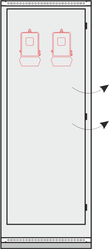
Free installation bays
| Area of application | Bays for the installation of large-sized equipment structures |
| Ingress protection rating | IP20 without doors Up to IP66 with doors |
| Bay dimensions | Height: from 1800 to 2000 mm Width: from 400 to 1000 mm Depth: from 400 to 800 mm (depending on the device type) |
| Possibility of installing devices |
- frequency converters - soft-starts - high-mass transformers - direct current batteries - 19” (rack) devices, after installation of guide bars |
| Connection | From the top: cable From the bottom: cable |
| Others |
A cable duct can be attached to the bay |
Capacitor bank bays
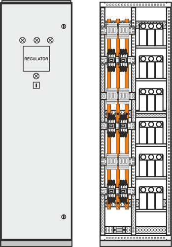
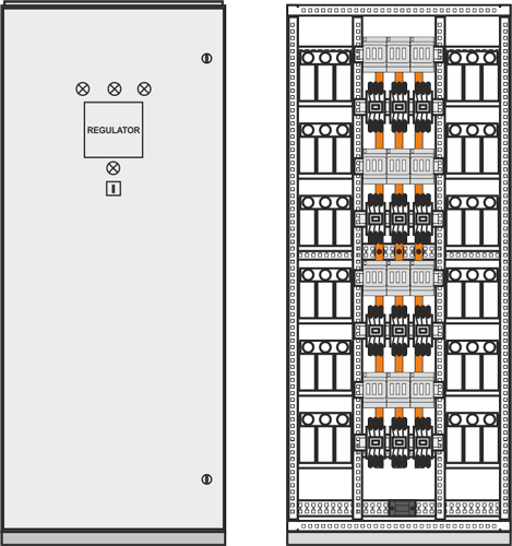
| Area of application | A bank for compensation of capacitive reactive power: - capacitor - capacitor and reactor |
| Ingress protection rating | From IP20 to IP54 |
| Bay dimensions | Height: 2000 mm Width: from 500 to 800 mm Depth: from 400 to 600 mm |
| Possibility of installing devices |
- 3 to 6 capacitor stages with a power of 60 to 200 kvar or capacitor and reactor stages from 60 to 100 kvar - 4 to 12 capacitor stages with a power of 120 to 260 kvar or up to 8 capacitor and reactor stages with a power up to 160 kvar |
| Connection | From the top: cable From the bottom: cable |
| Others | Bays with reactors are equipped with fans depending on the power of installed reactors |
Note:
- provided dimensions apply only to a protection rating up to IP31
- higher protection ratings require larger enclosure sizes
- more information on capacitor banks can be found in chapter BK, BKD — Capacitor banks
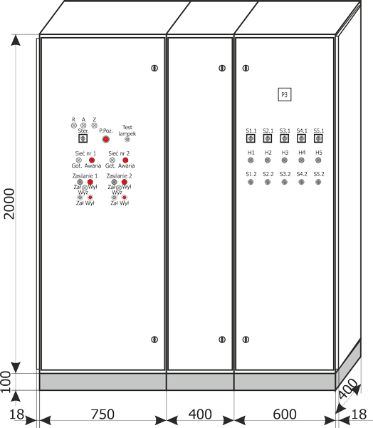
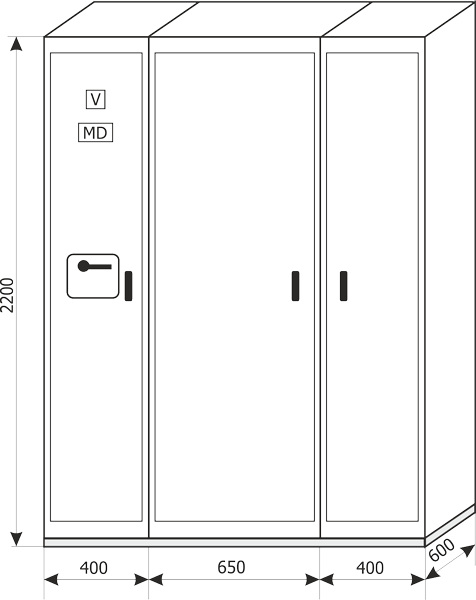
Placement of the switchgear and installation of connections
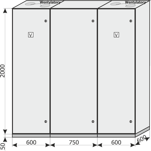
The INSTAL-BLOK switchgears are designed for indoors installation. They can be placed directly on concrete flooring of the facility. Regardless of the type of foundation, switchgears must be placed exactly horizontally (maximum deviation may not exceed 2 mm over 1 m of base length). The switchgear (single cell) should be fixed to the foundation with 4 M8 bolts in locations shown on Fig. 1. When placing the switchgear appropriate spacing should be maintained between the switchgear and other elements in the room in accordance with the regulations in force.
External connections are made as:
- cables from the bottom to the supply bay and outgoing bays from a cable duct,
- busbars or cables from the top to the supply bay,
- cable from the top to outgoing bays.
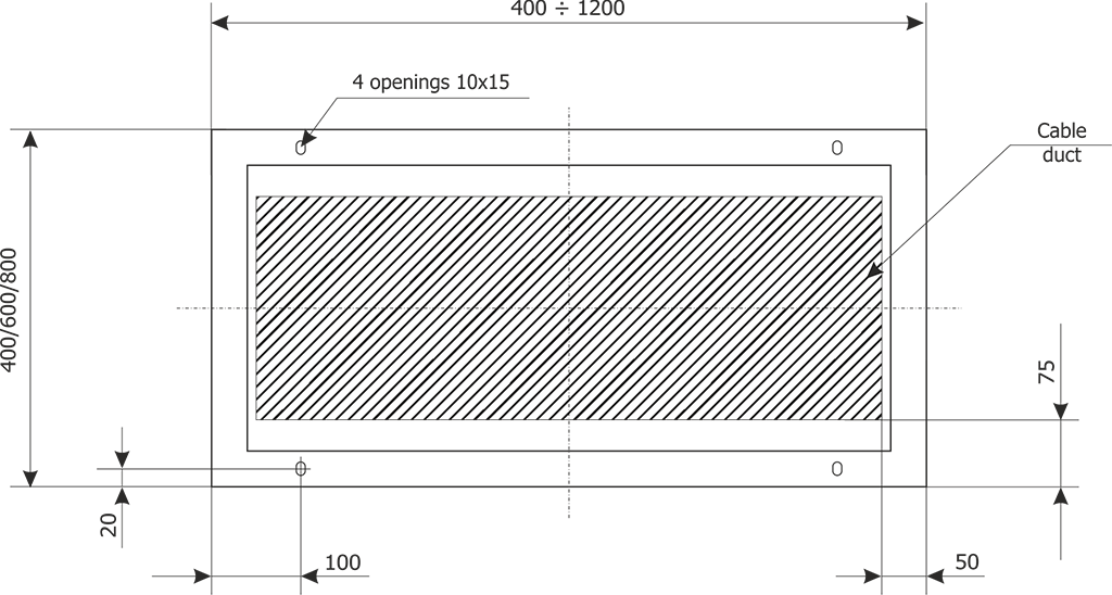
Note:
Duct depth should be adapted to the number and cross-section of the cables.
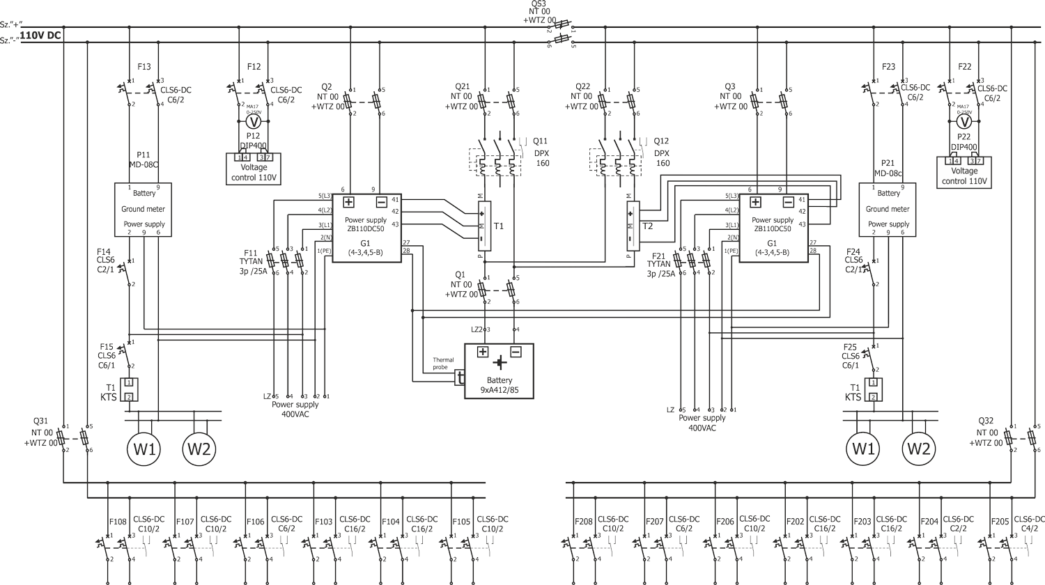
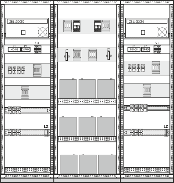
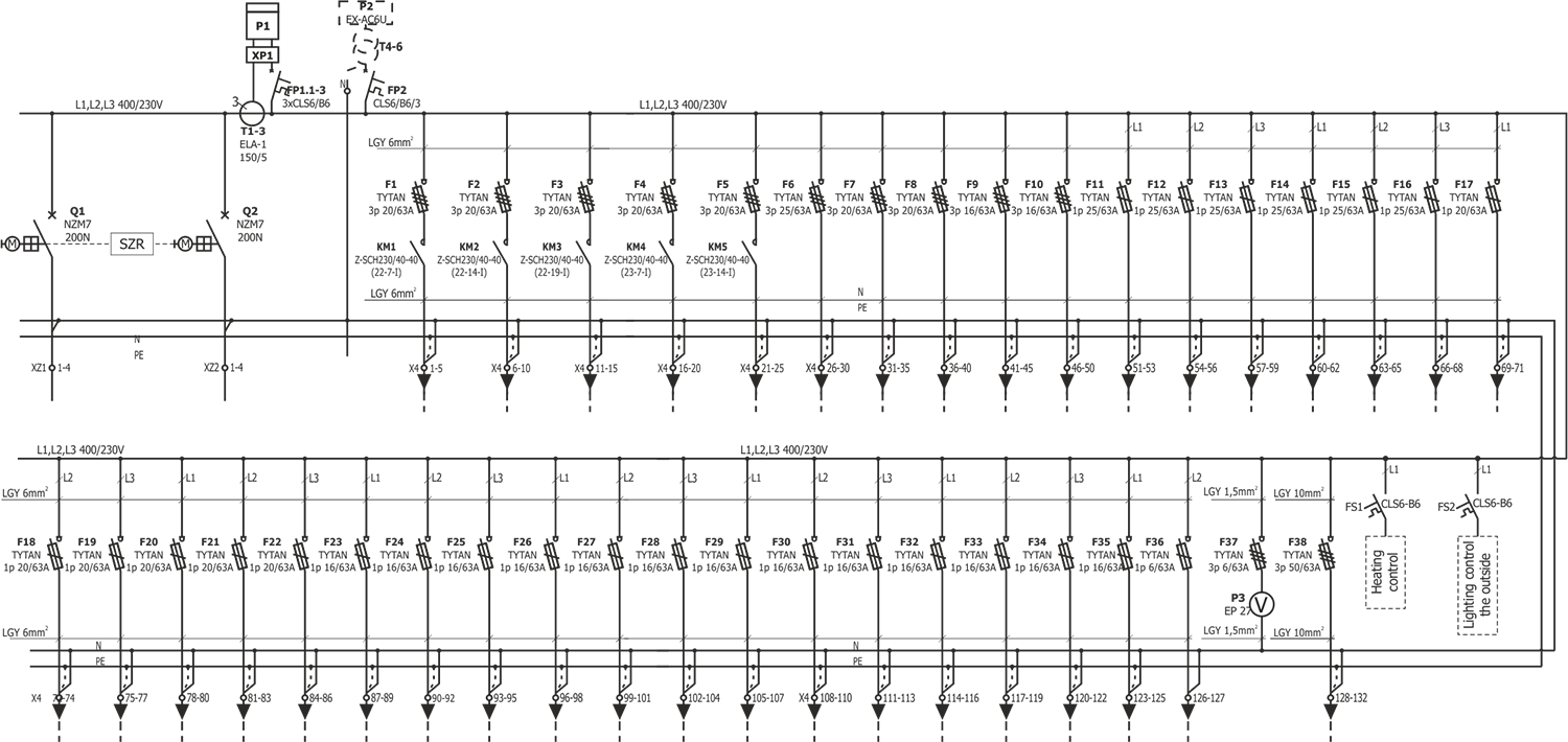
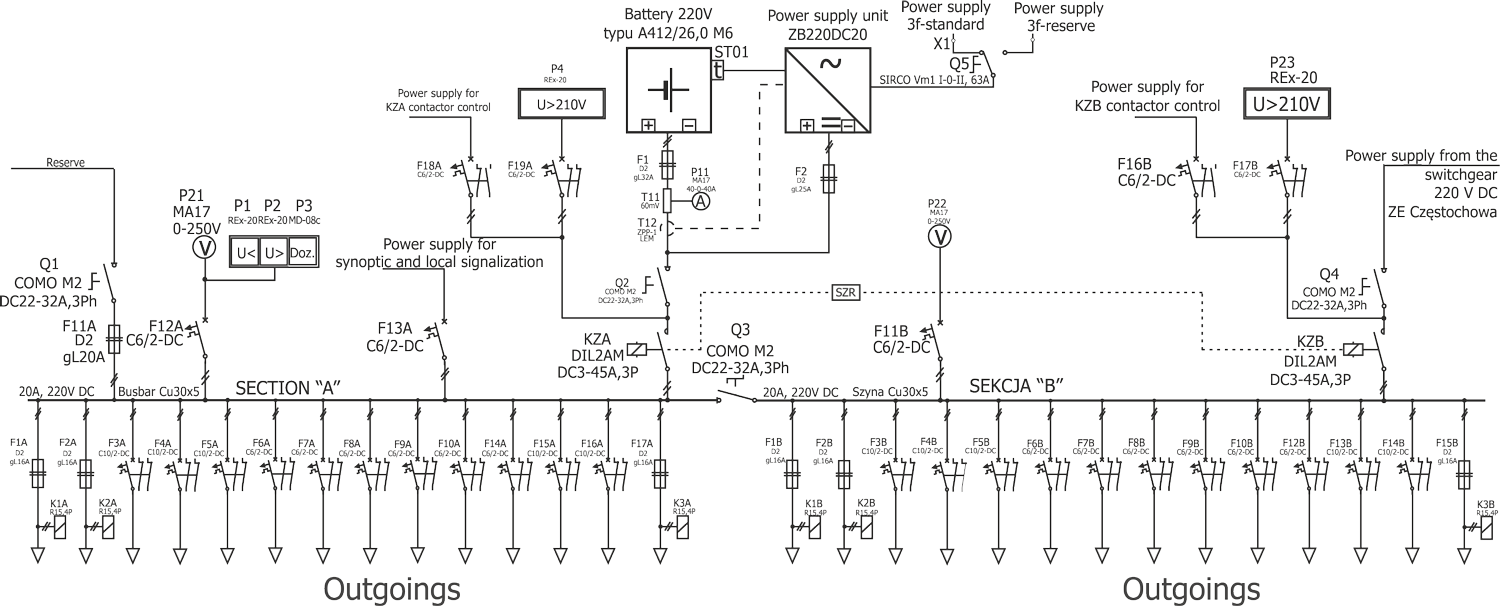
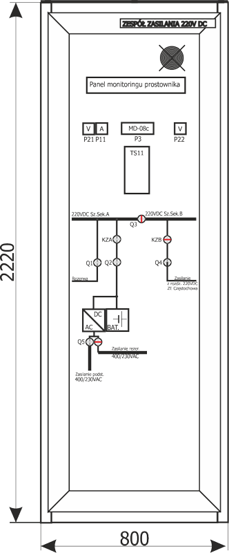
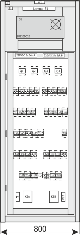
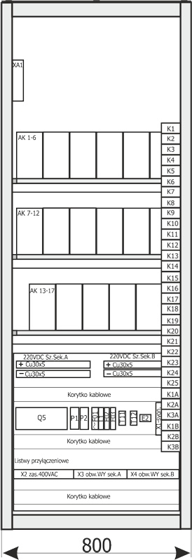
Custom designs — switchgears for main power supply stations
LV switchgear 220 V DC
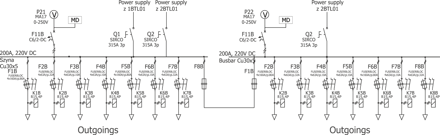
LV switchgear 220 V DC
LV switchgear 110 V DC