RN-W
ZR-W
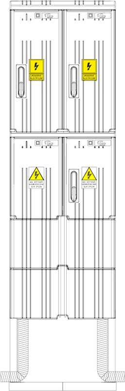
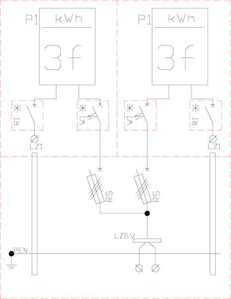
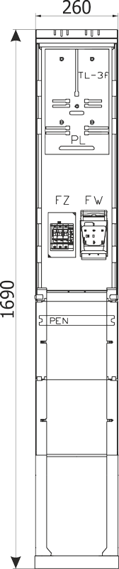
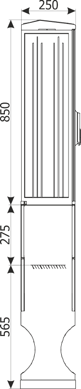
INSTAL-BLOK
BK, BKD

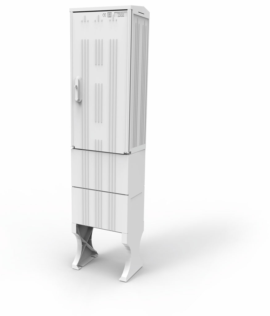
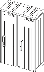
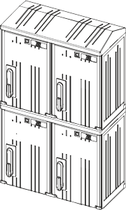
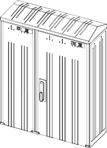
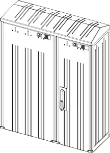
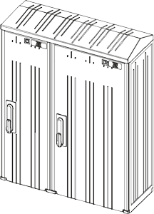
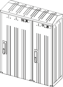
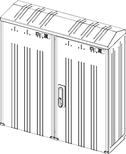
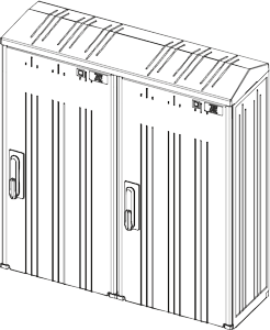
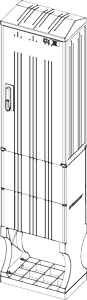
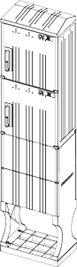
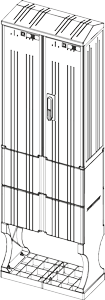
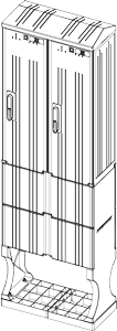
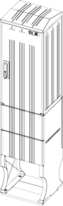
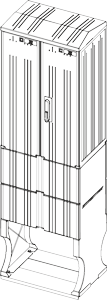
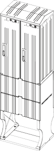
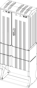
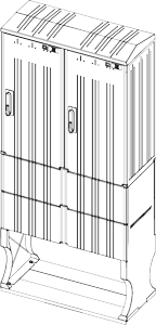
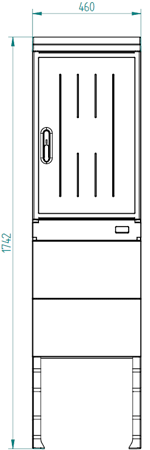
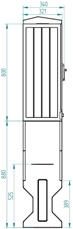
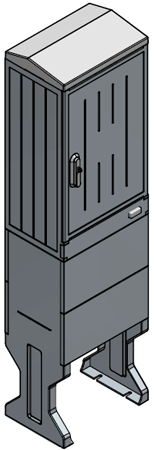
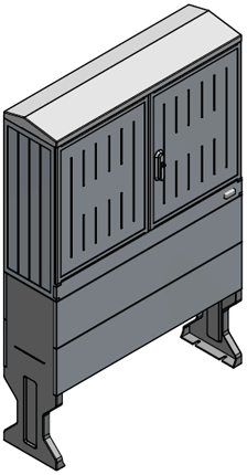
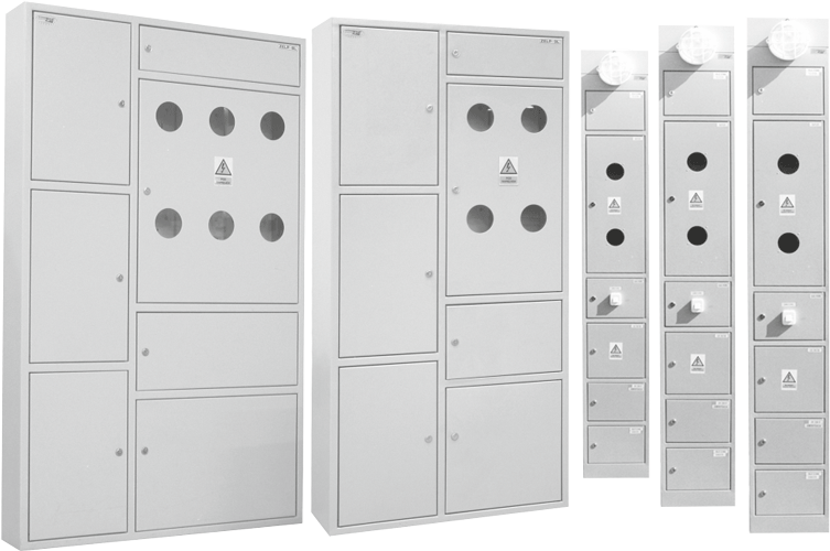
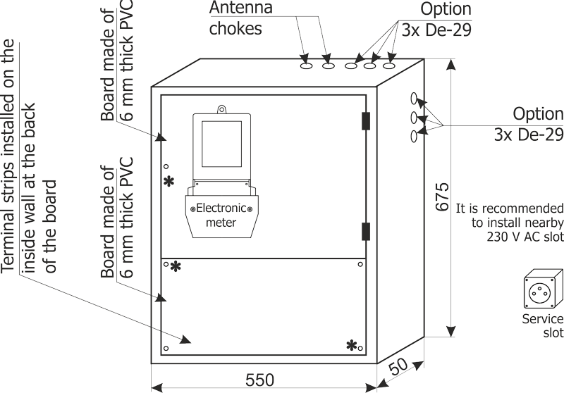
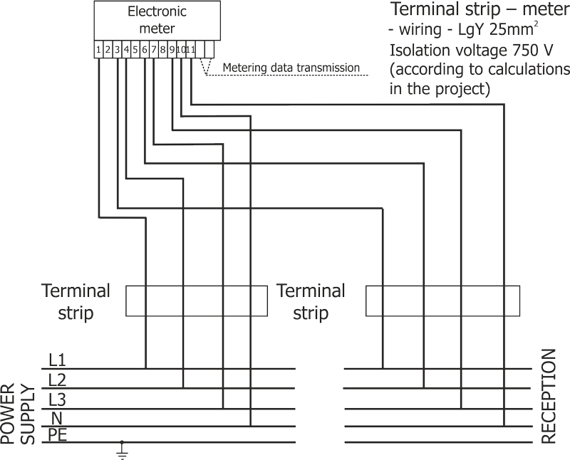
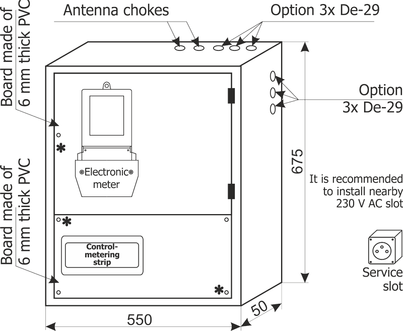
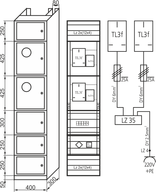
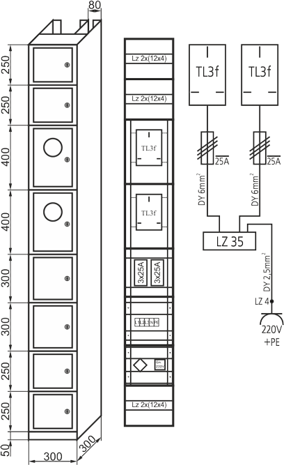
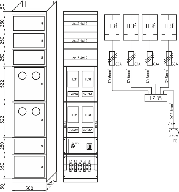
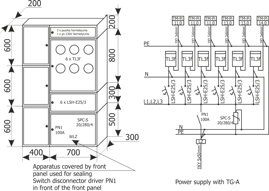
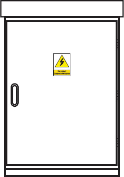
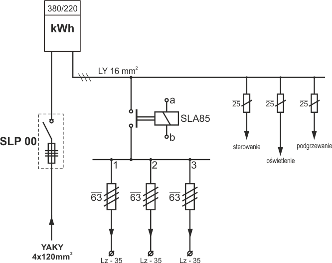
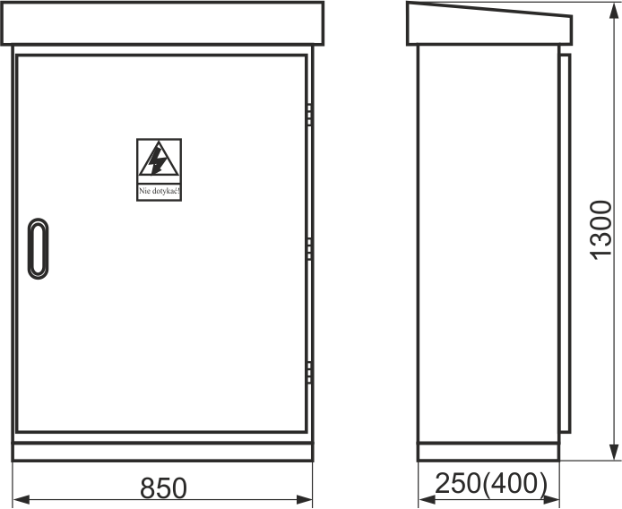
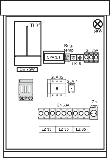
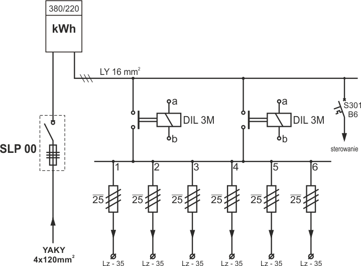
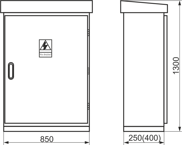
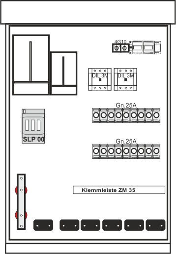
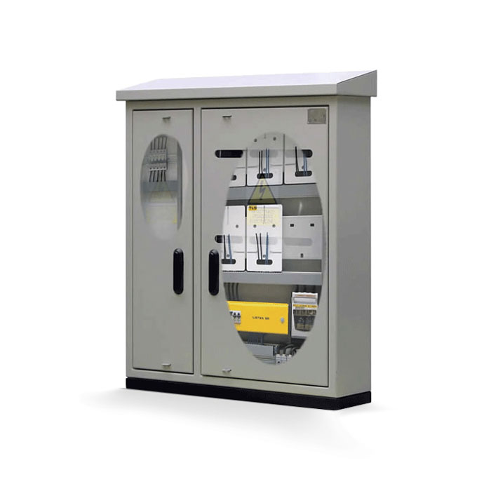
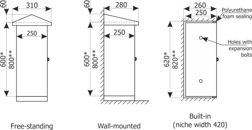
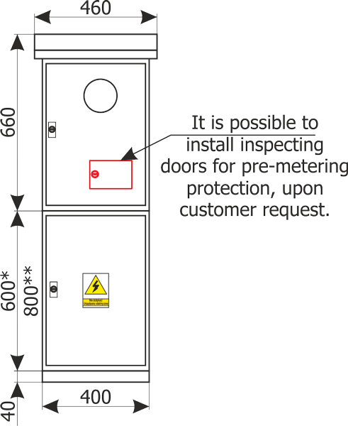
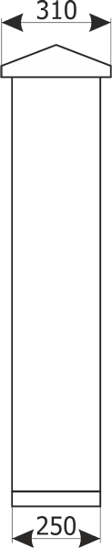
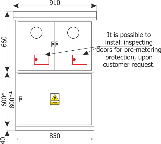
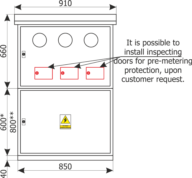
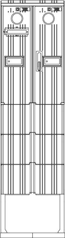
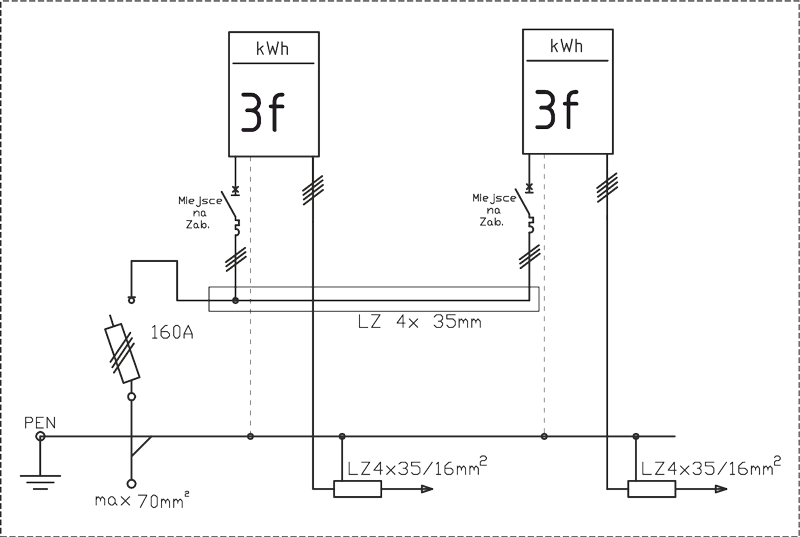
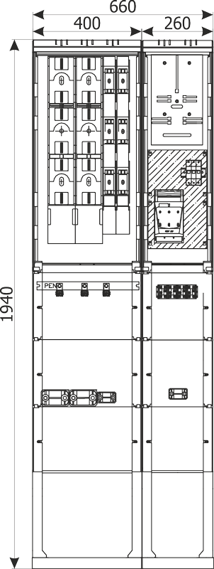
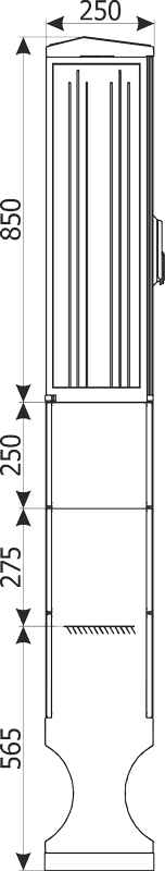
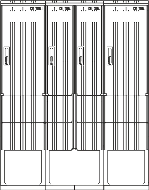
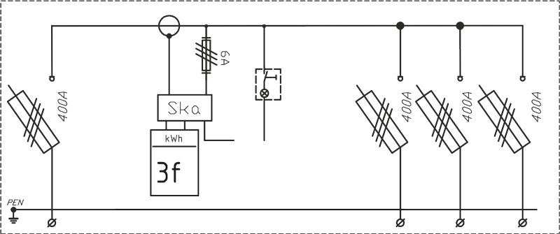
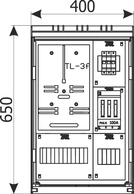
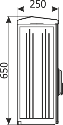
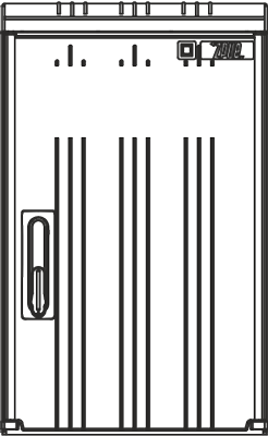
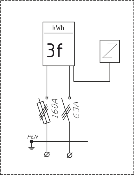
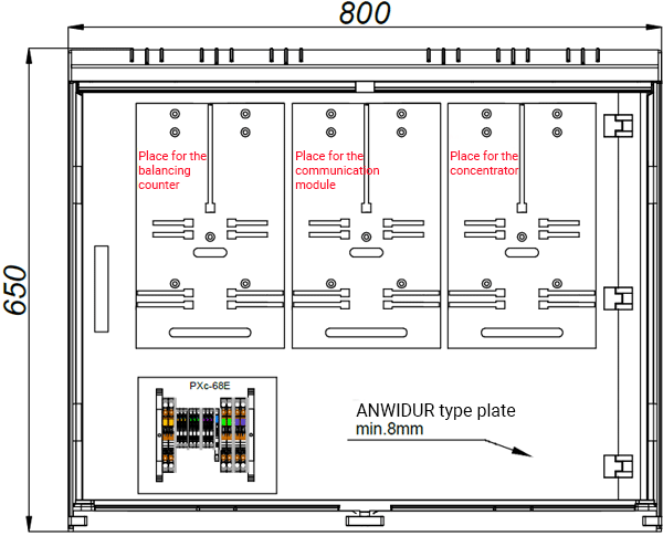
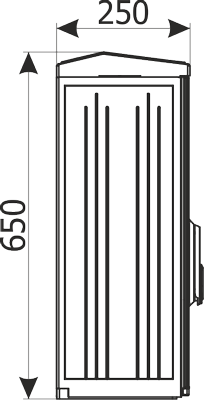
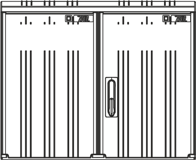
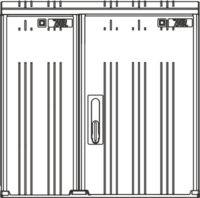
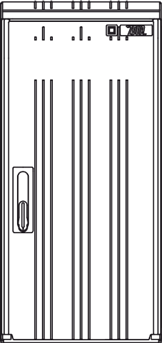
Cable, metering boxes in thermosetting cubicles
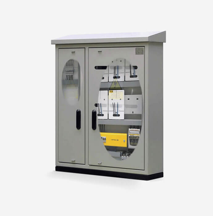
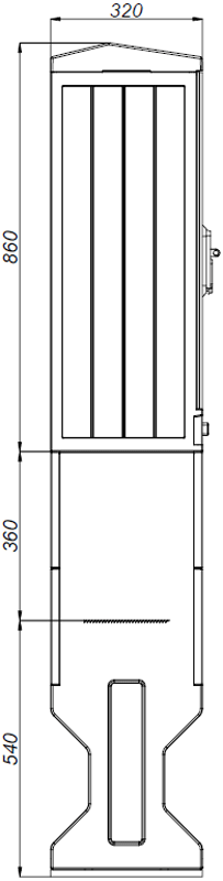
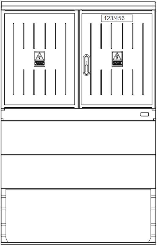
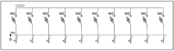
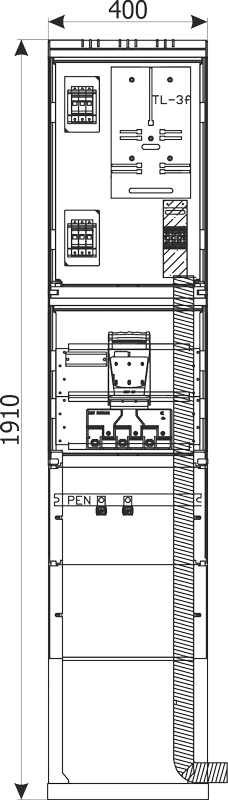
Cable, metering boxes in aluminium cubicles
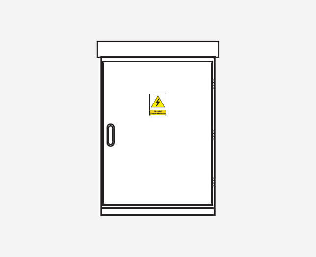
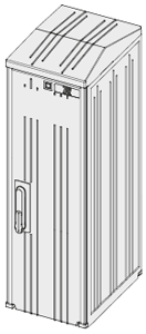
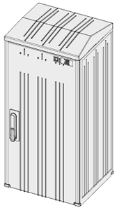
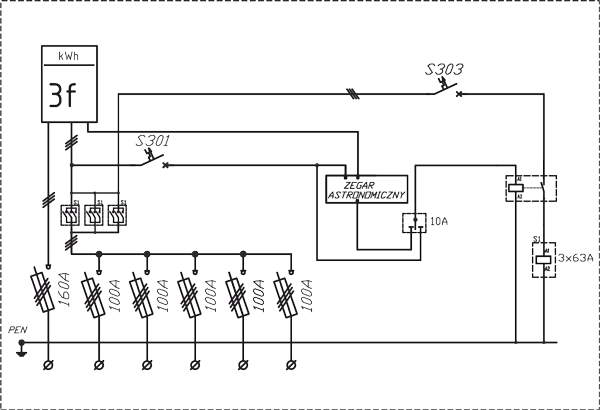
SOU, RSOU - Street lighting cabinets
Other
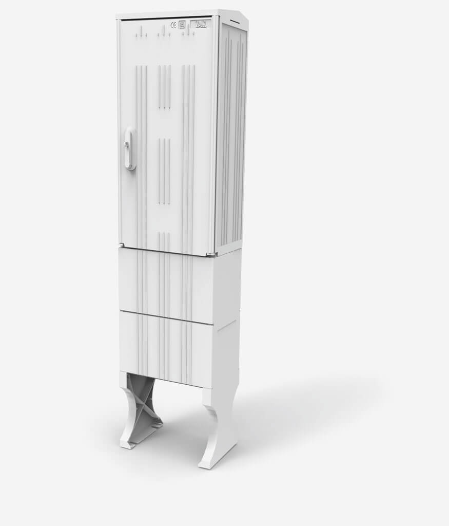
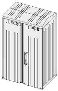
Thermosetting cubicles
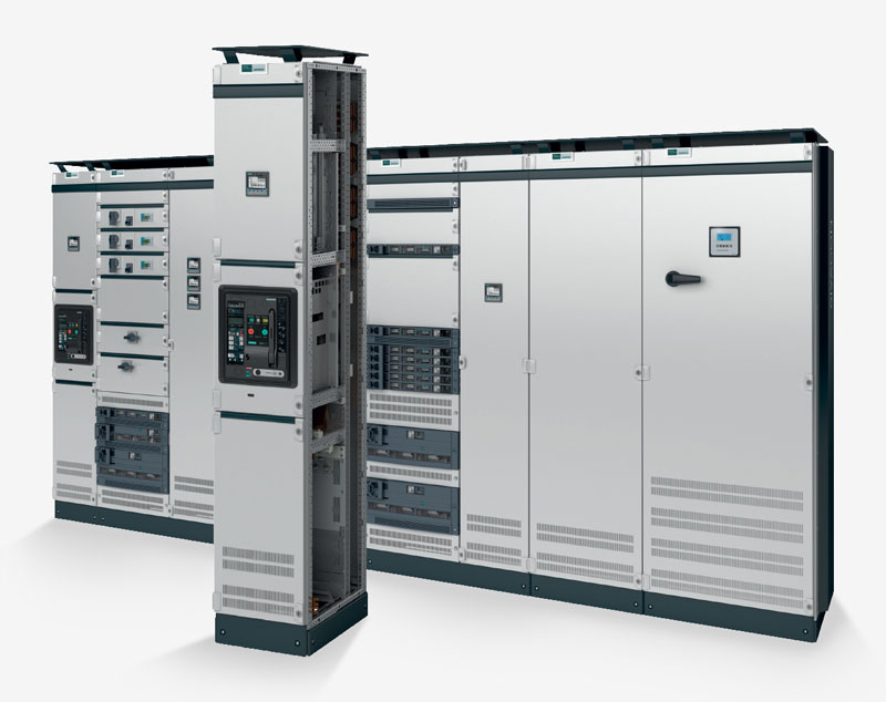
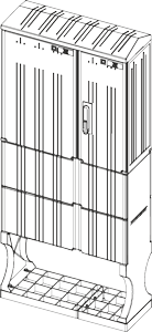
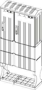
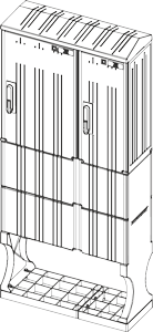
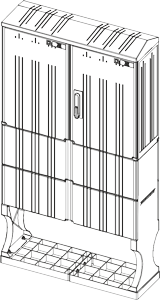
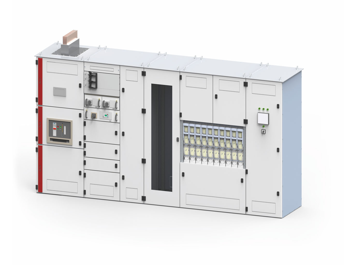
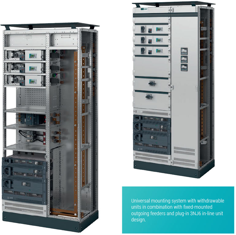
Sivacon S8
What is a switchgear?
Switchgear is a group of electrical power equipment that serves as a set of distribution, protection, measurement, and control. It also includes other equipment, all placed in a special enclosure. In addition to these devices, inside the housing there are, for example, busbars, electrical connections, insulating elements, and covers. The main task of such a structure is the distribution of electricity, as well as the connection and protection of electrical circuit lines. One type of switchgear is low-voltage switchgear.
For which purpose are low-voltage switchgears used?
LV switchgear, or low-voltage switchgear, is designed for the transmission and distribution of electricity, as well as power supply and protection of electrical equipment from the effects of short circuits and overloads. They find their application in municipal and building electrical substations, as well as in industrial plants, department stores, and other public facilities.
Depending on the location of its installation, low-voltage switchgear is divided into an indoor and an outdoor switchgear. All low-voltage switchgear can be equipped with the following:
- Switching apparatus: disconnectors, fuse disconnectors, circuit breakers with manual or motorized drives,
- Measuring apparatus: current and voltage transformers, electricity meters, analyzers of network parameters,
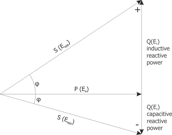
- Reactive power compensation systems,
- Control systems, e.g. lighting,
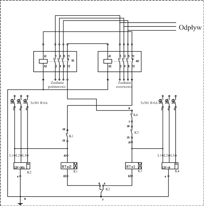
- Systems of automatic reserve switching (SZR).
Technical parameters of switchgears
Low-voltage switchgears, depending on the purpose and functions performed, may differ from one another, mainly in terms of parameters, technical aspects, and the resulting design.
Basic parameters of LV switchgears:
- Un [V] – rated voltage,
- In [A] – rated current,
- Icw [kA] – rated short-circuit withstand current,
- IP / IK degree of protection:
- IP – protection against solid bodies and water ingress,
- IK – protection against mechanical impacts.
Features of ZPUE switchgears
Common features of all ZPUE LV switchgears:
- High operating safety,
- High technical parameters,
- Ability to operate in all low-voltage network systems,
- Flexibility: ability to be equipped with a wide range of apparatus,
- Modular design that allows you to easily expand existing sets and design new ones,
- Long service life,
- Compliance with IEC standards.
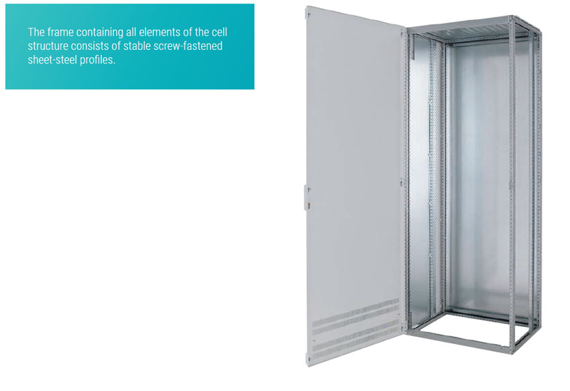
For the safety of the operator and the possibility of a long, trouble-free operation, LV switchgears are equipped as standard with a system of interlocks and shock protection measures. The durability of our switchgears is ensured by a robust metal enclosure made in accordance with the requirements of PN EN 61439-1, whose expected service life under normal operating conditions, indoors, is at least 30 years. The safety of our products is confirmed by the type tests performed on independent accredited testing units.
It is worth noting that ZPUE S.A. provides comprehensive solutions, from switchgear design to manufacture. Each supplied switchgear is properly tailored to the customer's needs. This is what makes us stand out in the market. All switchgears produced by ZPUE S.A., thanks to well thought-out solutions, are adapted to cooperate with all available SCADA systems.
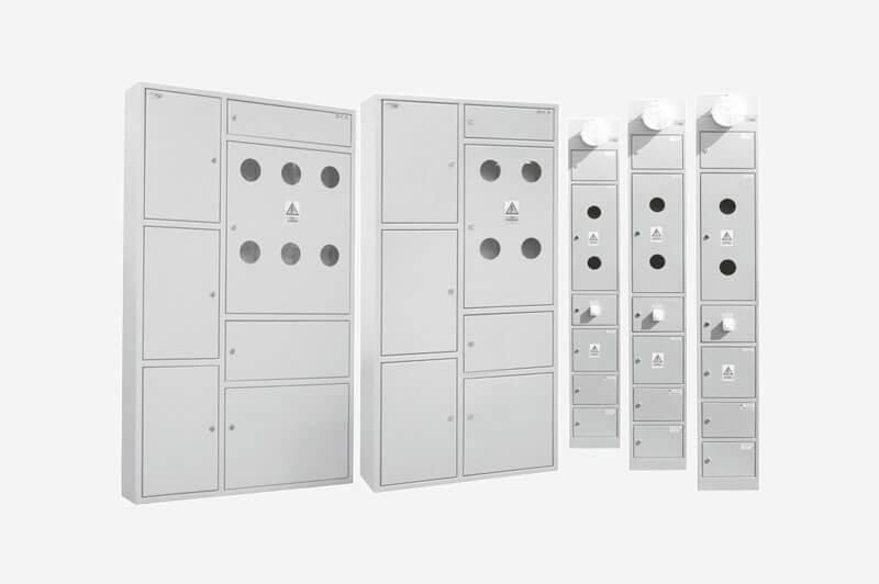
Examples of ZPUE LV switchgears
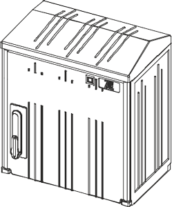
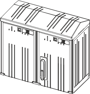
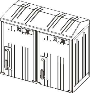
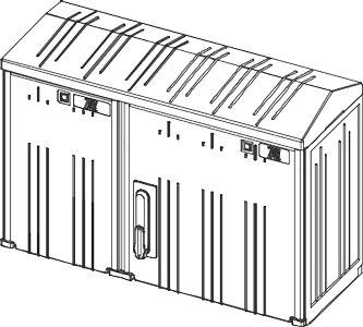
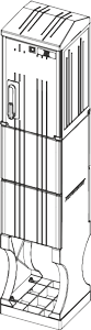
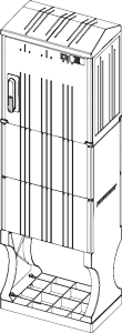
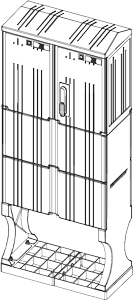
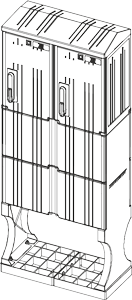
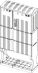
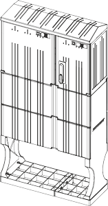
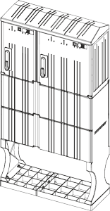
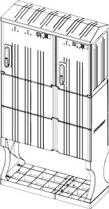
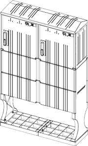
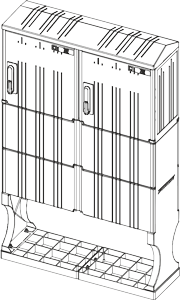
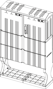
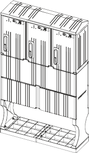
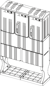
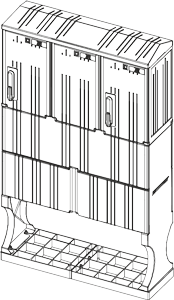
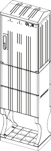
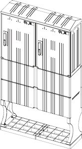
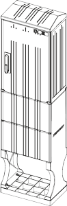
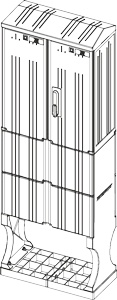
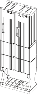
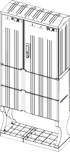
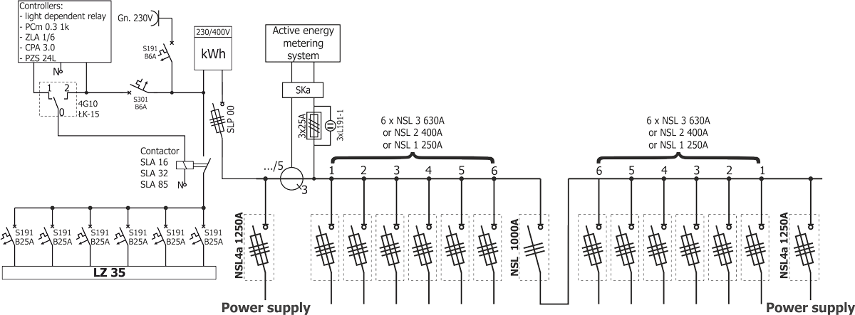
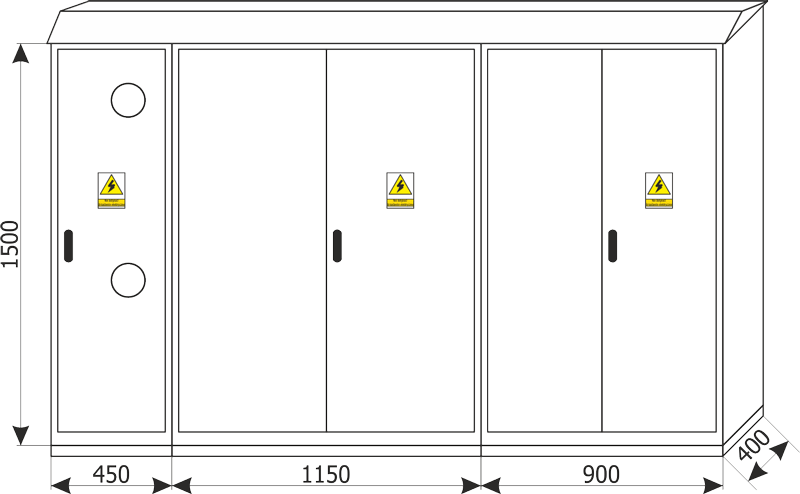
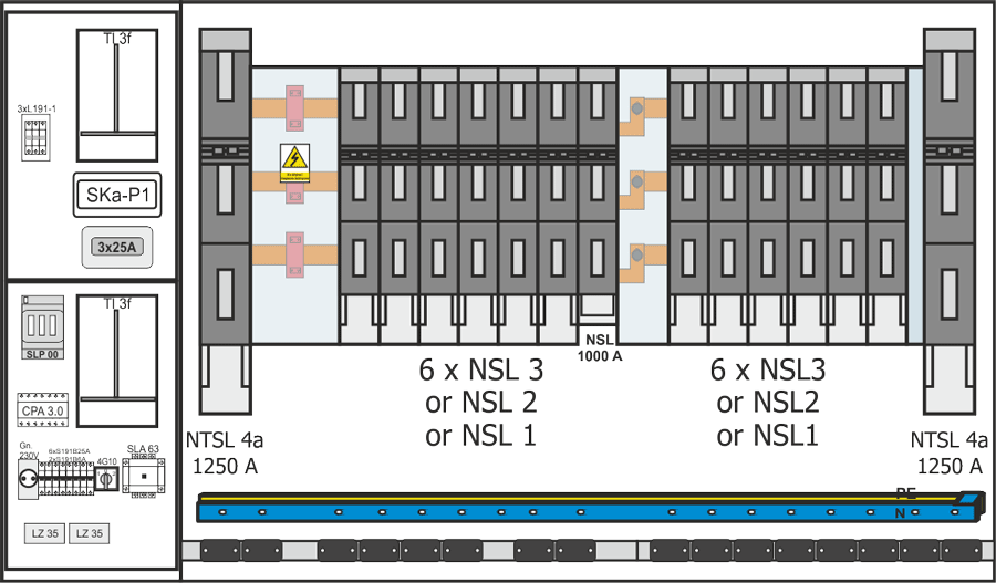
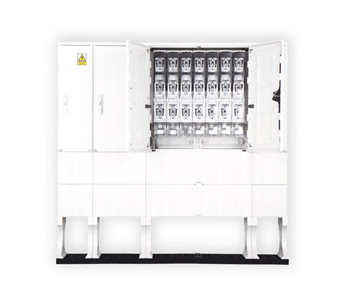
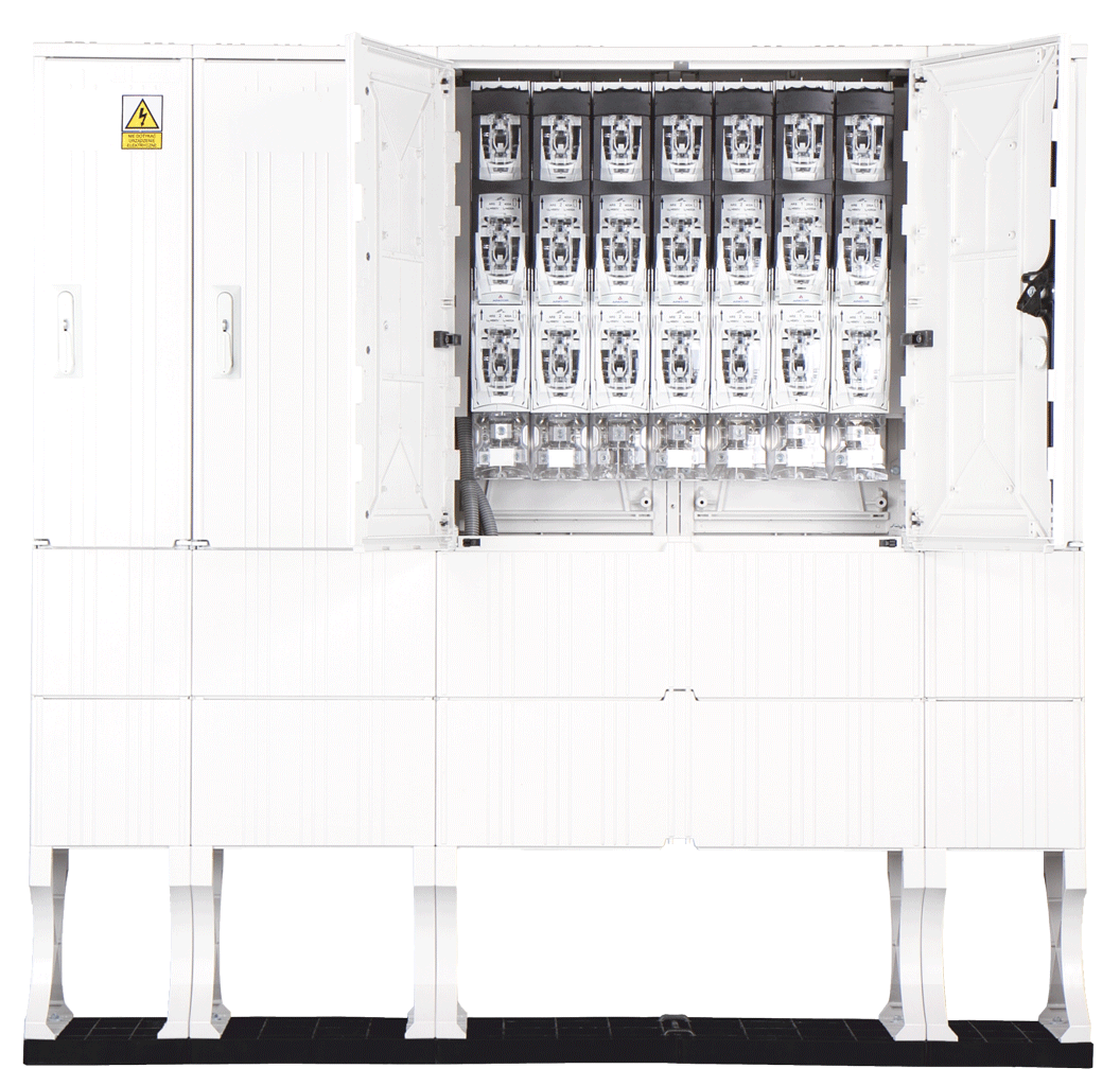
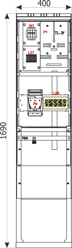
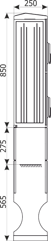
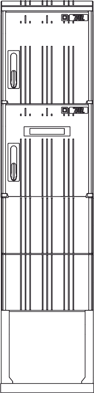
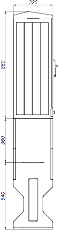
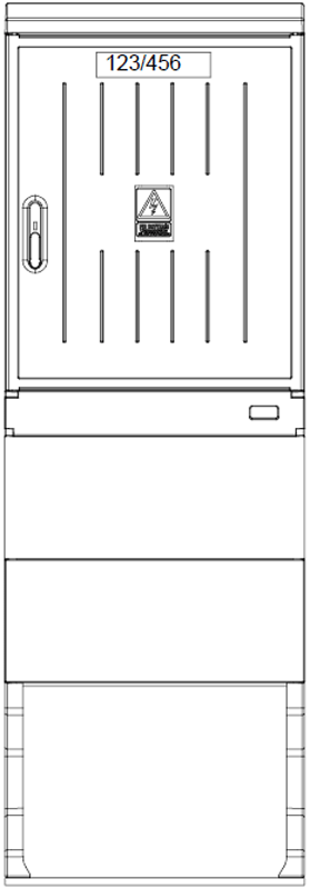
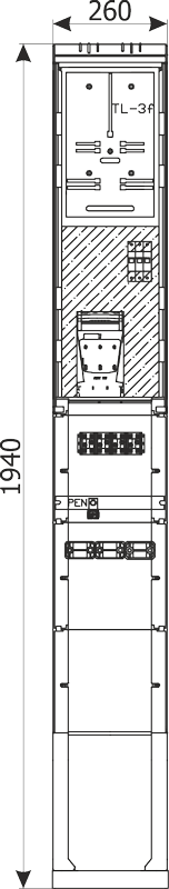
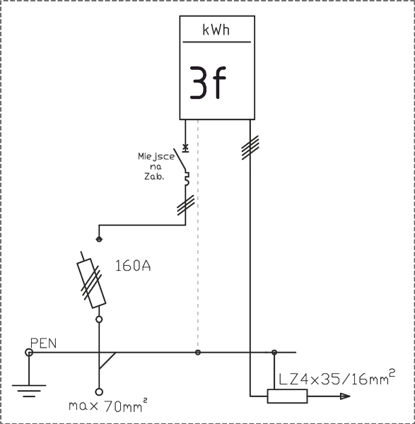
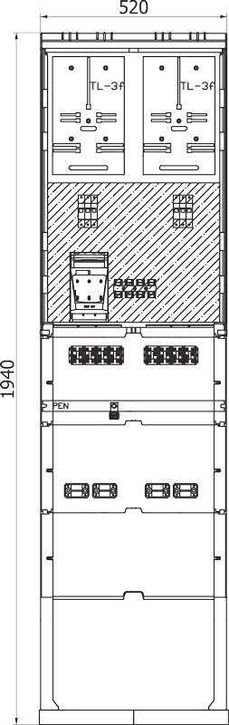
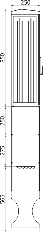
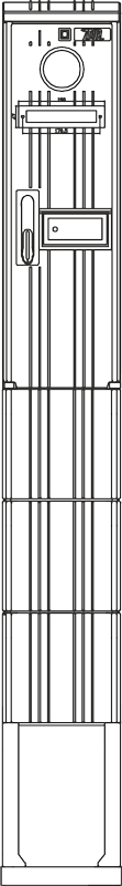
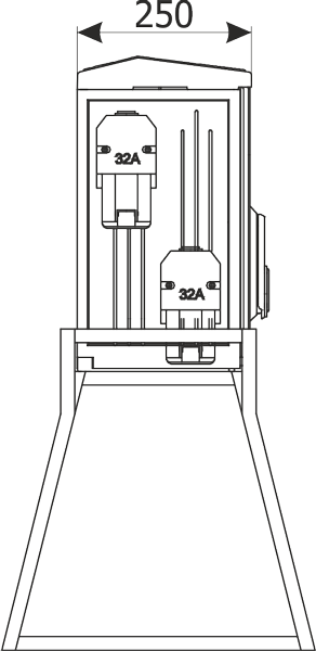
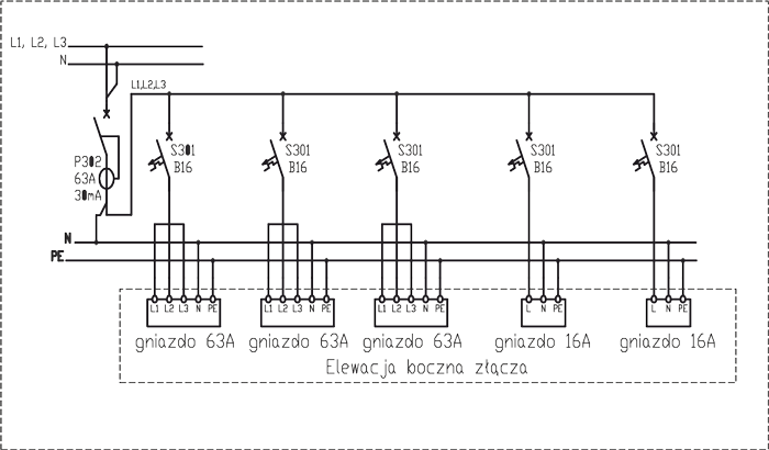
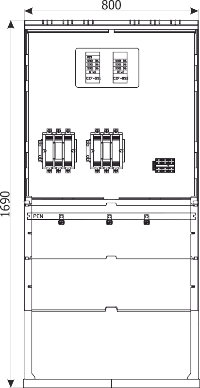
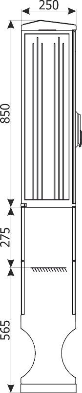
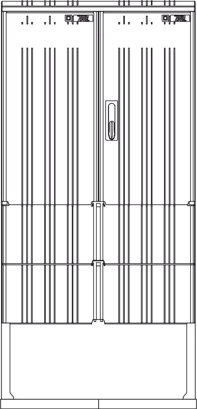
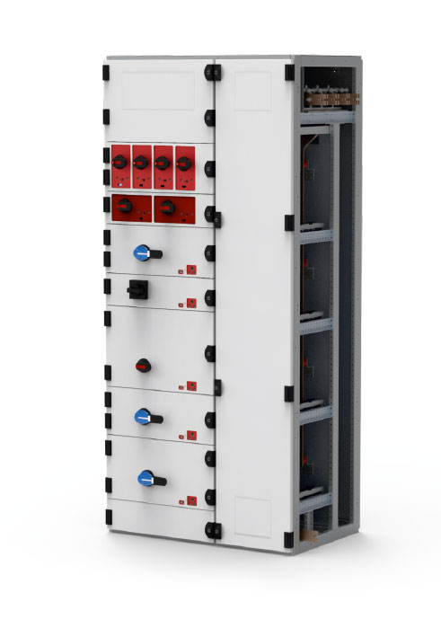
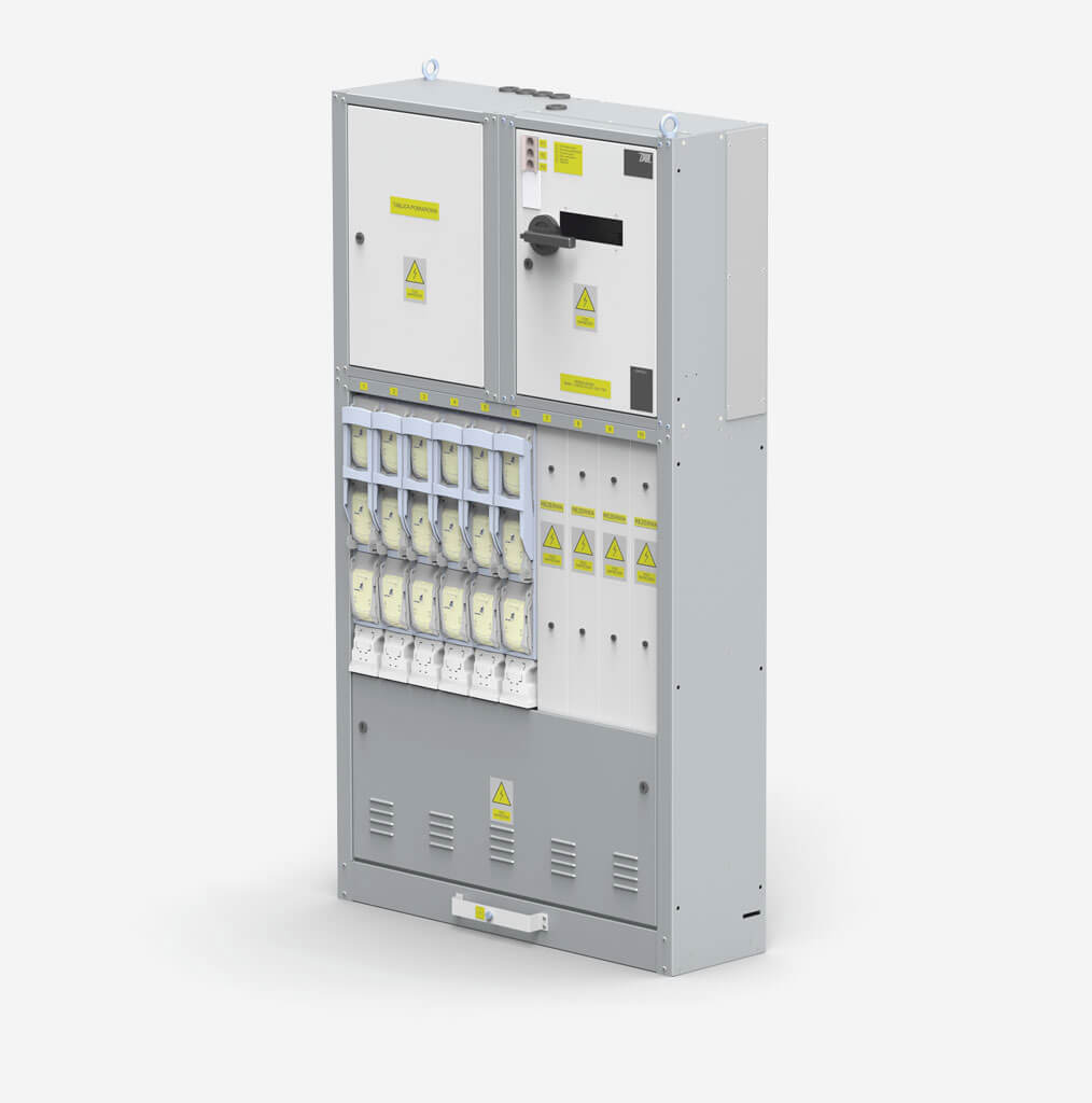
We offer a complete set of low-voltage solutions manufactured for industrial facilities, shopping centers, urban areas, as well as for other applications. The compact RN-W low-voltage switchgear has a modular design, which makes it easy to expand and adapt to specific requirements. Additionally, thanks to a special interlocking system, fuse replacement and other maintenance work can be carried out quickly and safely.
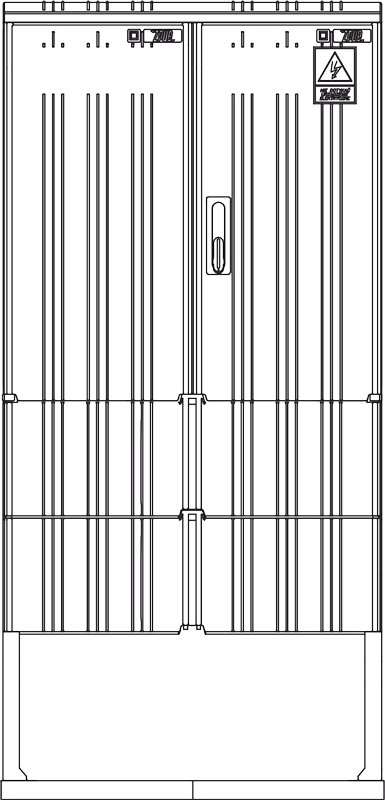
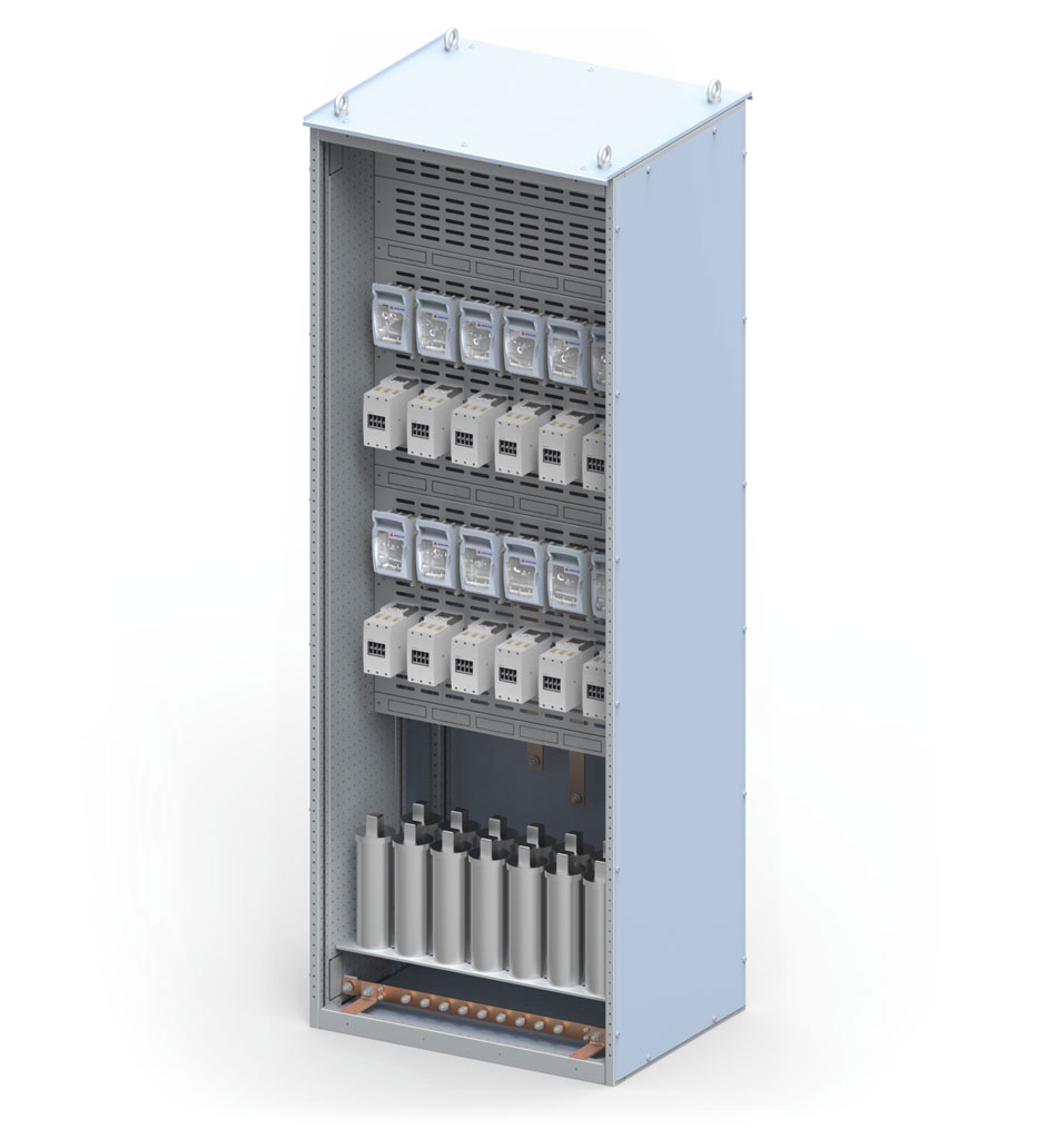
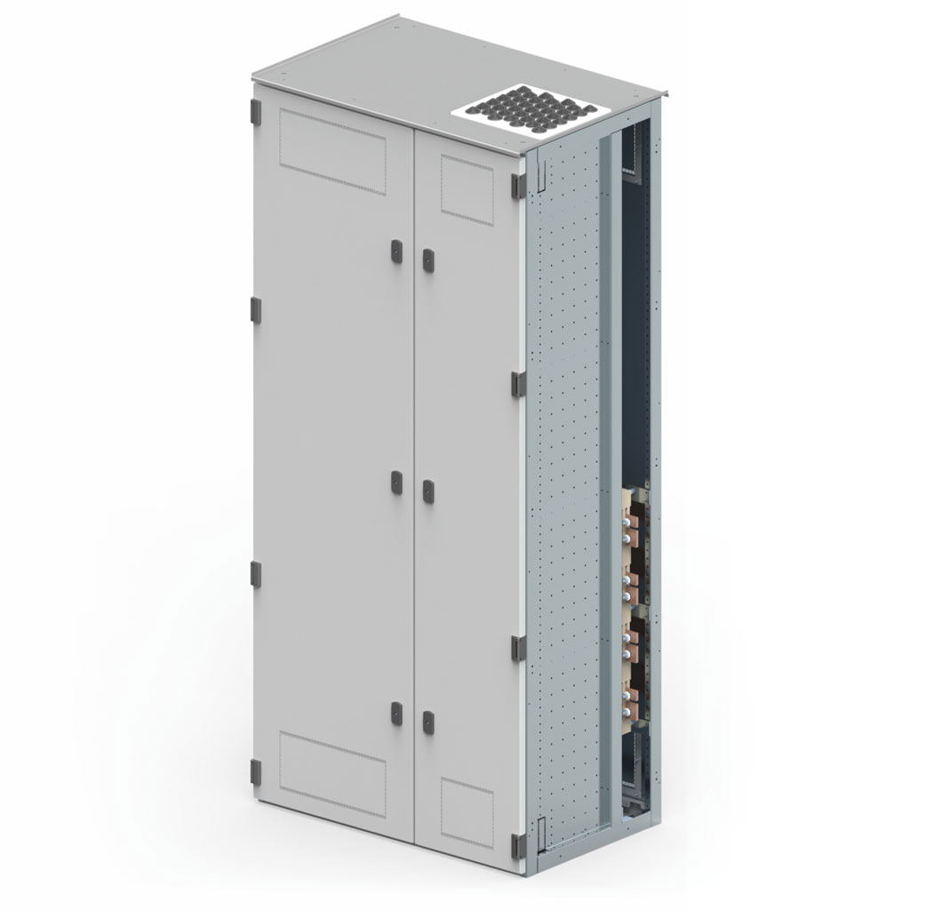
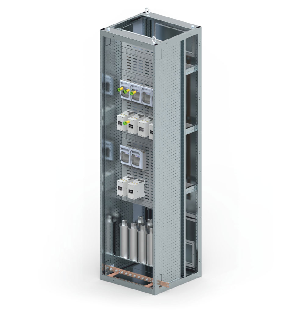
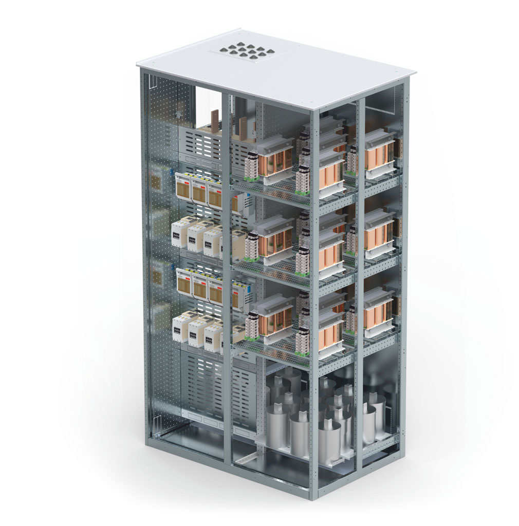
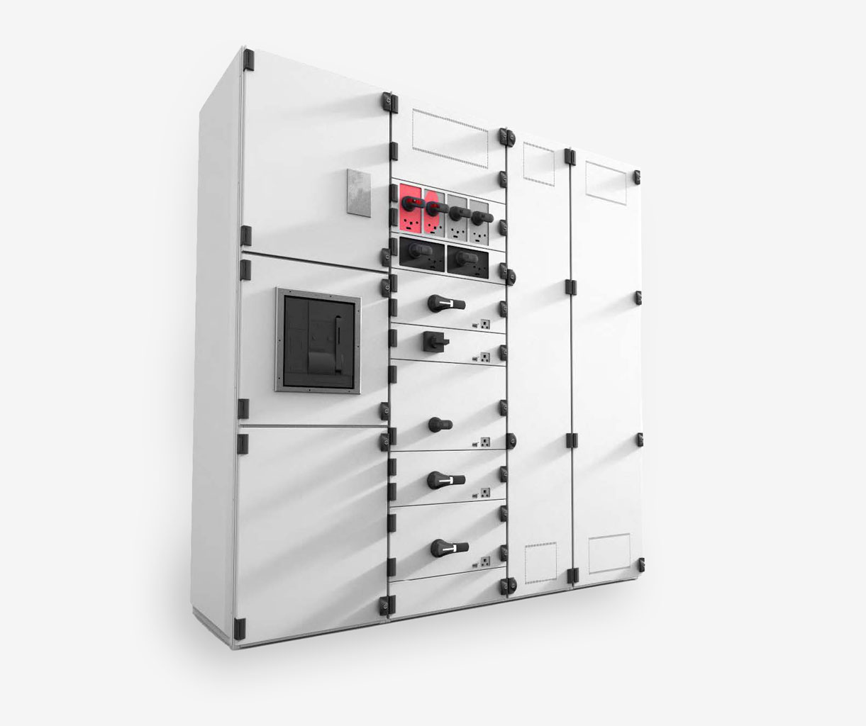
ZPUE ZR-W switchgear is designed for power distribution in various industrial facilities: pharmaceutical, chemical, steel mills, and others. It is also used at airports, hospitals, shopping malls, etc. Its design allows for simple installation, easy replacement of modules, and trouble-free expansion of the entire system.
Our range of low-voltage switchgears also includes cable, metering, and aluminum boxes, thermoset boxes, and other solutions for the energy sector.
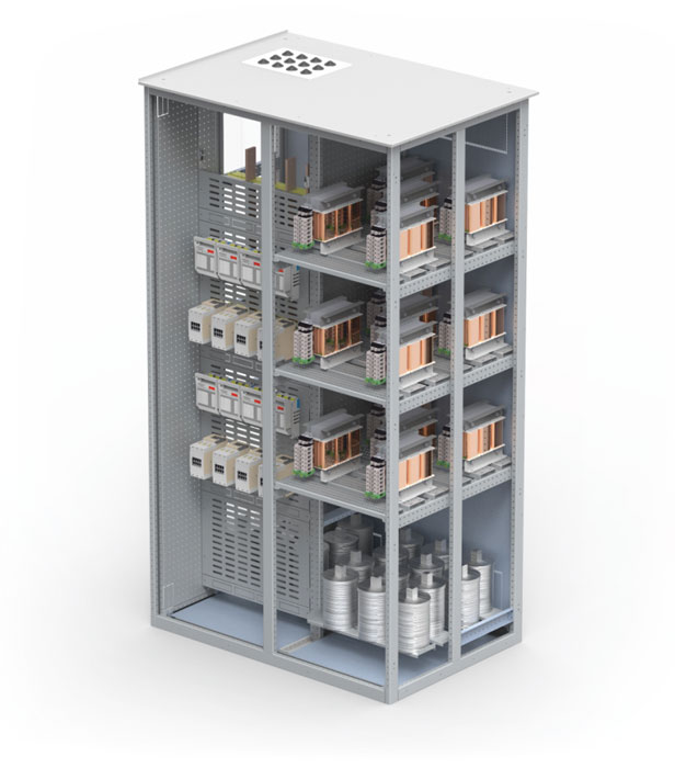
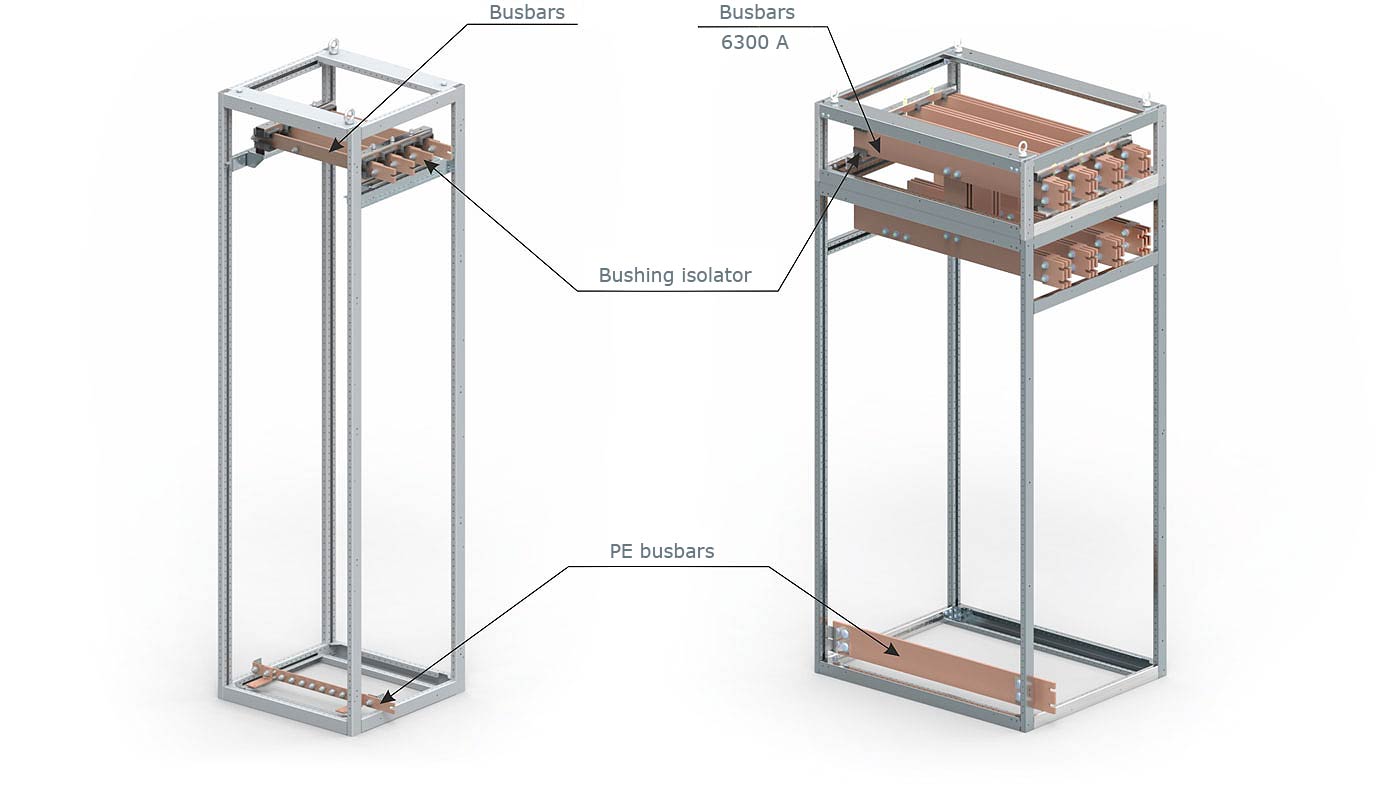
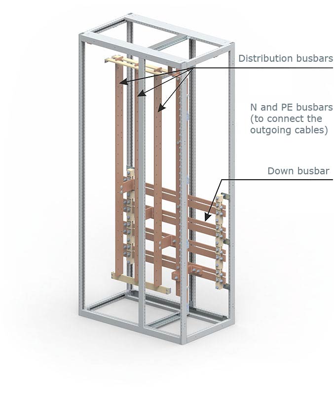
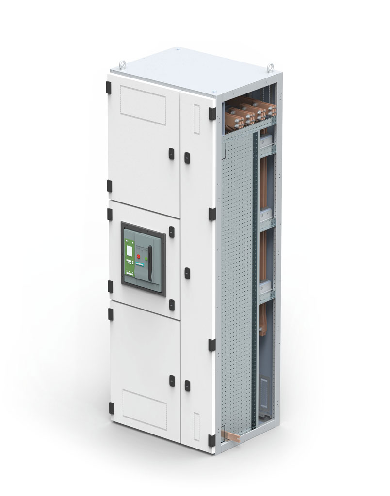
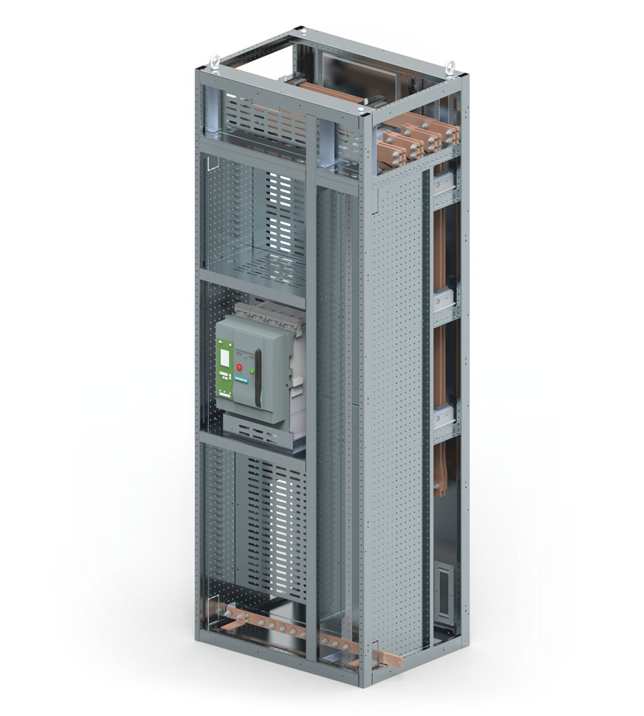
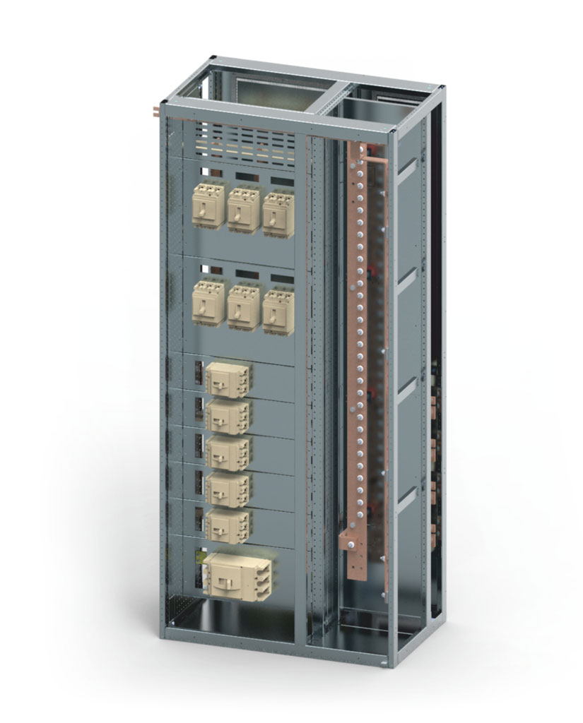
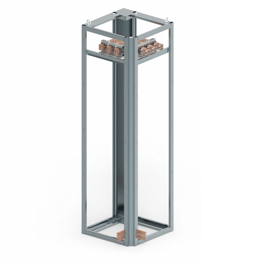
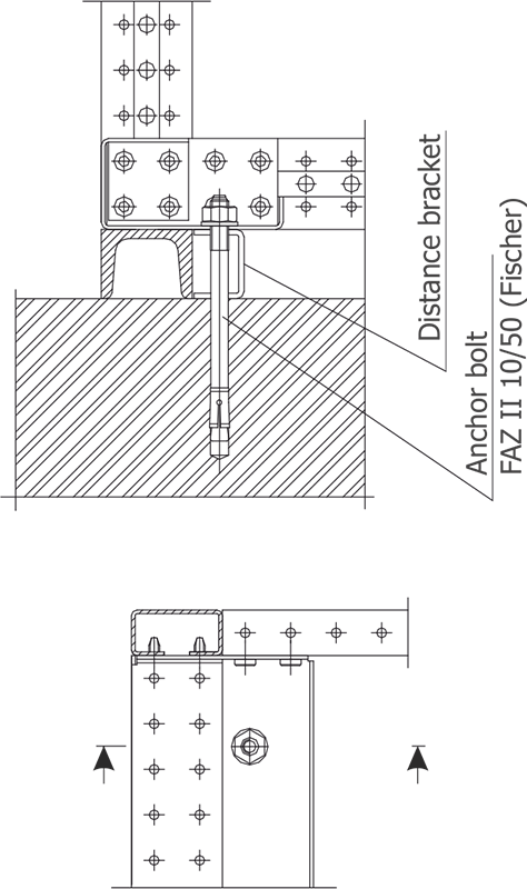
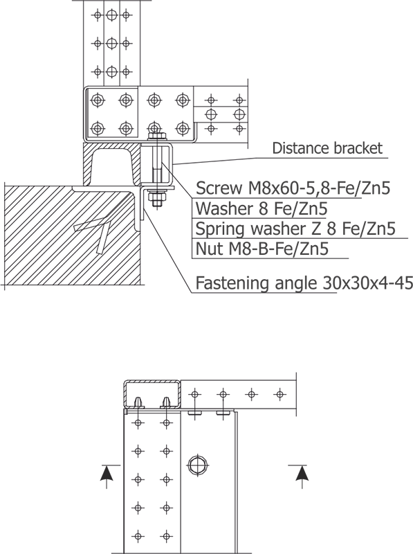
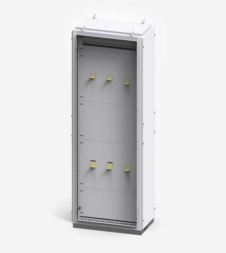
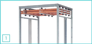 1. Position of the main busbars at the top up to 6300 A.
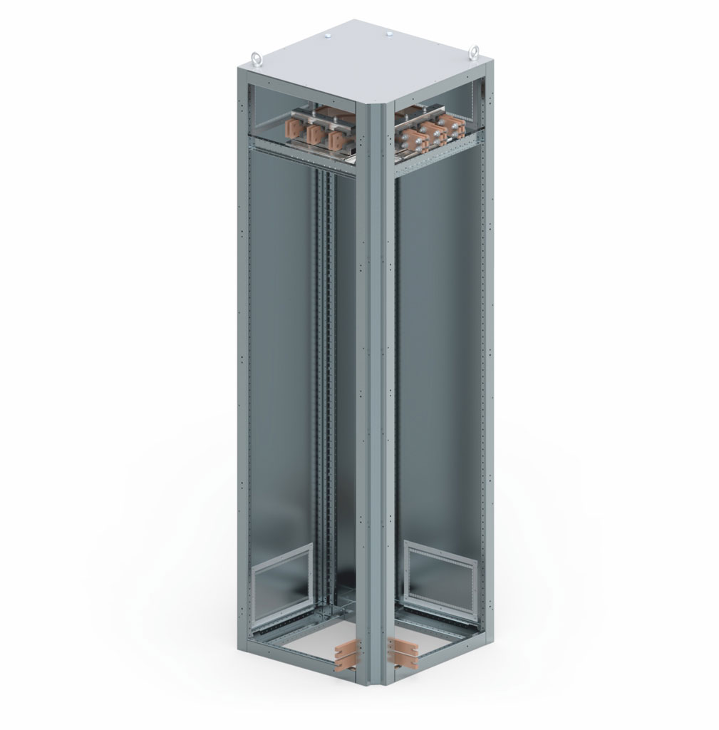
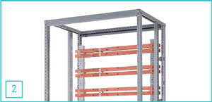 2. Variable rear busbar position up to 7000 A (top and/or bottom).
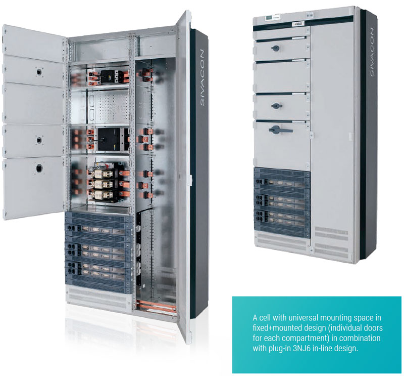
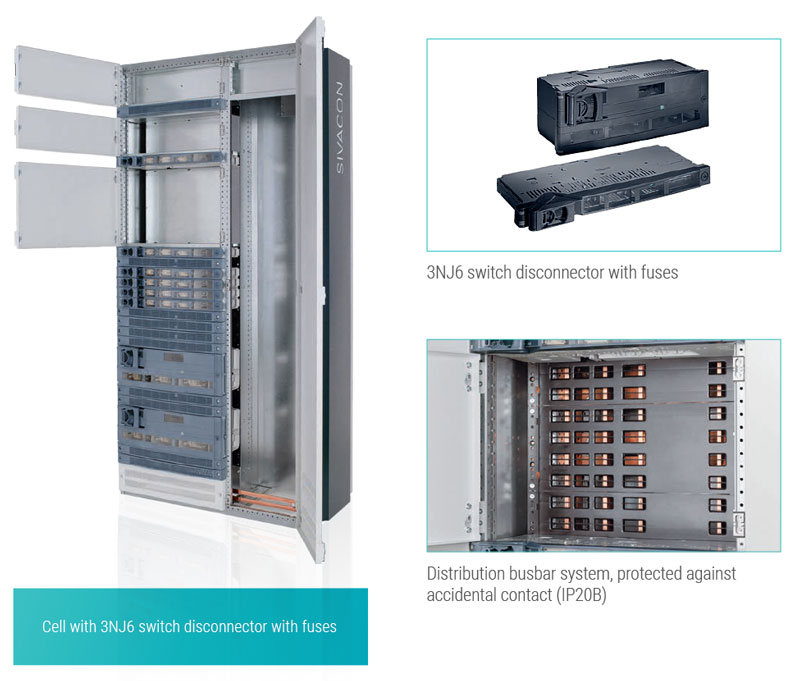
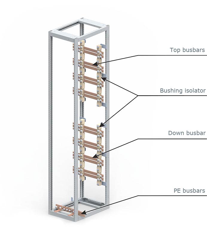
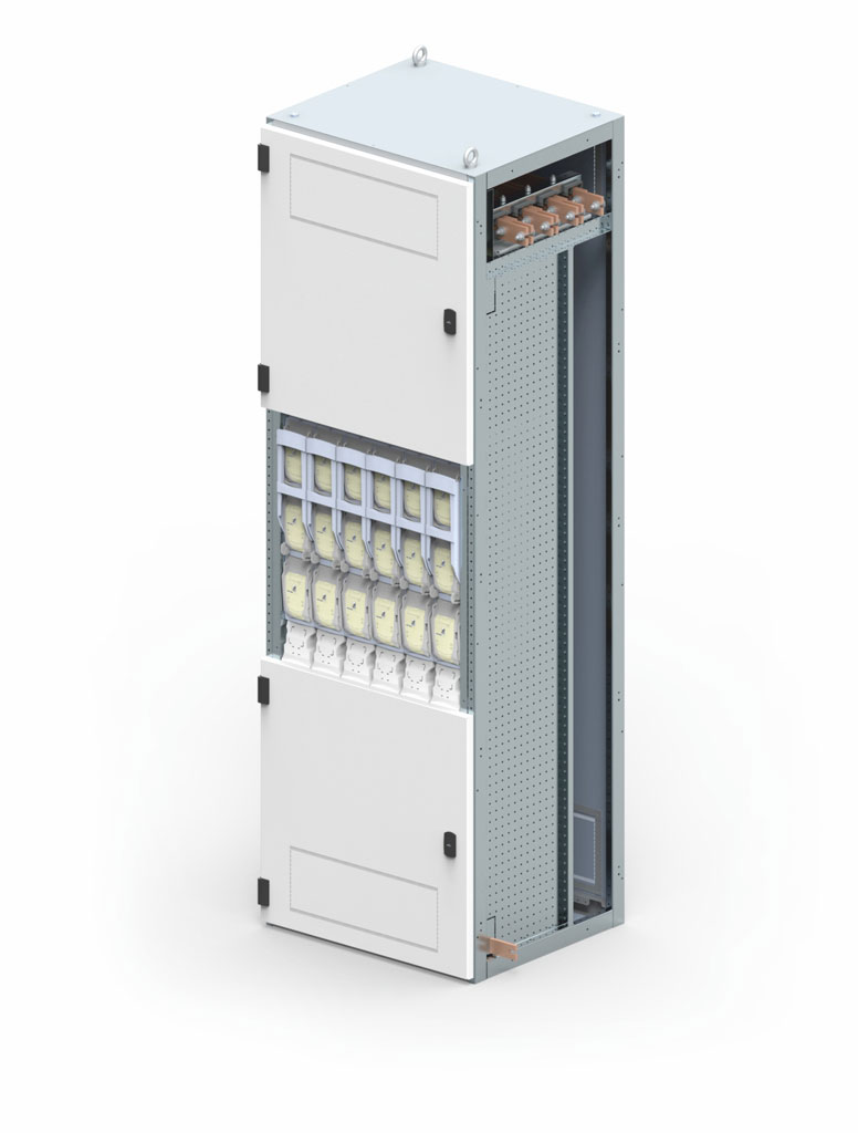
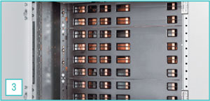 3. Plug-in busbar system with contact protection, cover (IP 20B) for quick and easy replacement of fuse switch disconnectors.
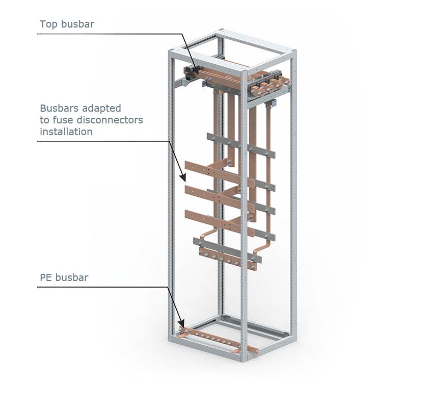
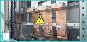 4. Optimal connection conditions in the busbar connection compartment.
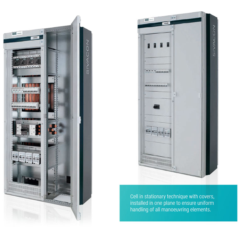
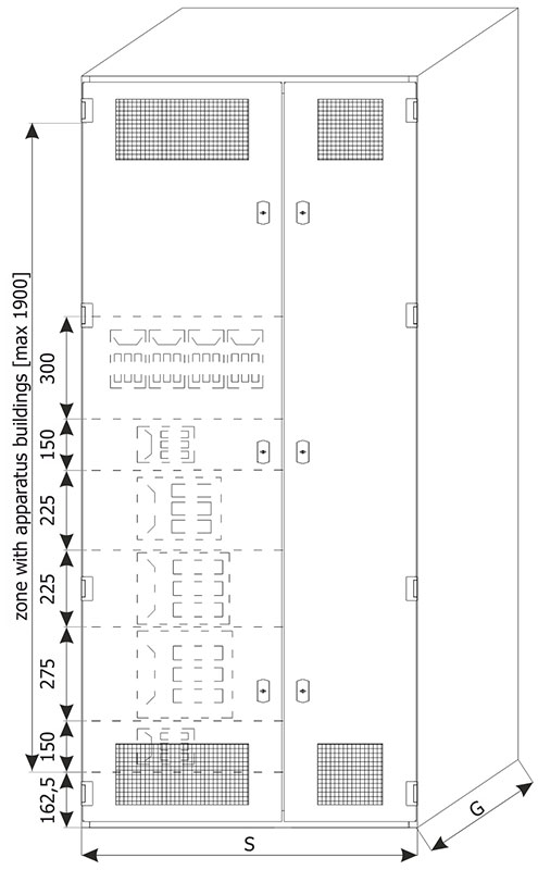
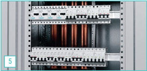 5. Multi-profile busbars allow easy assembly of modular installation devices.
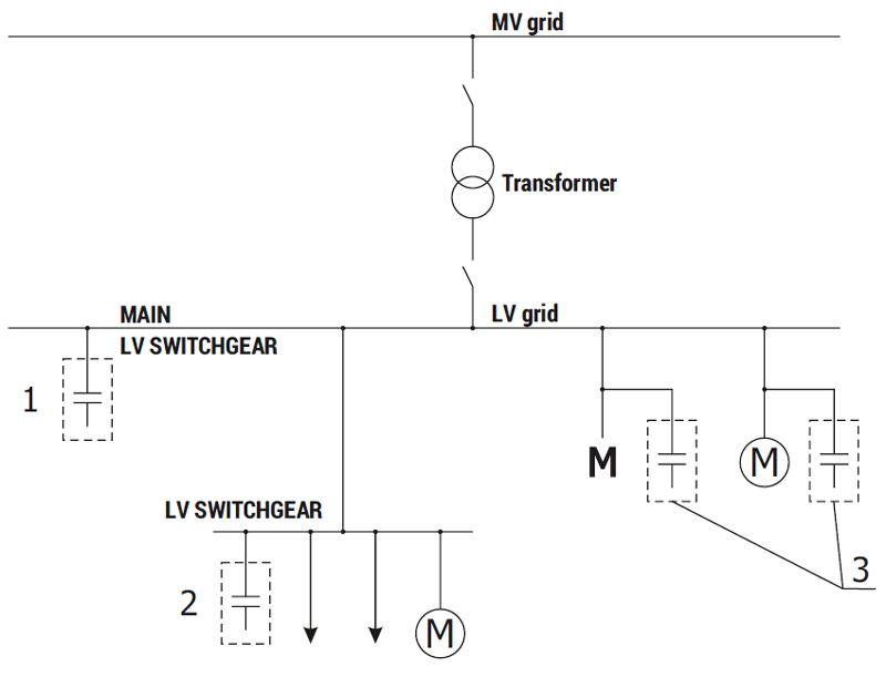
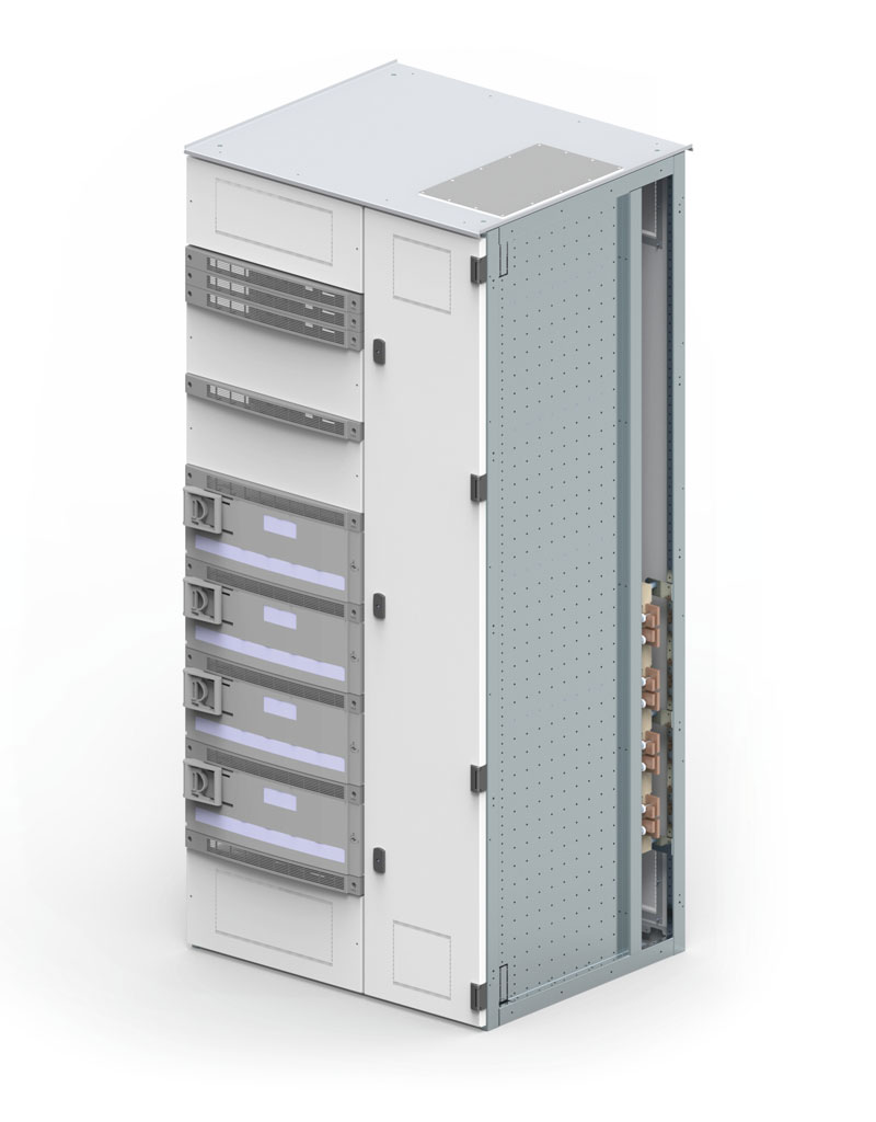
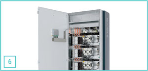 6. Cells with reactive power compensation with design verification according to PN-EN 61439 reduce transmission losses.
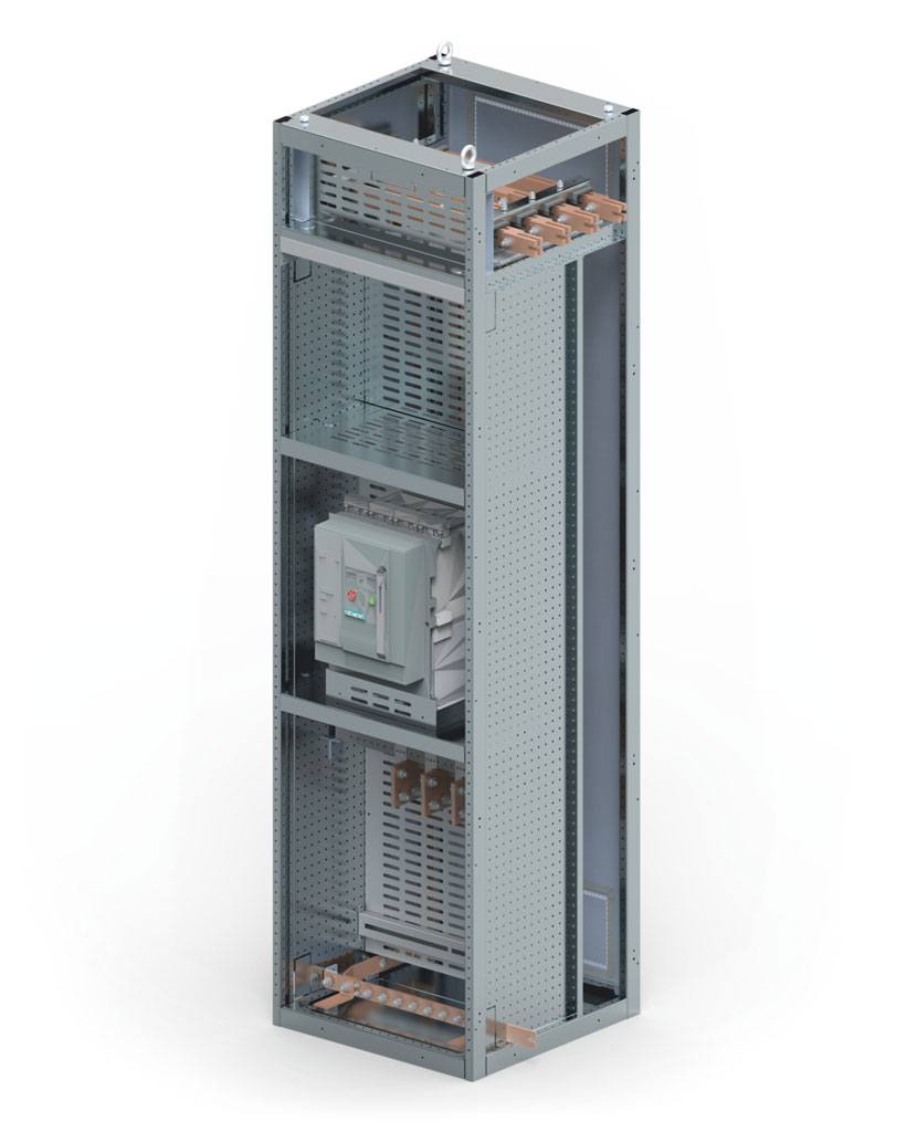
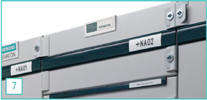 7. Overview of power distribution thanks to a standardized labeling system for sections and feeders.
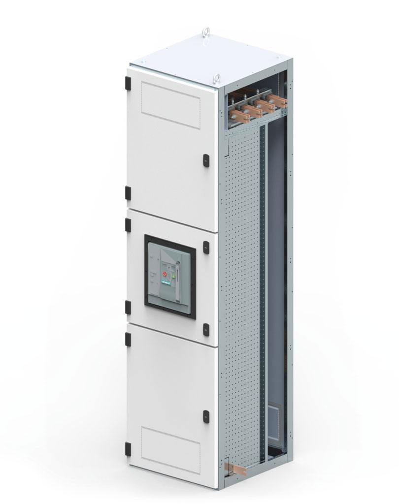
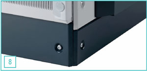 8. A modern look with design elements like the side panel and optionally extendable base.
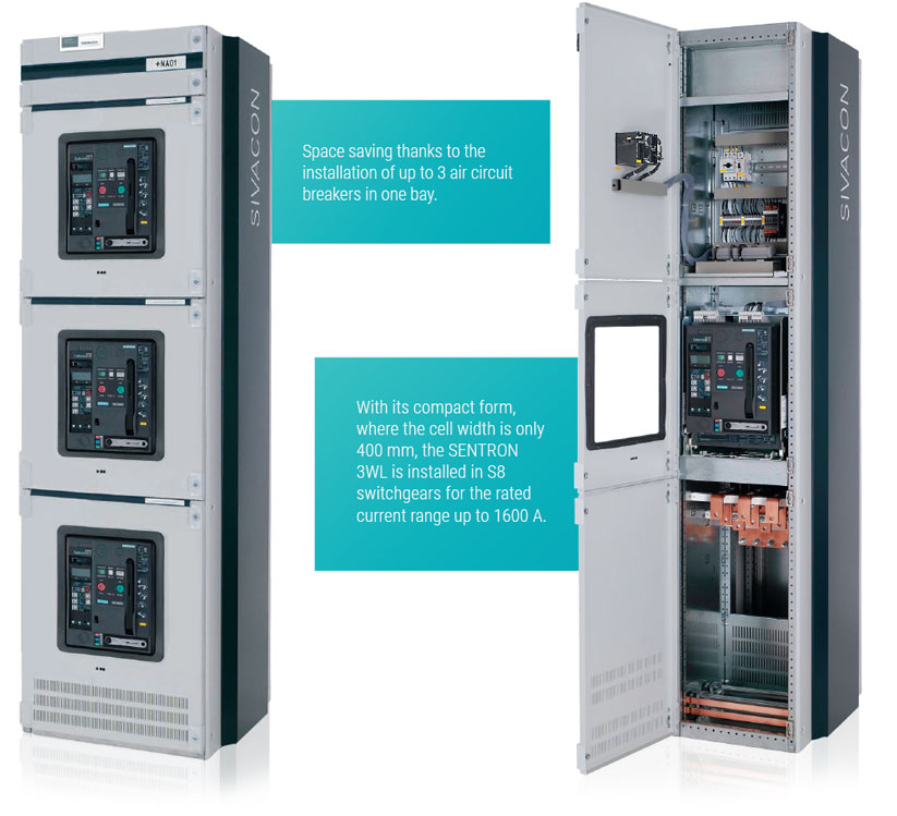
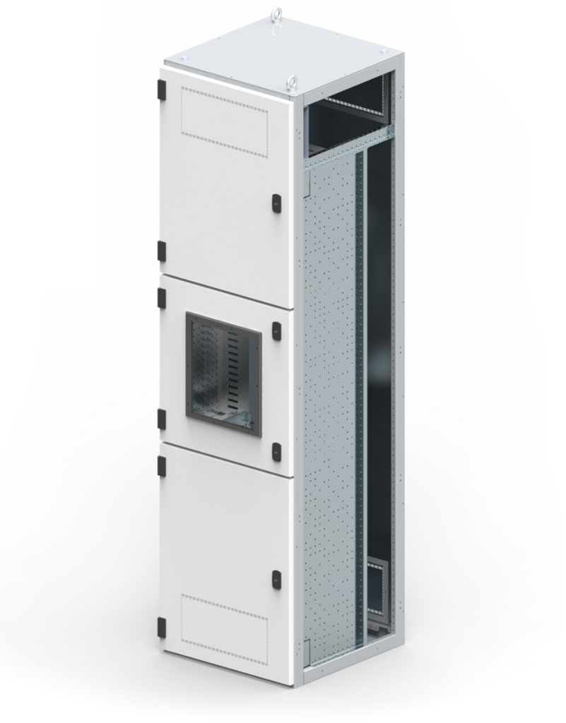
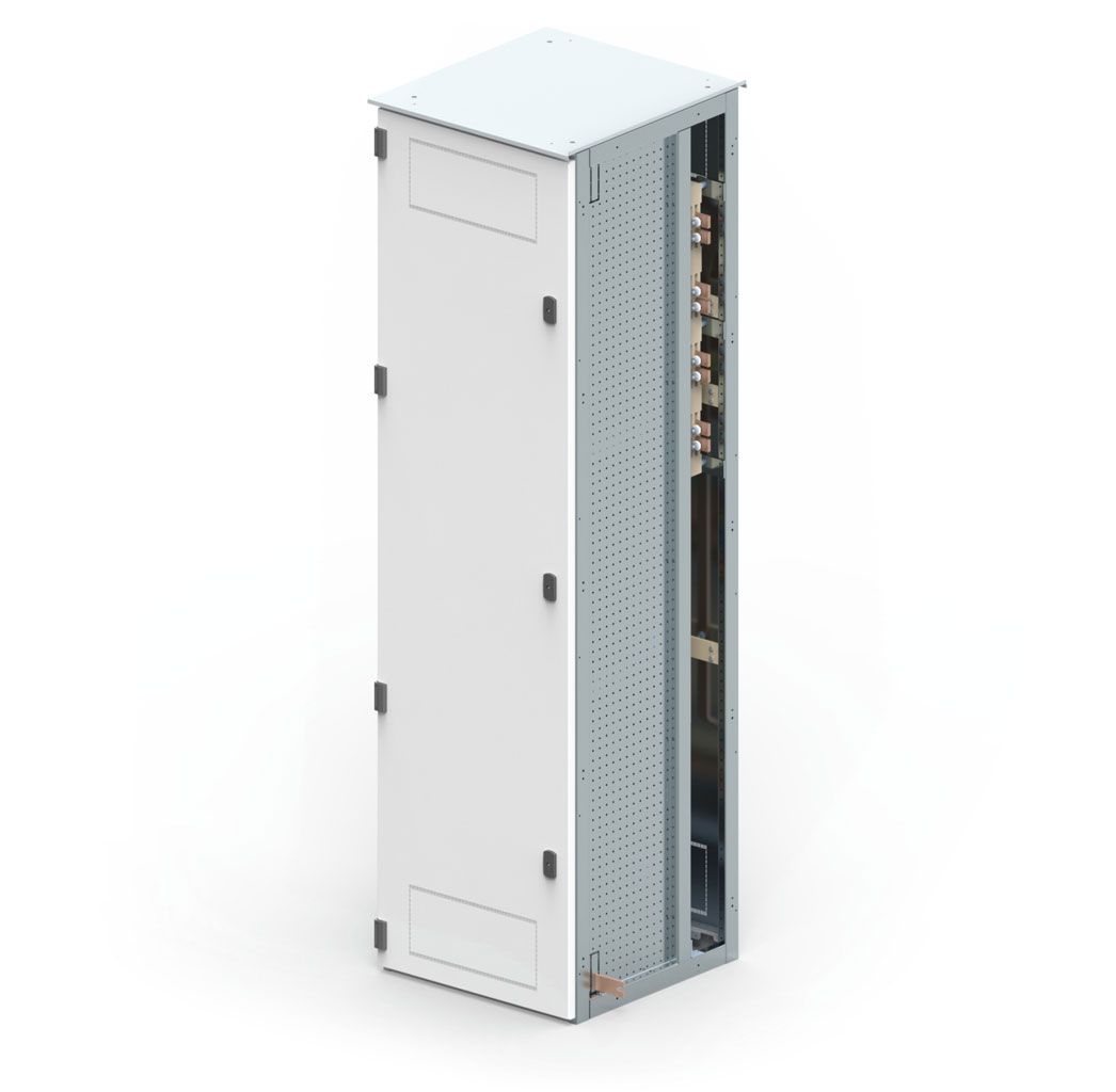
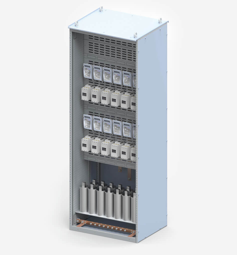
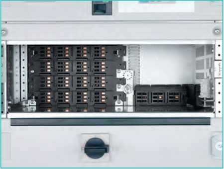 Rear plug-in busbar system
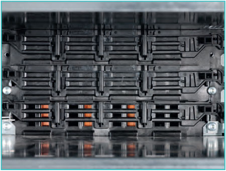 Optional with shutter
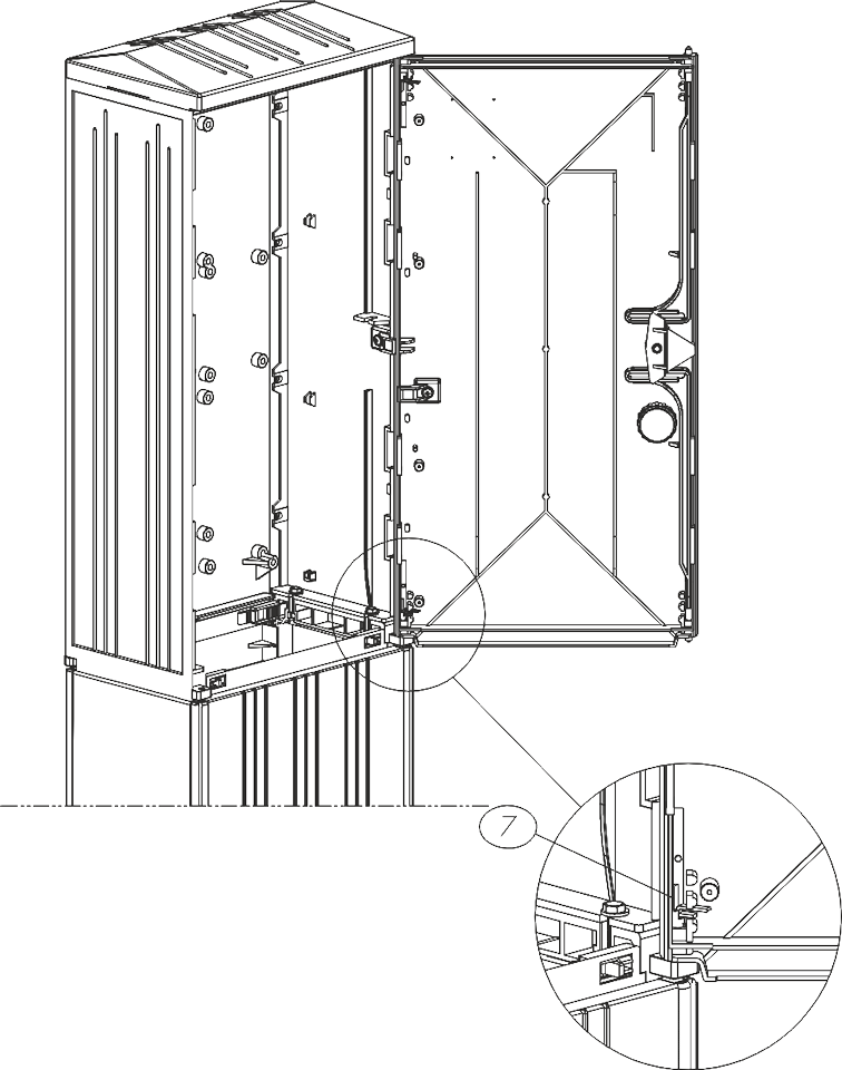
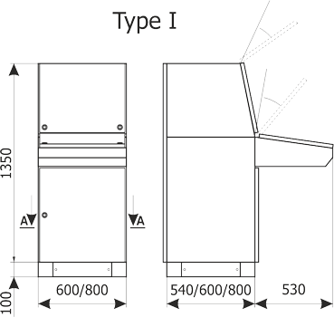
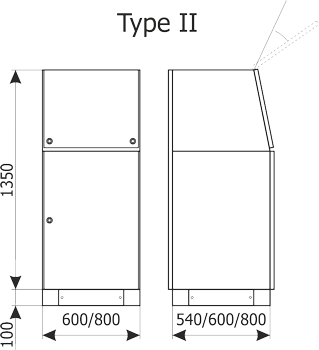
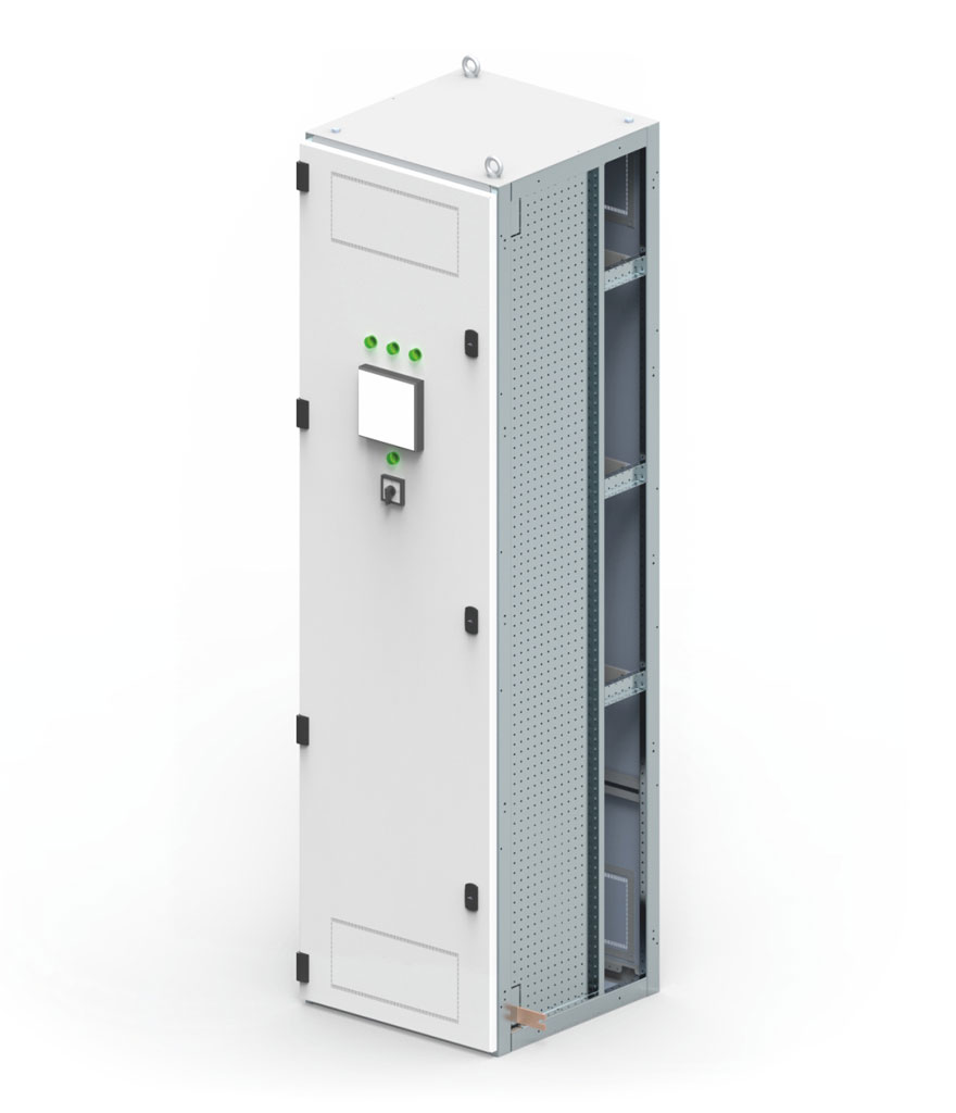
 Hinged panel for mounting control and signalling devices in order to perform service works during work.