What is a switchgear?

Switchgear is a group of electric power equipment that serves as a set of distribution, protection, measurement, and control.It also includes other equipment, all placed in a special enclosure. In addition to these devices, inside the enclosure there are, for example, busbars, electrical connections, insulating elements, and covers. The main task of such a structure is the distribution of electricity, as well as the connection and protection of electrical circuit lines. One type of switchgear is medium-voltage switchgear.

Characteristics of MV switchgears

MV switchgear, or medium-voltage switchgear, is equipment whose rated voltage, according to IEC 62271-200, is from 1 kV to 52 kV. However, in practice, the most common voltage ratings are 7.2 kV, 12 kV, 17.5 kV, 24 kV, and 36 kV. Medium-voltage switchgears are designed for the transmission and distribution of electricity, as well as power supply and protection of electrical equipment from the effects of short circuits and overloads. Medium-voltage switchgears also have the task of supplying low-voltage networks through MV/nN transformers. Medium voltage can also be used directly to supply power to high-power electrical machinery, as well as railroad catenary lines.

Rated parameters of medium-voltage switchgears

The basic rating parameters of MV switchgears include:

  • Ur [kV] – rated voltage,
  • Ir [A] – rated continuous current,
  • Ik (1s or 3s) [kA/s] – rated short-circuit withstand current,
  • Ip [kA] – 2.5x Ik for 50Hz network frequency - rated peak current withstanding,
  • IA [kA/s] – resistance to internal arc,
  • IAC class (Internal Arc Classification) - short-circuit resistance of enclosure sides [AF; AFL; AFLR], F- front, L-sides, R-back,
  • - IP / IK degree of protection:
    • IP – protection against solid objects and water ingress,
    • IK – protection against mechanical impact,
  • LSC (Loss of Service Continuity) category, [LSC1; LSC2; LSC2A; LSC2B],
  • Partition class [PM, PI]:
    • PM – metal partitions,
    • PI – insulating partitions.

The parameters of MV switchgears are selected in accordance with PN-EN IEC 62271-200:2022-02 "High-voltage switchgear and controlgear. Part 200: A.C. switchgear in metal sheaths for rated voltages above 1 kV up to and including 52 kV".

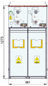
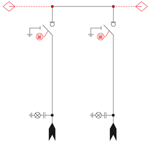
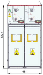
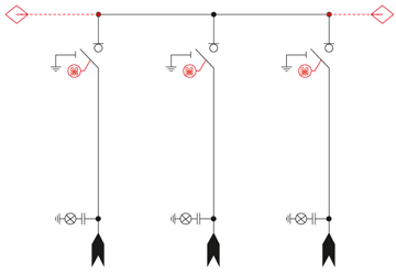
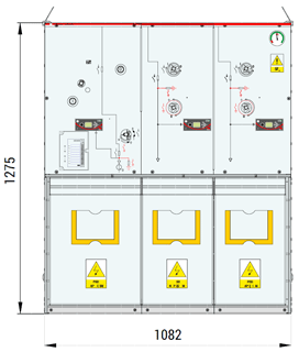
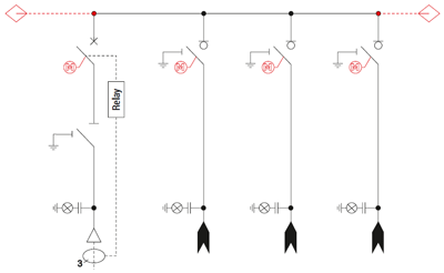
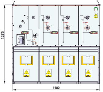
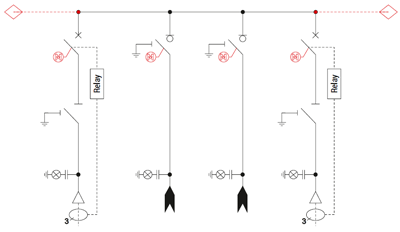
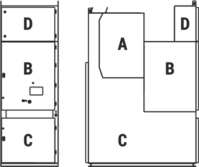
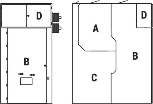
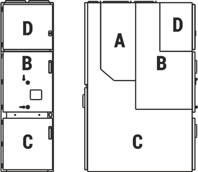
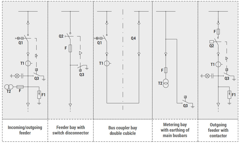
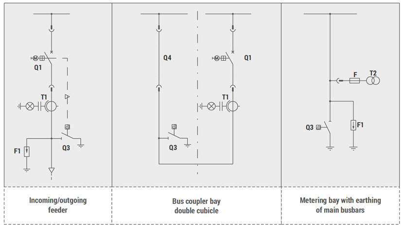
Types of bays of medium-voltage switchgears

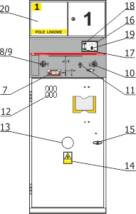
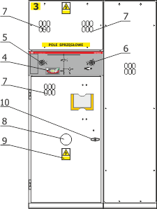
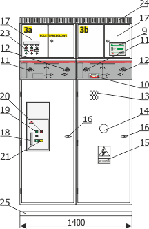
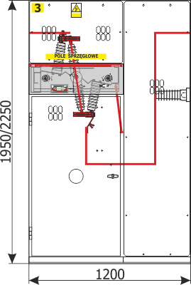
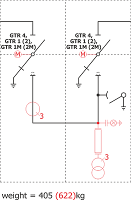
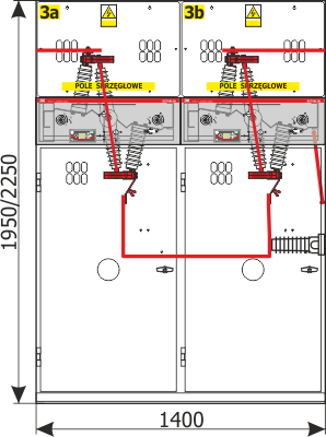
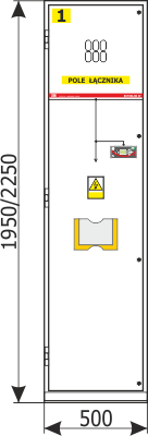
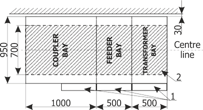
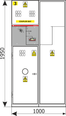
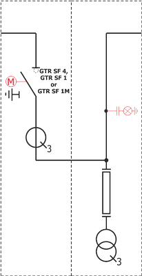
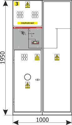
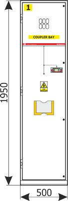
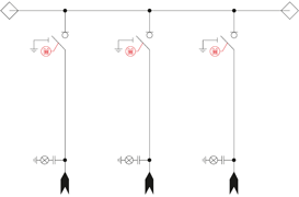
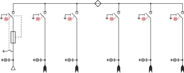
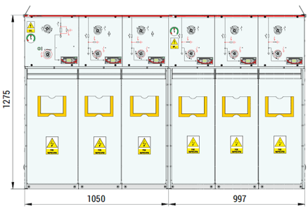
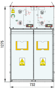
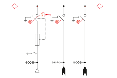
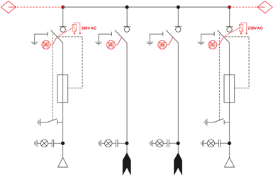
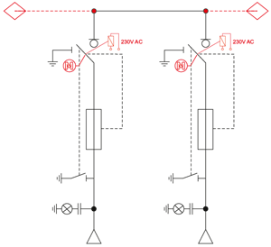
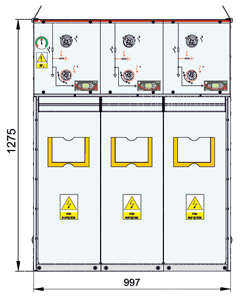
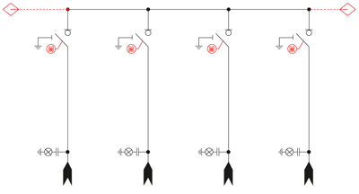
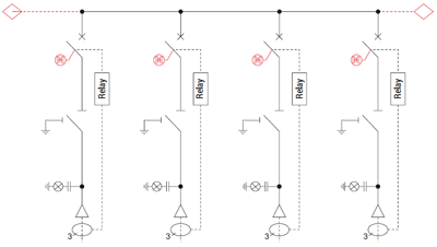
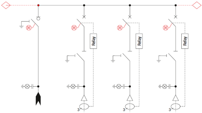
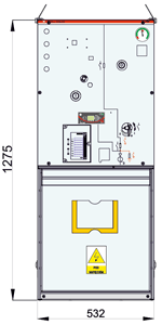
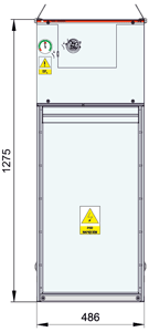
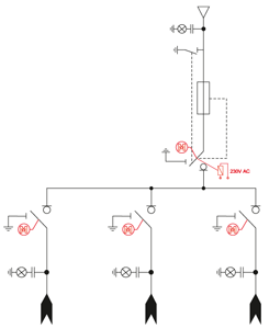
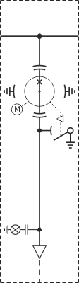
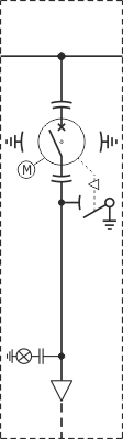
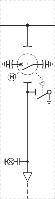
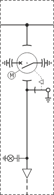
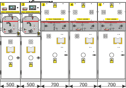
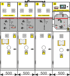
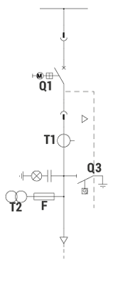
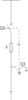
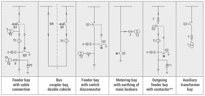
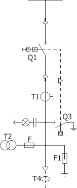
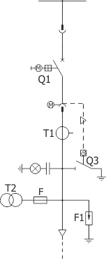
Medium-voltage switchgear consists of different types of bays (current paths designed to perform specific tasks). The distinctions include:

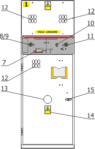
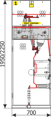
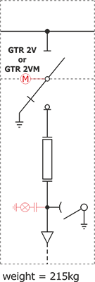
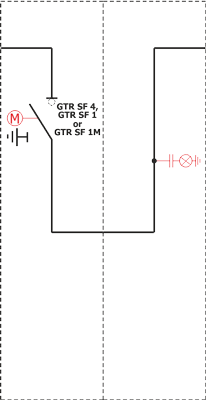
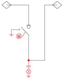
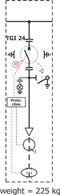
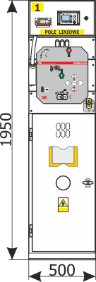
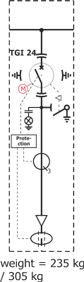
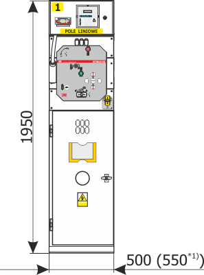
  • Line bays - connecting power lines to busbars,
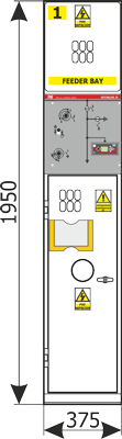
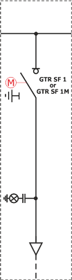
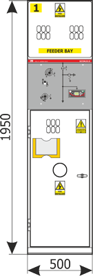
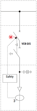
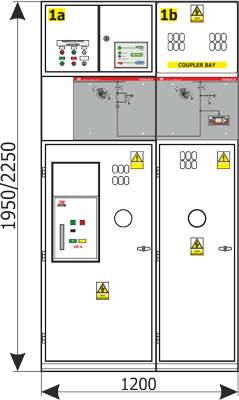
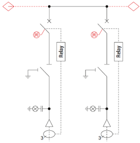
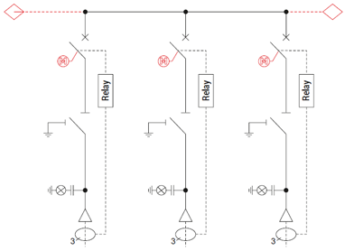
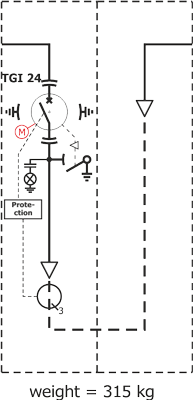
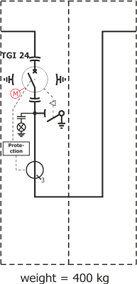
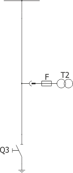
  • Breaker bays - connecting and protecting lines, networks, transformers, etc.
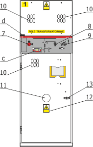
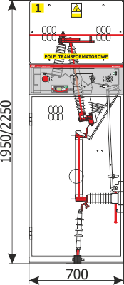
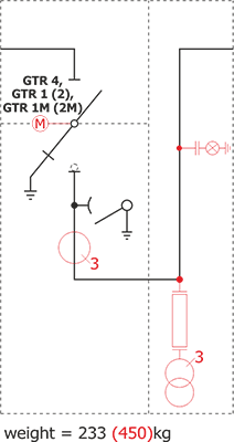
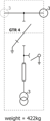
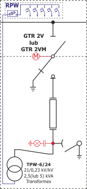
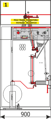
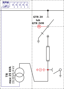
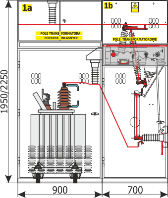
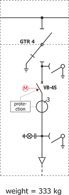
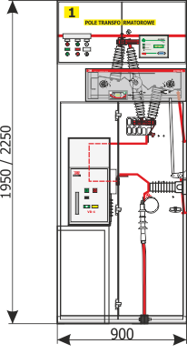
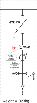
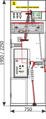
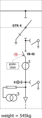
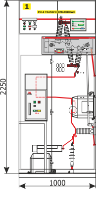
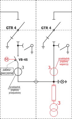
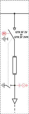
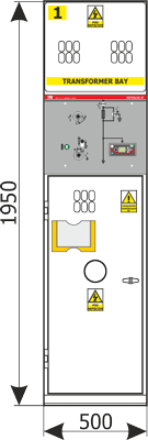
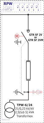
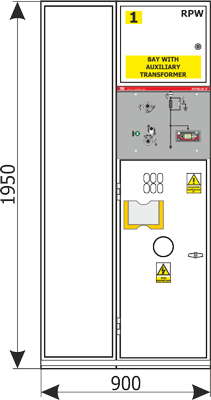
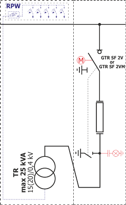
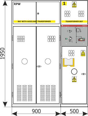
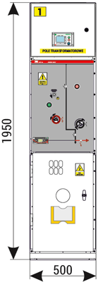
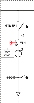
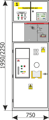
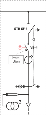
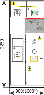
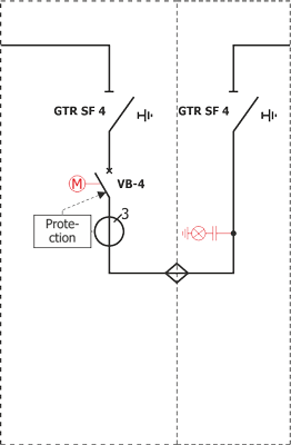
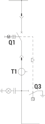
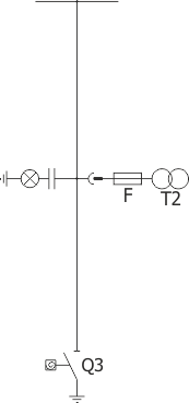
  • Transformer bays - connecting transformer windings to busbars,
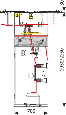
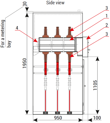
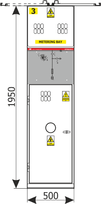
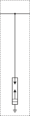
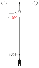
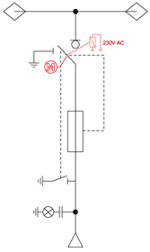
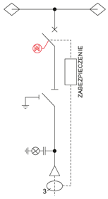
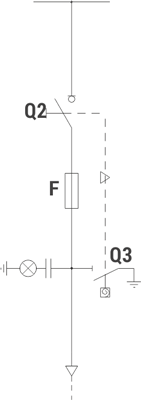
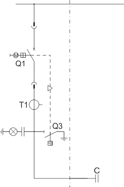
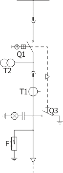
  • Measuring bays - containing a disconnector, protection, and voltage transformers (optionally, also current transformers),
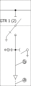
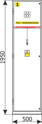
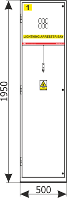
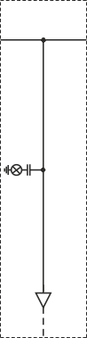
  • Lightning protection bays - used to protect against the effects of lightning.

Depending on the needs, the bays can be used in many different combinations.

Types of MV switchgear and examples

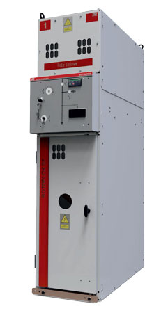
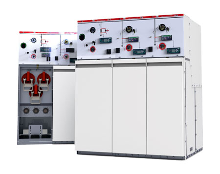
ZPUE offers a wide range of safe, reliable, and optimized switchgear. ZPUE medium-voltage switchgear can be used for primary and secondary power distribution and is made in different insulation, design, etc.

Energy distribution

Medium-voltage switchgear can be divided into the following categories by energy distribution:

  • Primary energy distribution,
  • Secondary energy distribution.

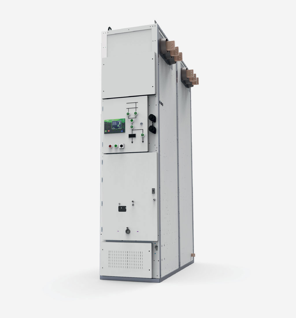
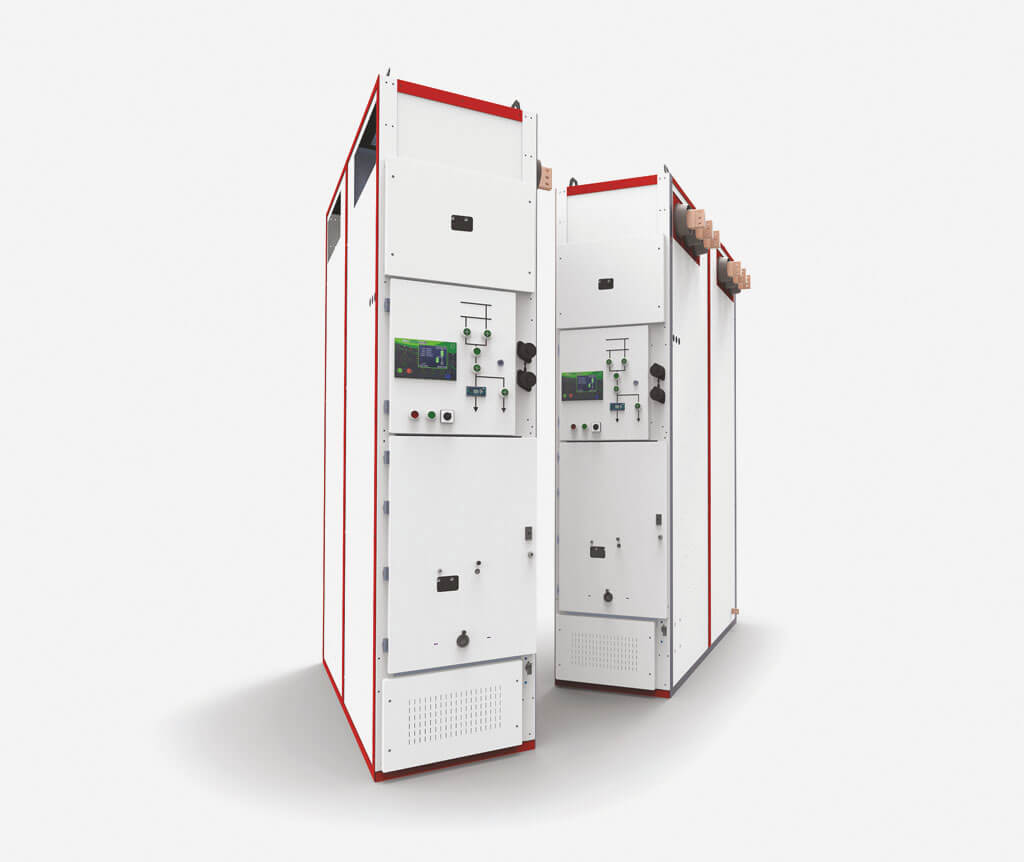
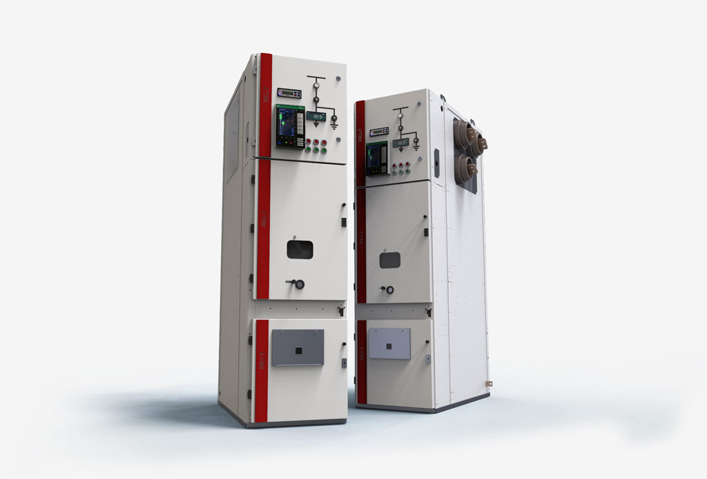
Primary power distribution switchgears are fed from the power system after the HV/SN transformer in GPZ stations. They find their application in electrical distribution stations that generate, transmit, and use electricity. Examples of such switchgear: RELF, RELF 2S, RXD.

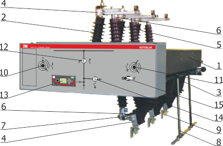
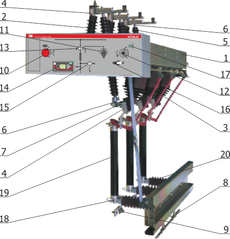
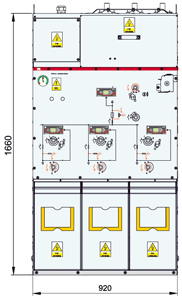
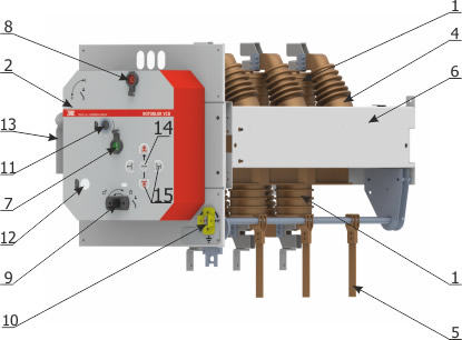
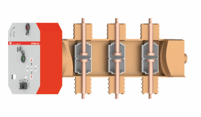
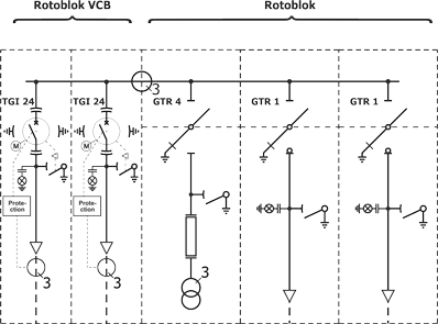
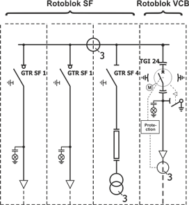
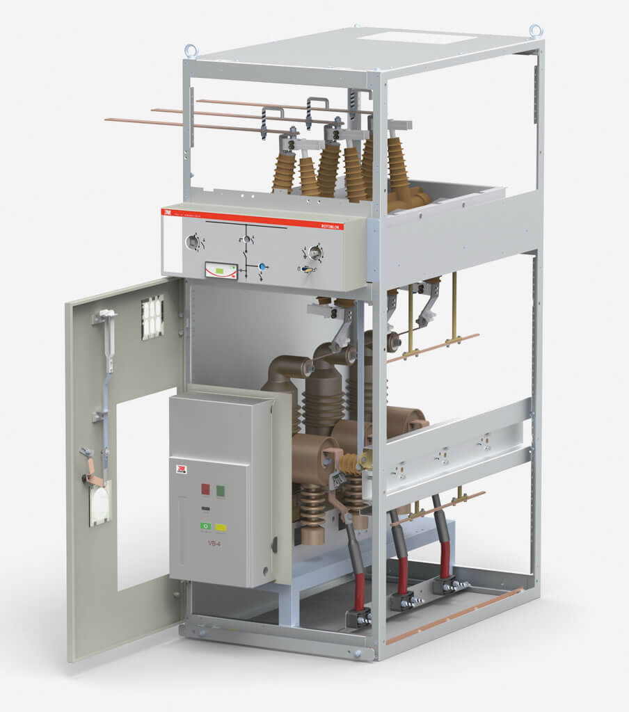
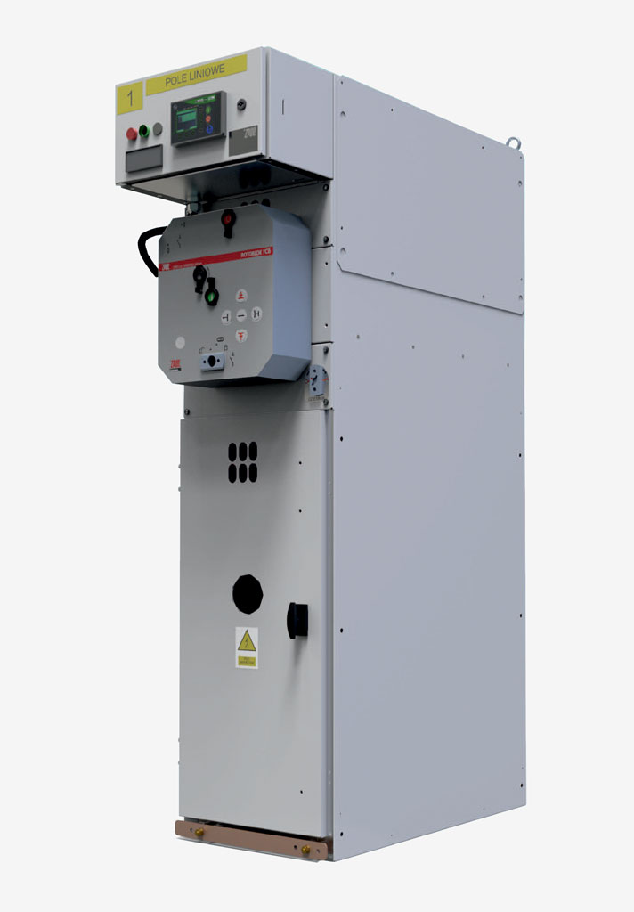
Secondary energy distribution switchgears are fed from primary distribution switchgears: from GPZs, they work in distribution networks. Examples include: TPM, Rotoblok, Rotoblok SF, Rotoblok VCB.

Type of insulation used

These are the following types of MV switchgear insulation:

  • Air, AIS (Air Insulated Switchgear),
  • Gas, GIS (Gas Insulated Switchgear).

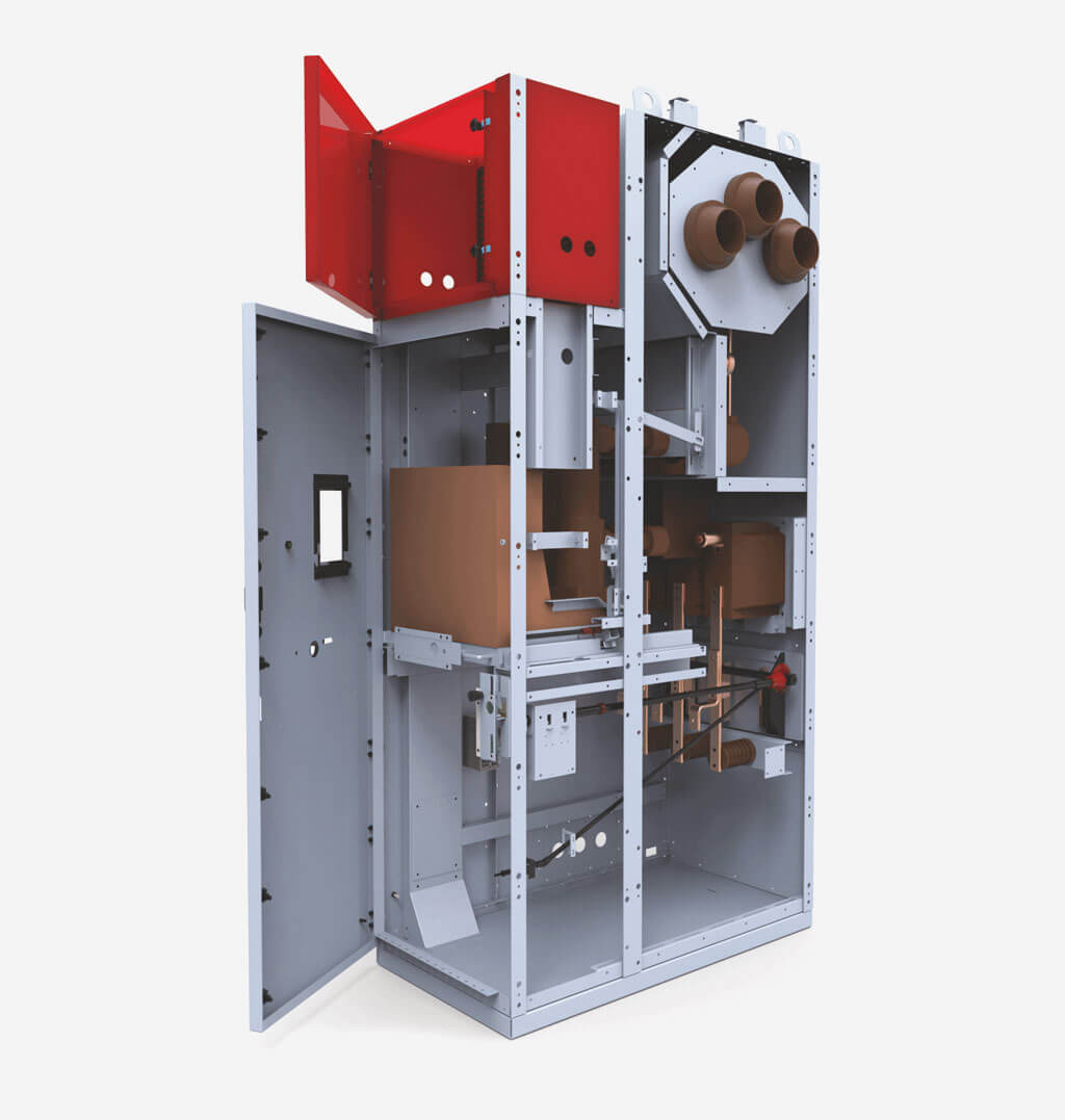
Air-insulated switchgears are those in which atmospheric air acts as insulation between live active components.

Gas-insulated switchgears are those in which this insulation is provided by an insulating gas other than atmospheric air.

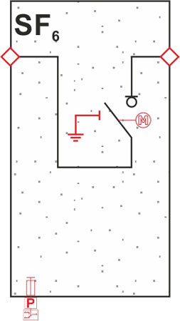
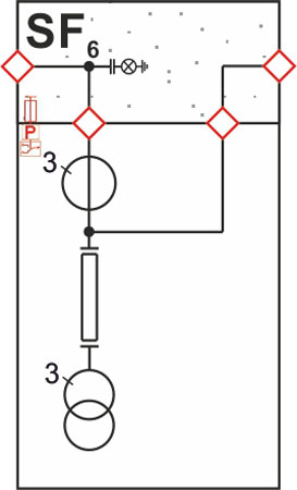
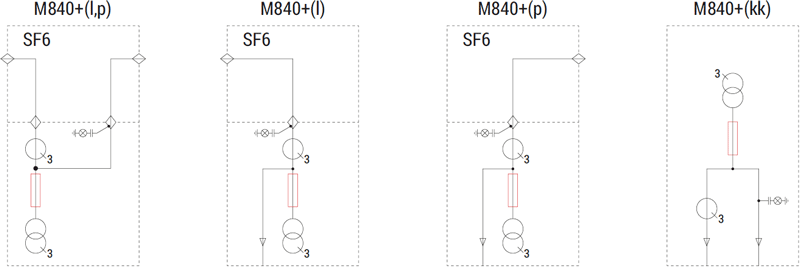
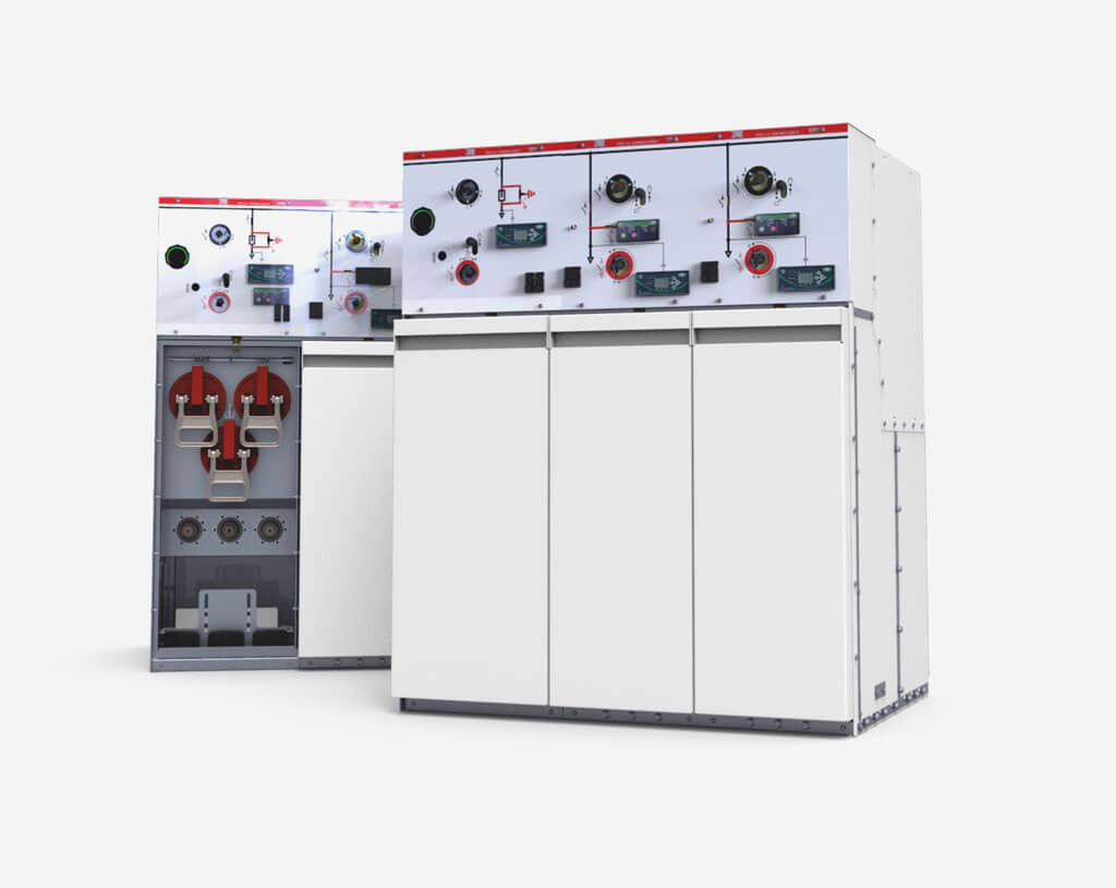
The most commonly used gas in gas-insulated switchgear is SF6 gas (sulfur hexafluoride). The very good insulating properties of sulfur hexafluoride compared to air mean that its use can reduce the area occupied by the switchgear by a factor of two.
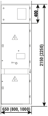
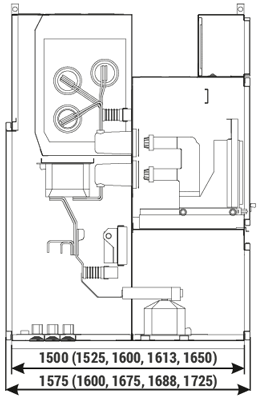
Construction

Taking into account their structure, MV switchgears can be divided into two categories:

  • Modular,
  • Compact.

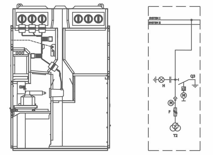
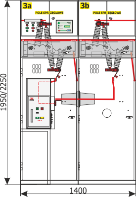
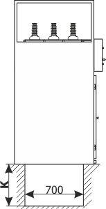
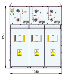
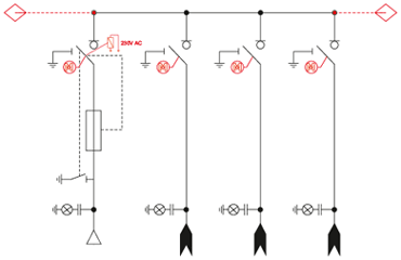
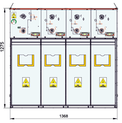
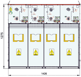
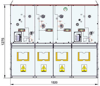
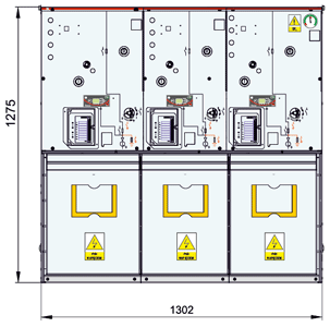
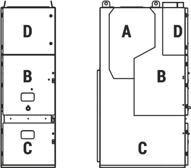
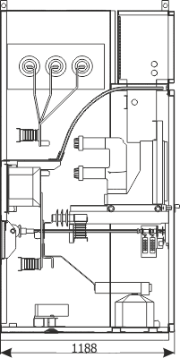
In modular switchgears, each functional bay (power supply, coupling, measurement, etc.) is located in a separate enclosure. These enclosures are juxtaposed with each other to form a sequence simply called switchgear. Examples of such switchboards are: RELF, RELF 2S, RXD, Rotoblok Group, TPM (expandable design).

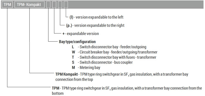
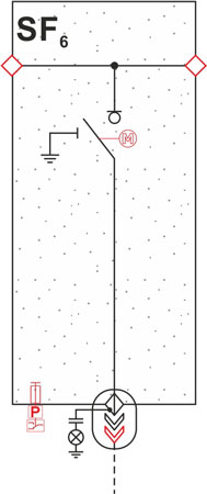
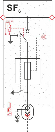
Compact switchgears are usually gas switchgears. Here, all functional bays and all apparatus of these bays are enclosed in a single housing. Most often, the housing of all switchgear connectors is a hermetic tank filled with insulating gas. These are usually ring switchgear - RMU (Ring Main Unit). Example: TPM.

Busbar system

In this category, we distinguish the following types of switchboards:

  • Single-system,
  • Dual-system.

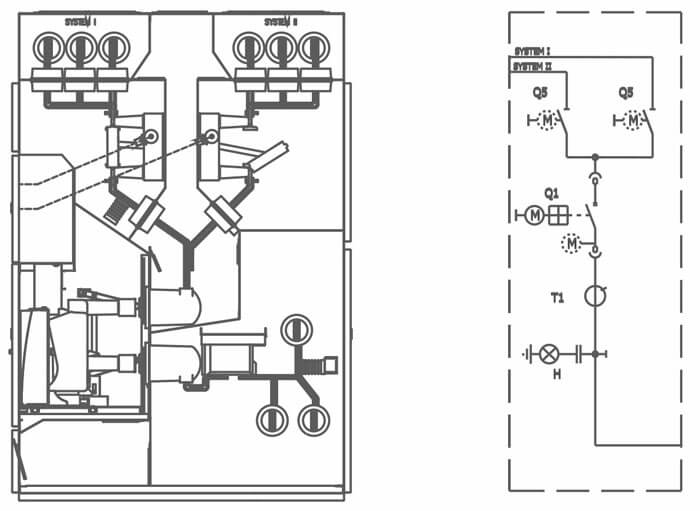
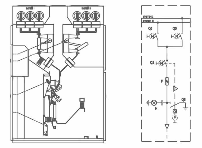
Single-system MV switchgears have a single busbar system. Examples of such switchgear: RELF, RXD, Grupa Rotoblok, TPM.

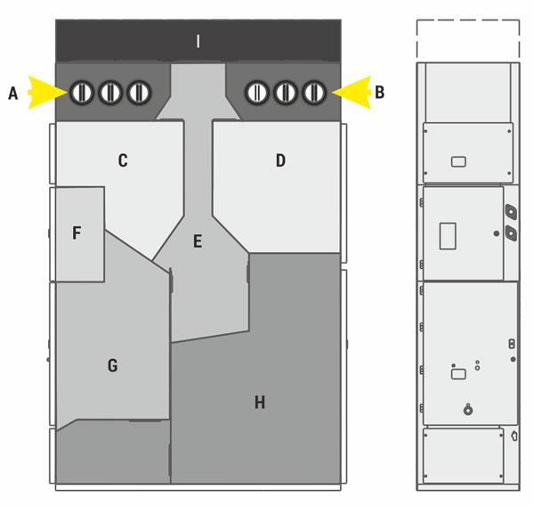
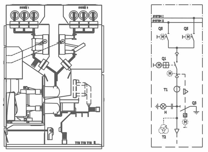
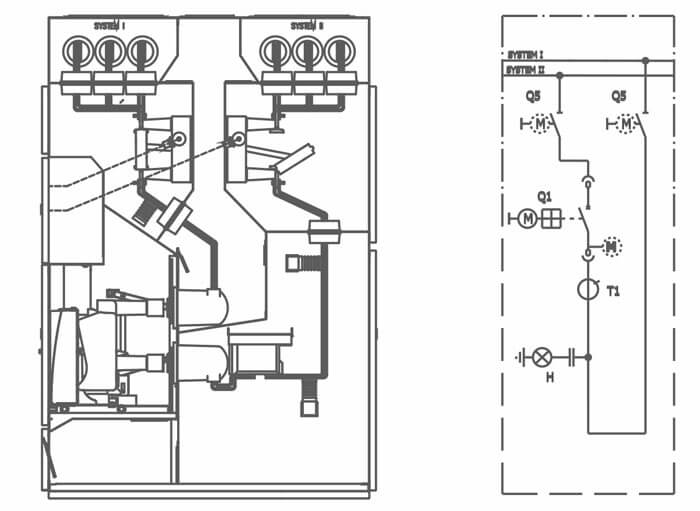
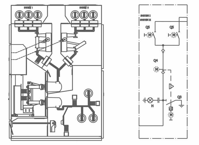
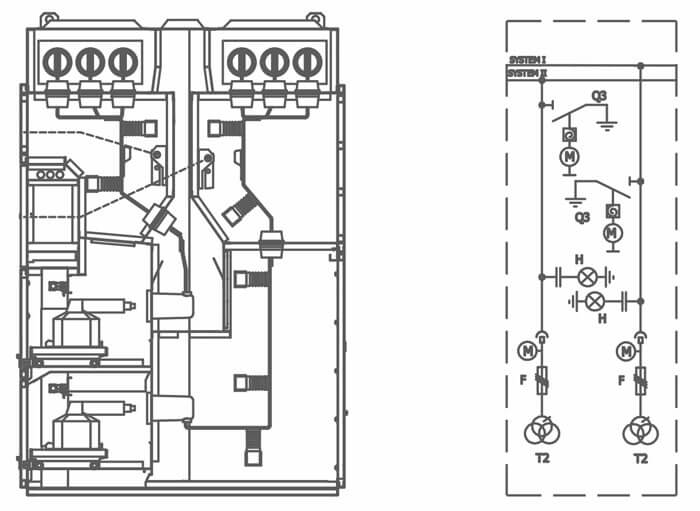
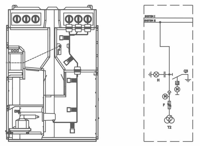
A dual-system switchgear, on the other hand, comes with a double busbar system. In ZPUE, this condition is met by the RELF 2S medium-voltage switchgear.

Distinguishing features of ZPUE switchgears

Common features of all our MV switchgears:

  • High operating safety,
  • High technical parameters,
  • Ability to operate in all MV network systems,
  • Flexibility: ability to be equipped with a wide range of apparatus,
  • Modular design that allows you to easily expand existing and design new sets,
  • Long service life compliance with IEC standards.

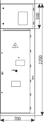
For the sake of operator safety and the possibility of long, trouble-free operation, MV switchgears are equipped with a system of interlocks and shock protection measures as standard. The durability of our switchgears is ensured by robust metal enclosures made in accordance with the requirements of the PN EN 62271-200 standard, whose expected service life under normal operating conditions, indoors, is at least 30 years. The safety of our products is confirmed by the type tests performed on independent accredited testing units.

It is worth noting that ZPUE S.A. provides comprehensive solutions, from switchgear design to manufacture. Each supplied switchgear is properly tailored to the customer's needs. This is what makes us stand out in the market. All switchgears produced by ZPUE S.A., thanks to well thought-out solutions, are adapted to cooperate with all available SCADA systems.

Rozdzielnica średniego napięcia Relf 2S

The page presents RELF 2S type medium voltage switchgear:

  • air insulated,
  • metal-clad,
  • withdrawable,
  • double busbar,
  • with rated voltage 12 kV,
  • for indoor use.

RELF 2S is a modular, withdrawable, metal-clad, air insulated switchgear for primary distribution. It was equipped with double busbar system, which enable the creation of state of the art, complex supplying systems in distribution stations for industry and for generation and distribution sector. The use of interlocks system and an arc-proof design ensures highest possible operational safety and switchgear maintenance. It is intended for operation in normal conditions, as specified by the (PN-EN) IEC 62271-1 standard.

Types of bays

The switchgear may be composed of various functional units:

  • feeder bays with a circuit breaker and with optional voltage measurement,
  • transverse bus coupler bay,
  • longitudinal, double cubicle bus coupler bay with a circuit breaker and sectionalizer,
  • metering bay,
  • feeder bay with switch disconnector.

The withdrawable module of the switchgear may be equipped with a circuit breaker, contactor, sectionalizer, set of fused voltage transformers. It may be placed in the positions of: service, test/disconnection and separation.

Characteristics and advantages

Main advantages

  • visual inspection of the state of switches - disconnectors, circuit breaker and earthing switch
  • doors in the rear of the switchgear - excellent access to cables and instrument transformers
  • removable inspection plates - easy access to disconnectors
  • advanced gas blow-out system - specially designed pressure relief duct discharges pressure from inside the bay
  • optional gas exhausting duct - discharges gases outside of the switching room
  • remote control - optional electrical drives for all switches
  • possibility of equipping with current and voltage sensors
  • bay with a fused switch disconnector - auxiliary transformer feeder

Characteristic features

  • air insulated,
  • frame-less, self-supporting design constructed with zinc-coated riveted steel sheets,
  • double busbar system,
  • IAC AFLR internal arc classification,
  • interlocks and protections against performing incorrect switching operations,
  • free-standing with access to cable connections from the rear of the cabinet,
  • ease of operation,
  • versions with manual drives or electrical drives of main switches and withdrawable module are available, depending on requirements and configuration of switchgear bays,
  • high operational safety.

The switchgear is designed in a manner that ensures that normal operation, inspections and maintenance operations may be performed in a safe manner.

High operational safety is achieved through:

  • internal arc resistance of the switchgear enclosure,
  • interlocks between switching operations and opening of doors,
  • racking the withdrawable module with doors closed,
  • controlling the switches remotely or locally,
  • the use of internal compartments and partitions,
  • the possibility of visual control of switching operations through inspection windows,
  • bay voltage indication system.

Basic technical data

Compliance with standards:

The RELF 2S type switchgear meets the requirements of the following standards:

  • (PN-EN) IEC 62271-1 - “High-voltage switchgear and controlgear. Common specifications”,
  • (PN-EN) IEC 62271-200 - “High-voltage switchgear and controlgear. AC metal-enclosed switchgear and controlgear for rated voltages above 1 kV and up to and including 52 kV”,

The switchgear is certified by appropriate accredited bodies.

Basic technical data
PARAMETERS   TYPE
RELF 2S
Rated voltage [kV] 12
Main busbars and incoming feeder
rated continuous current
[A] 630 1250 1600 2000 2500
Rated power-frequency withstand voltage [kV] 28
Rated lightning impulse withstand voltage [kV] 75
Rated frequency [Hz] 50
Rated short-time withstand current [kA/3s] 31,5
Rated peak withstand current [kA] 80
Withstand for internal arcing fault [kA/1s] 31,5
Degree of protection   up to IP4X
Cubicle width [mm] 650 8001) 800 (650) 800 1100 1100
Cubicle height [mm] 27002)
Cubicle depth [mm] 1800
Compliance with standards (PN-EN) IEC 62271-200; (PN-EN) IEC 62271-1; (PN-EN) IEC 60529
1) Width of bay with a switch disconnector
2) Height of the cubicle without the gas exhausting “I” (gas exhausting duct as optional equipment)

Design

The RELF 2S switchgear bay is designed as a cubicle with separate functional compartments:

RELF 2S switchgear bay is designed as a cubicle with separate functional compartments

Functional compartments of a feeder bay with circuit breaker:

  1. busbar compartment of system I
  2. busbar compartment of system II
  3. disconnector compartment of system I
  4. disconnector compartment of system II
  5. internal pressure relief and blow-out duct
  6. auxiliary circuits LV compartment
  7. main device compartment
  8. cable compartment
  9. gas exhausting duct (optional)

Feeder bay with a circuit breaker (option with voltage measurement)

Feeder bay with a circuit breaker (option with voltage measurement)

Longitudinal bus coupler bay with circuit breaker

Longitudinal bus coupler bay with circuit breaker

Transverse bus coupler bay

Transverse bus coupler bay

Longitudinal coupler bay with sectionalizer

Longitudinal coupler bay with sectionalizer

Metering bay – SYSTEM I and II

Metering bay – SYSTEM I and II

Metering bay – SYSTEM II

Metering bay – SYSTEM II

Metering bay – SYSTEM I

Metering bay – SYSTEM I

Bay with switch disconnector

Bay with switch disconnector

Designations of devices used in the switchgear bays
Q1 circuit breaker
Q2 switch disconnector
Q3 earthing switch
Q4 sectionalizer
Q5 disconnector
F fuse link
T1 current transformer
T2 voltage transformer
H voltage indicator

Other types of bays on arrangement with the manufacturer.
Bay equipment may be adapted to special requirements on arrangement with the manufacturer.

Rozdzielnica Rotoblok

The subject of this document is a ROTOBLOK type state-of-the-art, indoor medium voltage switchgear intended for distribution of three-phase alternating current with a frequency of 50 Hz, at a rated voltage up to 24 kV, in industrial and commercial power sector distribution grids. The switchgears are configured from standard single bays with varied equipment. The information and technical data specified herein enable the designer to assemble a switchgear from typical modules. In case bays with equipment not specified herein or with changed dimensions are needed, the scope of equipment should be arranged with the manufacturer.

Characteristics

The Rotoblok type switchgear is a two compartment, indoors switchgear in metal enclosure made of zinc-coated metal sheet (which ensures equipotential bonding), with a single primary busbars system. The switchgear is equipped with state-of-the-art, air insulated switching devices. It has separate primary busbars and cable compartments, and the arc-proof design ensures high level of operational safety.

The distribution bays have the following properties:

  • small external dimensions compared to rated voltage, defined insulation levels, primary busbar rated currents and short-circuit currents,
  • two-compartment bay ensuring the separation of the primary busbar circuit from the section used to connect power supply cables,
  • high reliability of operation,
  • long operating period without the need for troublesome maintenance operations,
  • high corrosion resistance, the switchgear design uses metal sheet which has been zinc-coated for corrosion protection,
  • universality in designing different switchgear configurations with any number of bays,
  • use of state of the art, reliable switching devices, such as GTR type disconnectors and switch disconnectors (ZPUE), or circuit breakers by other manufacturers,
  • adapted for the installation of state of the art protection and control devices,
  • the possibility of wall-mounting of the switchgear, saving space in the switching room, which is particularly important during retrofits and expansions of existing switching stations,
  • easy and quick access to switchgear devices for supervision and maintenance,
  • simple operation.

System of interlocks and protections

A system of interlocks prevents incorrect switching operations and opening of the distribution bay doors before voltage is disconnected and the earthing switch is closed. Opening of the earthing switch is possible only when the bay doors are closed (or after the interlock is purposefully released with a special key provided with the switchgear - for example in order to perform a voltage test of a cable). Each feeder bay and circuit breaker bay is equipped as standard with capacitive voltage dividers on each phase and a voltage indicator. Such a solution facilitates checking the cable for lack of voltage and safe phase testing with a phase comparator.

At the customer's request it is possible to provide capacitive voltage dividers in bays which do not have them as standard.

High safety of operation, achieved by:

  • arc-proof design - resistance to internal arcing effects,
  • specially reinforced bay design (enclosures, locks, hinges),
  • mechanical interlocks, which prevent incorrect switching operations and touching live devices,
  • access to controlgear and control circuits is possible while the primary circuits parts cannot be touched by the operator,
  • the use of monitoring and signalling systems, and mechanical and electrical position indicators, and inspection windows,
  • visual indicator of disconnector contacts, switch-disconnector and earthing switch state, and installing of inspection windows to control them,
  • possibility of disconnecting the switch disconnector without an operating lever (optional - GTR 2, GTR 2V),
  • the use of visible double gap disconnectors and switch disconnectors,
  • forcing the sequence of switching operations.

Basic technical data

Compliance with standards:

The Rotoblok type switchgear meets the requirements of the following standards:

  • PN-EN62271-1 - “High-voltage switchgear and controlgear. Common specifications”,
  • PN-EN 62271-200 - “High-voltage switchgear and controlgear. AC metal-enclosed switchgear and controlgear for rated voltages above 1 kV and up to and including 52 kV”,
  • PN-EN 62271-100 - “High-voltage switchgear and controlgear. Alternating-current circuit-breakers”,
  • PN-EN 62271-102 - “High-voltage switchgear and controlgear. Alternating current disconnectors and earthing switches”,
  • PN-EN 62271-103 - “High-voltage switchgear and controlgear. Switches for rated voltages above 1 kV up to and including 52 kV”,
  • PN-EN 62271-105 - “High-voltage switchgear and controlgear. Alternating current switch-fuse combinations”.

The switchgear is certified by the Electrotechnical Institute.

Electrical data:
  Rotoblok 17,5kV Rotoblok 24
Rated network voltage 15 kV 20 kV
Highest device voltage 17,5 kV 24 kV
Rated frequency / number of phases 50 Hz / 3
Rated short-time network frequency
withstand voltage
55 kV / 63 kV 50 kV / 60 kV
Rated withstand lightning surge voltage 1,2/50 μs 95 kV / 110 kV 125 kV / 145 kV
Continuous rated current 630 A / 1250 A 630 A - 1250 A
Rated short-time withstand current 16 kA (1s) 16 kA (1s)
Rated peak withstand current 40 kA 40 kA
IAC internal arc resistance classification AF up to 16 kA (1s)
IP protection rating IP4X
Service conditions:
Ambient temperature
- peak short-time
+ 40°C
- highest day average
+ 35°C
- highest annual average
+ 20°C
- lowest long-term
- 25°C1)
Relative humidity of air
- highest day average
95%
- highest month average
90%
- highest day average vapour pressure
2,2 kPa
- highest month average vapour pressure
1,8 kPa
Atmosphere at the place of installation no significant contamination with salt, vapour,
dust, smoke, flammable or corrosive gasses and
lack of icing, frosting and dewing
Installation altitude up to 1000 m asl2)
Vibrations vibrations caused by external factors
or earthquakes negligible

Note:
*1) Unless the manufacturer of instrumentation & control and protection devices has specified otherwise.
*2) If the switchgear installation altitude is higher than 1000 m ASL should corrected by an indicator in accordance with the guidelines of item 2.2.1 of the PN-EN 62271-1 standard.

Rated power of transformers that can be connected and disconnected using GTR 2V disconnectors, depending on voltages on the MV side:
Rated network voltage Rated current Max. transformer power
6 kV 60,6 A 630 kVA
10 kV 57,7 A 1000 kVA
15 kV 48,1 A 1250 kVA
20 kV 46,2 A 1600 kVA

In case of transformers with higher powers please contact the switchgear manufacturer.
In Rotoblok type switchgear typical fuse links are used acc. to the IEC 282-1, DIN 43625 standard, with thermal protection.

Construction of switchgear type Rotoblok

The design of each bay includes elements constructed with zinc-coated metal sheet, and bolted or riveted together. The construction of each bay ensures the possibility of easy assembly in any switchgear unit, and also rapid disassembly (e.g. in order to carry single bays into the station) and custom reconfiguration. Each bay may be constructed wider than its standard dimension. This solution is used when replacing older large size switchgears (e.g. Rue, M20) with a Rotoblok switchgear, when problems may occur with shifting the old cables to a new attachment point.

Each bay has two compartments, that is, the frame and the main disconnector shaft form a mechanical and electrical partition between the lower part of the switchgear and the primary busbar circuit. After opening the bay doors touching the primary busbar circuit is impossible. Each bay is equipped with a lower earthing switch (in a transformer bay it is installed under the fuse bases).

Each bay has a system of mechanical interlocks, which fulfils two primary tasks:

  • prevents opening the door of any compartment before its power supply is switched off and the earthing switch is closed; therefore it prevents electric shock,
  • forces the proper sequence of the switching operations.

Capacitive voltage dividers used in the bays allow checking for lack of voltage, and safe phase testing from the front side of the bay, in a safe manner, using a LV bipolar indicator without needing to open the bay doors. Additionally, inspection windows installed in the doors allow the observation of each element in the bay, for example: open circuits, condition of transformers, chambers, connections, etc.

An auxiliary circuits compartment is located at the top of the circuit breaker bay, used to install such elements as: terminal strips, relays, batteries, additional (or primary) protection modules, etc.

Switching devices

The main devices used in the aforementioned bays include:

  • GTR1, GTR 2, GTR 2V type switch disconnectors (ZPUE)
  • GTR 4, GTR 4W type disconnectors (ZPUE)
  • circuit breakers by leading manufacturers
View of the GTR 1 switch disconnector in the “on” position
Rotoblok - Widok rozłącznika GTR 1 w pozycji „załącz”

1 - galvanized steel frame
2,3 - resin insulators
4 - fixed contacts
5 - primary isolating shaft
6 - mobile contacts
7 - arc-quenching contact
8 - lower grounding switch
9 - grounding switch contact
10 - switch disconnector socket
11 - grounding switch socket
12 - switch disconnector position indicator
13 - voltage indicator
14 - grounding switch position indicator
15 - door interlock leaver

View of the GTR 2V switch disconnector in the “on” position
Rotoblok - Widok rozłącznika GTR 2V w pozycji “załącz”

1 - zinc-coated steel frame
2,3 - resin insulators
4 - fixed contacts
5 - main insulating shaft
6 - moving contacts
7 - arcing moving contact
8 - lower earthing switch
9 - earthing switch contact
10 - charging socket and charging indicator
11 - “on”/“off” switch
12 - earthing switch socket
13 - switch disconnector position indicator
14 - voltage indicator
15 - earthing switch position indicator
16 - door interlock lever
17 - fuse link position indicator
18 - fuse base
19 - fuse link
20 - post insulator or capacitive voltage divider

Line feederwith manual drive

Electrical diagram
Electrical diagram Rotoblok - Feeder bay with manual drive
Front view
Front view Rotoblok - Feeder bay with manual drive
Inside front view
Inside front view Rotoblok - Feeder bay with manual drive
Inside side view
Inside side view Rotoblok - Feeder bay with manual drive
* Rotoblok 17,5 kV switchgear depth
 
Standard equipment
  Device name Type Amount
1. Switch disconnector with a lower earthing switch GTR 1 or GTR 2 1
2. Busbar circuit P 40x5 / P 40x10 3
3. Capacitive voltage divider   3
4. Cable clamp UKZ 3
5. Cable termination   3
6. Cable   3
7. Neon voltage indicator operating with the capacitive voltage divider   1
8. Switch disconnector socket (for GTR 1)   1
9. Charging socket and indicator (for GTR 2)   1
10. “On”/“off” switch (for GTR 2)   1
11. Earthing switch socket   1
12. Inspection window   1
13. Window which allows the use of a
torch to check the position of
contacts in case of a lighting failure
  3
14. Warning plate   1
15. Door handle   1
 
Additional equipment at the customer's request
a Short-circuit current indicator attached by cable 1
b Short-circuit current indicator attached by busbar 3

Line feeder with motor drive

Electrical diagram
Electrical diagram Rotoblok - Feeder bay with motor drive
Front view
Front view Rotoblok - Feeder bay with motor drive
Inside front view
Inside front view Rotoblok - Feeder bay with motor drive
Inside side view
Inside side view Rotoblok - Feeder bay with motor drive
* Rotoblok 17,5 kV switchgear depth
Standard equipment
  Device name Type Amount
1. Switch disconnector with a lower earthing switch and motor drive adapted for remote control via cables or via radio GTR 1M or GTR 2M 1
2. Busbar circuit P 40x5 / P 40x10 3
3. Capacitive voltage divider   3
4. Cable clamp UKZ 3
5. Cable termination   3
6. Cable   3
7. Neon voltage indicator operating with the capacitive voltage divider   1
8. Switch disconnector socket (for GTR 1M)   1
9. Charging socket and indicator (for GTR 2M)   1
10. “On”/“off” switch (for GTR 2M)   1
11. Earthing switch socket   1
12. Inspection window   1
13. Window which allows the use of a torch to check the position of contacts in case of a lighting failure   3
14. Warning plate   1
15. Door handle   1
16. Control panel for motor drive   1
17. “Close” button   1
18. “Open” button   1
19. Operation mode selection switch   1
20. Auxiliary circuits compartment   1
Additional equipment at the customer's request
a Short-circuit current indicator attached by cable 1
b Short-circuit current indicator attached by busbar 3

Transformer feeder design

Electrical diagram
Electrical diagram Rotoblok - Transformer bay design
Front view
Front view Rotoblok - Transformer bay design
Inside front view
Inside front view Rotoblok - Transformer bay design
Inside side view
Inside side view Rotoblok - Transformer bay design
* Rotoblok 17,5 kV switchgear depth
Standard equipment
  Device name Type Amount
1. Fuse switch disconnector with earthing switch GTR 2V 1
2. Busbar circuit P 40x5 / P 40x10 3
3. Post insulator   3
4. Cable clamp UKZ 3
5. Cable termination   3
6. Cable   3
7. Charging socket and indicator   1
8. “On”/“off” switch   1
9. Earthing switch socket   1
10. Inspection window   1
11. Window which allows the use of a torch to check the position of contacts in case of a lighting failure   3
12. Warning plate   1
13. Door handle   1
14. Fuse base which forms an integral part of the switch disconnector   1
15. Fuse link   1
Additional equipment at the customer's request
a Fuse switch disconnector with earthing switch and motor drive GTR 2VM 1
b Capacitive voltage divider   3
c Neon voltage indicator operating with the capacitive voltage divider   1
d Tripping coil   1
e Gland for cable entry with the use of a tripping coil   1
Note!
The earthing switch in the switch disconnector earths the lower part of the fuse link.

Tripping coil operation in a transformer bay with gas-flow protection or thermal protection of the transformer

Rotoblok - Tripping coil operation in a transformer bay with gas-flow protection or thermal protection of the transformer

Note!
Cable cross-section and protection currents should be selected according to the tripping coil supply voltage.

Bus coupler unit design

Electrical diagram
Electrical diagram Rotoblok - Bus coupler bay design
Front view
Front view Rotoblok - Bus coupler bay design
Inside front view
Inside front view Rotoblok - Bus coupler bay design
Inside side view

Inside side view Rotoblok - Bus coupler bay design

* Rotoblok 17,5 kV switchgear depth
Standard equipment
  Device name Type Amount
1. Disconnector with a lower earthing switch GTR 4 1
2. Busbar circuit P 40x5 / P 40x10 3
3. Post insulator or capacitive voltage divider   3
4. Neon voltage indicator operating with the capacitive voltage divider   1
5. Disconnector socket   1
6. Earthing switch socket   1
7. Inspection window   1
8. Window which allows the use of a torch to check the position of contacts in case of a lighting failure   3
9. Warning plate   1
10. Door handle   1
Additional equipment at the customer's request
a Switch disconnector with a lower earthing switch GTR 2 1
b Switch disconnector with a lower earthing switch and motor drive GTR 1M or GTR 2M 1
Note!
The construction of a bus coupler bay without a lower earthing switch is possible

Desing of transformer feeder type RWT

Electrical diagram
Electrical diagram Rotoblok - RWT type bay design
Front view
Front view Rotoblok - RWT type bay design
Inside front view
Inside front view Rotoblok - RWT type bay design
Inside side view
Inside side view Rotoblok - RWT type bay design
Standard equipment
  Device name Type Amount
1. Circuit breaker   1
2. Disconnector with a lower earthing switch GTR 4 1
3. Busbar circuit P 40x5 / P 40x10 3
4. Capacitive voltage divider   3
5. Cable clamp UKZ 3
6. Cable termination   3
7. Cable   3
8. Current transformer operating with the protection system IP 24 / PP-20W / PP-15W 3
9. Protection system Mupasz / REF MiCOM 1
10. Neon voltage indicator operating with the capacitive voltage divider   1
11. Disconnector socket   1
12. Earthing switch socket   1
13. Inspection window   1
14. Window which allows the use of a torch to check the position of contacts in case of a lighting failure   1
15. Warning plate   1
16. Door handle   1
17. Auxiliary circuits compartment   1
18. Charging socket   1
19. “ON” button   1
20. “OFF” button   1
21. Charging indication   1
23. Control switches and lamps   1
24. Cable tray   1
25. Load-bearing frame   1

Desing of bus cupler unit type RWS

Electrical diagram
Electrical diagram Rotoblok - RWS type bay design
Front view
Front view Rotoblok - RWS type bay design
Inside front view
Inside front view Rotoblok - RWS type bay design
Inside side view
Inside side view Rotoblok - RWS type bay design
Standard equipment
  Unit Type Amount
1. Circuit breaker   1
2. Disconnector with a lower earthing switch GTR 4 1
3. Busbar circuit P 40x5 / P 40x10 3
4. Capacitive voltage divider   3
8. Current transformer operating with the protection system IP 24 / PP-20W / PP-15W 3
9. Protection system Mupasz / REF MiCOM 1
10. Neon voltage indicator operating with the capacitive voltage divider   1
11. Disconnector socket   1
12. Earthing switch socket   1
13. Inspection window   1
14. Window which allows the use of a torch to check the position of contacts in case of a lighting failure   1
15. Warning plate   1
16. Door handle   1
17. Auxiliary circuits compartment   1
18. Charging socket   1
19. „ON” button   1
20. „OFF” button   1
21. Charging indication   1
23. Control switches and lamps   1
24. Cable tray   1
25. Load-bearing frame   1
26. Insulating bushing   1

Control circuits panel: “auxiliary circuits compartment”

The auxiliary circuits compartment (17) contains control strips, protection units, control & metering devices and buttons. Based on documentation provided by the customer, the manufacturer determines the position of the auxiliary circuit devices in the switchgear. Auxiliary circuit leads and cables are placed in the compartment in cable trays, and exit the compartment through glands. The auxiliary circuits in the remaining compartments run in protection tubes. The bypass circuits between adjacent bays run in trays. It is recommended that auxiliary circuit cables are run from individual distribution bays to the control room in a cable duct or on cable ladders installed on the walls.

Construction method for a cable duct under the Rotoblok type MV switchgears

Figures 1, 2, 3 present a cable duct construction proposal. The cable bending radius (which depends on its outside diameter, according to PBUE) should taken into account when establishing the dry and oil cables duct depth. It is possible to avoid or reduce the depth of the cable duct by using a raised base or a raised floor.

Fig. 1 Top view - version with a common duct along the Rotoblok switchgear
Top view - version with a common duct along the Rotoblok switchgear


Note!: Minimum distance from the wall 30 mm
1) Example bays with a width of 700, 700, 900 mm (respectively, from the left)
2) Duct under the switchgear.

Fig. 2 Top view - version with separate outgoing feeders and cable entries at the rear of the Rotoblok switchgear
Top view - version with separate outgoing feeders and cable entries at the rear of the Rotoblok switchgear

* - Rotoblok 17,5 kV switchgear depth

Note!: Minimum distance from the wall 30 mm
1) Example bays with a width of 1000, 900 mm (respectively, from the left)
2) Duct under the switchgear.

Fig. 3 Side view
Rotoblok - Widok z boku
Dry single-core cable
Cable cross-section (mm2) Bending radius (mm) Duct depth K (mm)
50 370 400
70 400 430
95 440 470
120 470 500
150 500 550
185 540 600
240 590 700

Rotoblok switchgear cable connections

Switch disconnector and circuit breaker feeder bays
Cable type Cable termination
Manufacturer Type Cable cross-section [mm2]


Single core, with plastic insulation
e.g. YHAKXs, YHKX, XUHAKXs,
XRUHKs, ...
CELLPACK CHE-I 24kV 25-150
70-240
CAE-I 24kV 35-120
70-240
CAESK-I 24kV 70-150
120-240
Nexans (EUROMOLD) ITK224 (stretch sleeve) 25-240
AIP20 (slip-on) 25-120
AIS20 (slip-on) 70-300
AIN20 (slip-on) 25-1200
24MONOi1 (shrink sleeve) 25-240
TYCO ELECTRONIC Rated voltage Typ (stretch sleeve)  
6/10 POLT-12xxx 25-1200
8,7/15 i 12/20 POLT-24xxx 25-800
18/30 POLT-42xxx 35-800

*) Note: The manufacturer should be consulted regarding the manner of connection of cables and used terminations

Transformer bays
Single core, with plastic insulation e.g.
YHAKXs, YHKX, XUHAKXs,
XRUHKs, ...
As in feeder bays
Tri-core oil-filled with paper insulation
saturated with non-running saturant
and common coating, e.g.: HAKnFta,
KnY, KnFTA, ...
The manufacturer should be consulted
regarding the manner of connection of cables and used terminations

Note:
In all cases a cable duct is required under the switchgears. As an option, the switchgear may be placed on a raised base or on a raised floor. In case other type of terminations is used, please contact the manufacturer.

Various types of Rotoblok switchgear units

Side view of a circuit breaker or switch disconnector bay
Rotoblok - Side view of a circuit breaker or switch disconnector bay
Side view of an MV circuit breaker bay
Rotoblok - Side view of an MV circuit breaker bay
Side view of a switchgear with a busbar bridge combining two sections placed on opposite sides of a corridor - example solution
Rotoblok - Side view of a switchgear with a busbar bridge combining two sections placed on opposite sides of a corridor - example solution

* - Rotoblok switchgear 17,5 kV depth

Note:
Figures shown on subsequent pages are only an example of bay equipment. It is possible to adapt the bay configuration to specific requirements of the end user. In this case manufacturer should be asked to provide drawings.

RL1 (line feeder)

Electrical diagram
Electrical diagram Rotoblok - feeder bay
Cross-section Front view
Cross-section Front view Rotoblok - feeder bay

Note:
Optional equipment was marked with red on the electrical diagram.
1) It is possible to design the unit in mirrored version
2) It is possible to design the bus coupler unit without a lower earthing switch

RL4 (line feeder with metering)

Electrical diagram
Electrical diagram Rotoblok - feeder bay with metering
Cross-section Front view
Cross-section Front view Rotoblok - feeder bay with metering

Note:
Optional equipment was marked with red on the electrical diagram.
1) It is possible to design the unit in mirrored version
2) It is possible to design the bus coupler unit without a lower earthing switch

RT1 (transformer feeder)

Electrical diagram
Electrical diagram Rotoblok - transformer bay
Cross-section Front view
Cross-section Front view Rotoblok - transformer bay

Note:
Optional equipment was marked with red on the electrical diagram.
1) It is possible to design the unit in mirrored version
2) It is possible to design the bus coupler unit without a lower earthing switch

RS1L1) (bus coupler unit with disconnector or switch disconnector on the left side)

Electrical diagram
Electrical diagram Rotoblok - bus coupler bay with disconnector or switch disconnector on the left side
Cross-section Front view
Cross-section Front view Rotoblok - bus coupler bay with disconnector or switch disconnector on the left side

Note:
Optional equipment was marked with red on the electrical diagram.
1) It is possible to design the unit in mirrored version
2) It is possible to design the bus coupler unit without a lower earthing switch

RS4 (bus coupler unit with disconnector or switch disconnector on the left side)

Electrical diagram
Electrical diagram Rotoblok - bus coupler bay with disconnector or switch disconnector on the left side
Cross-section Front view
Cross-section Front view Rotoblok - bus coupler bay with disconnector or switch disconnector on the left side

Note:
Optional equipment was marked with red on the electrical diagram.
1) It is possible to design the unit in mirrored version
2) It is possible to design the bus coupler unit without a lower earthing switch

RP1 (metering unit)

Electrical diagram
Electrical diagram Rotoblok - metering bay
Cross-section Front view
Cross-section Front view Rotoblok - metering bay

Note:
Optional equipment was marked with red on the electrical diagram.
1) It is possible to design the unit in mirrored version
2) It is possible to design the bus coupler unit without a lower earthing switch

RO1 (lightning arrester unit)

Electrical diagram
Electrical diagram Rotoblok - lightning arrester bay
Cross-section Front view
Cross-section Front view Rotoblok - lightning arrester bay

Note:
Optional equipment was marked with red on the electrical diagram.
1) It is possible to design the unit in mirrored version
2) It is possible to design the bus coupler unit without a lower earthing switch

RŁ2 (Incoming cable-connection feeder)

Electrical diagram
Electrical diagram Rotoblok - switch bay
Cross-section Front view
Cross-section Front view Rotoblok - switch bay

Note:
Optional equipment was marked with red on the electrical diagram

Rtpwł4 (auxiliary transformer unit)

Electrical diagram
Electrical diagram Rotoblok - auxiliary transformer bay
Cross-section Front view
Cross-section Front view Rotoblok - auxiliary transformer bay

Note:
Optional equipment was marked with red on the electrical diagram

RTpwł 25kVA + RT1 (auxiliary transformer unit - max. power 25 kVA)

Electrical diagram
Electrical diagram Rotoblok - bay with an auxiliary transformer with a max. power of 25 kVA
Cross-section Front view
Cross-section Front view Rotoblok - bay with an auxiliary transformer with a max. power of 25 kVA

Note:
Optional equipment was marked with red on the electrical diagram

RWT (circuit breaker transformer bay)

Electrical diagram
Electrical diagram Rotoblok - circuit breaker transformer bay
Cross-section Front view
Cross-section Front view Rotoblok - circuit breaker transformer bay

Note:
Optional equipment was marked with red on the electrical diagram

RWT3 (circuit breaker transformer feeder)

Electrical diagram
Electrical diagram Rotoblok - switch bay
Cross-section Front view
Cross-section Front view Rotoblok - switch bay

Note:
Optional equipment was marked with red on the electrical diagram

RWTp14 (circuit breaker transformer feeder with voltage measurement)

Electrical diagram
Electrical diagram Rotoblok - circuit breaker transformer bay
Cross-section Front view
Cross-section Front view Rotoblok - circuit breaker transformer bay

Note:
Optional equipment was marked with red on the electrical diagram

RWS (bus coupler unit with with disconnectors and circuit breaker)

Electrical diagram
Electrical diagram Rotoblok - circuit breaker bus coupler bay
Cross-section Front view
Cross-section Front view Rotoblok - circuit breaker bus coupler bay

Note:
Optional equipment was marked with red on the electrical diagram

Medium voltage switchgear (MV) type Rotoblok SF

The subject of this document is a Rotoblok SF type state-of-the-art, indoor medium voltage switchgear intended for distribution of three-phase alternating current with a frequency of 50 Hz, at a rated voltage up to 25 kV, in industrial and commercial power sector distribution grids. The switchgears are configured from standard single modules with varied equipment. The information and technical data specified herein enable the designer to assemble a switchgear from typical modules. In case modules with equipment not specified herein or with changed dimensions are needed, the scope of equipment should be arranged with the manufacturer.

Characteristics

The Rotoblok SF type switchgear is a two compartment, indoors air insulated switchgear (AIS) in a mental enclosure made of zinccoated metal sheet (which ensures equipotential bonding), with a single primary busbars system. The switchgear is equipped with state-of-the-art, three-position disconnectors and switch disconnectors in SF6 insulation.

The tank of each of these devices is constructed with stainless steel, which ensures maintaining a perfect technological condition of the switchgear over its entire operation period. It has separate primary busbars and cable compartments, and the arc-proof design ensures high level of operational safety.

The distribution bays have the following properties:

  • reduced dimensions compared to air insulated switchgear while maintaining high electrical parameters such as insulation level, rated currents and short-circuit current resistance,
  • two-compartment bay ensuring the separation of the primary busbar circuit from the section used to connect power supply cables,
  • high reliability of operation,
  • long operating period without the need for troublesome maintenance operations,
  • high corrosion resistance, the switchgear design uses zinc-coated metal sheet,
  • universality in designing different switchgear configurations with any number of bays,
  • use of state of the art, reliable switching devices, such as GTR SF type disconnectors and switch disconnectors (ZPUE), and VCB GIS type circuit breakers (ZPUE) or by other leading manufacturers,
  • adapted for the installation of state of the art protection and control devices,
  • the possibility of wall-mounting of the switchgear, saving space in the switching room, which is particularly important during retrofits and expansions of existing switching stations,
  • easy and quick access to switchgear devices for supervision and maintenance,
  • simple operation.

System of interlocks and protections

  • arc-proof design - resistance to internal arcing effects,
  • specially reinforced bay design (enclosures, locks, hinges),
  • mechanical interlocks, which prevent incorrect switching operations and touching live devices,
  • access to controlgear and control circuits is possible while the primary circuits parts cannot be touched by the operator,
  • the use of monitoring and signalling systems, and mechanical and electrical position indicators, and inspection windows,
  • use of three-position “on - off - earth” disconnectors and switch disconnectors with mechanical position indicators,
  • the use of fast earthing switch with an impulse drive,
  • the use of fast earthing switch with an impulse drive guarantee safety in case of an incorrect switch to a short-circuit.

Basic technical data

Compliance with standards:

The Rotoblok type switchgear meets the requirements of the following standards:

  • (PN-EN) IEC 62271-1 - “High-voltage switchgear and controlgear. Common specifications”,
  • (PN-EN) IEC 62271-200 - “High-voltage switchgear and controlgear. AC metal-enclosed switchgear and controlgear for rated voltages above 1 kV and up to and including 52 kV standard,”
  • (PN-EN) IEC 62271-100 - “High-voltage switchgear and controlgear. Alternating-current circuit-breakers”,
  • (PN-EN) IEC 62271-102 - “High-voltage switchgear and controlgear. Alternating current disconnectors and earthing switches”,
  • (PN-EN) IEC 62271-103 - “High-voltage switchgear and controlgear. Switches for rated voltages above 1 kV up to and including 52 kV”,
  • (PN-EN) IEC 62271-105 - “High-voltage switchgear and controlgear. Alternating current switch-fuse combinations”.

Certified by the Electrotechnical Institute.

Basic electrical data:
  Rotoblok SF
Rated network voltage 20 kV
Highest device voltage 25 kV
Rated frequency / number of phases 50 Hz / 3
Rated short-time network frequency withstand voltage 50 kV / 60 kV
Rated withstand lightning surge voltage 1.2/50 μs 125 kV / 145 kV
Continuous rated current 630 A
Rated short-time withstand current 20 kA (1s)
Rated peak withstand current 50 kA
Resistance to internal arc effects 16 kA (1s)
IP protection rating IP4X
Service conditions:
Ambient temperature  
- peak short-time
+ 40°C
- highest day average
+ 35°C
- highest annual average
+ 20°C
- lowest long-term
+ 25°C1)
Relative humidity of air  
- highest day average
95%
- highest month average
90%
- highest day average vapour pressure
2,2 kPa
- highest month average vapour pressure
1,8 kPa
Atmosphere at the place of installation no significant contamination with salt, vapour,
dust, smoke, flammable or corrosive
gasses and lack of icing,
frosting and dewing
Installation altitude up to 1000 m asl2)
Vibrations vibrations caused by external
factors or earthquakes negligible

Note:
*1) Unless the manufacturer of instrumentation & control and protection devices has specified otherwise.
*2) If the switchgear installation altitude is higher than 1000 m ASL the switchgear insulation level should corrected by an indicator in accordance with the guidelines of item 2.2.1 of the PN-EN 62271-1 standard.

Rated power of transformers that can be connected and disconnected using GTR SF 2V, GTR SF 2VM switch disconnectors, depending on voltages on the MV side:
Rated network voltage Rated current Max. transformer power
6 kV 77 A 800 kVA
10 kV 57,7 A 1000 kVA
15 kV 61,6 A 1600 kVA
20 kV 57,7 A 2000 kVA

In Rotoblok SF type switchgear typical fuse links are used acc. to the IEC 282-1, DIN 43625 standard, with thermal protection.

Switching devices
  • GTR SF 1 - switch disconnector with earthing switch,
  • GTR SF 1M - switch disconnector with earthing switch and motor drive,
  • GTR SF 2V - fused switch disconnector with earthing switch,
  • GTR SF 2VM - fused switch disconnector with earthing switch and motor drive,
  • GTR SF 4 - disconnector with earthing switch,
  • VCB GIS circuit breaker with disconnector and earthing switch.

Method of cable duct construction under Rotoblok SF and rotoblok SF type MV switchgears

The Rotoblok SF type switchgear is a two compartment, indoors air insulated switchgear (AIS) in a mental enclosure made of zinccoated metal sheet (which ensures equipotential bonding), with a single primary busbars system. The switchgear is equipped with state-of-the-art, three-position disconnectors and switch disconnectors in SF6 insulation. The tank of each of these devices is constructed with stainless steel, which ensures maintaining a perfect technological condition of the switchgear over its entire operation period. It has separate primary busbars and cable compartments, and the arc-proof design ensures high level of operational safety.

Fig. 1 Cable duct proposal, to be constructed under Rotoblok SF switchgear
Cable duct proposal, to be constructed under Rotoblok SF switchgear

Note!: Minimum distance from the wall 30 mm

  1. Example bays with a width of 1000, 500, 500 mm (respectively, from the left),
  2. Cable duct under the switchgear.
Fig. 3 - Proposed depth of the cable duct under the Rotoblok SF switchgear
Proposed depth of the cable duct under the Rotoblok SF switchgear
Dry single-core cable
Cable cross-section (mm2) Bending radius (mm) Tray depth k (mm)
50 370 400
70 400 430
95 440 470
120 470 500
150 500 550
185 540 600
240 590 700

Rotoblok SF switchgear cable connections

Feeder bay

Cable type Cable termination
Manufacturer Type Cable cross-section [mm2]
Single-core with plastic insulation
e.g. YHAKXs, YHKX,
XUHAKXs, XRUHKs, ...
CELLPACK CHE-I 24kV 25-150
70-240
CAE-I 24kV 35-120
70-240
CAESK-I 24kV 70-150
120-240
Nexans (EUROMOLD) ITK224 (stretch sleeve) 25-240
AIP20 (slip-on) 25-120
AIS20 (slip-on) 70-300
AIN20 (slip-on) 25-1200
24MONOi1 (shrink sleeve) 25-240
TYCO ELECTRONIC Rated voltage Type (stretch sleeve)  
6/10 POLT-12xxx 25-1200
8,7/15 i 12/20 POLT-24xxx 25-800
18/30 POLT-42xxx 35-800

Note!
The manufacturer should be consulted regarding the manner of connection of cables and used terminations.

Transformer bays

Single-core with plastic insulation
e.g. YHAKXs, YHKX, XUHAKXs,
XRUHKs, ...
As in feeder bays
Tri-core oil-filled with paper
insulation saturated with
non-running saturant and common coating,
e.g.: HAKnFta, KnY, KnFTA, ...
The manufacturer should be consulted regarding the manner
of connection of cables and used terminations

Note!
In all cases a cable duct is required under the switchgears. As an option the switchgear may be placed on a raised base or on a raised floor.
In case other type of terminations is used, please contact the manufacturer

Construction of switchgear type Rotoblok SF

Side view and dimensions

Rotoblok SF - Side view and dimensions

  1. - Stainless steel tank filled with SF6 gas with switching devices
  2. - Drive mechanism compartment
  3. - Insulating bushings
  4. - Safety valve

Note!
Figures shown on subsequent pages are only an example of bay equipment. It is possible to adapt the bay configuration to specific requirements of the end user. In this case manufacturer should be asked to provide drawings.

SL1 (line feeder)

Electrical diagram
Electrical diagram Rotoblok SF - feeder bay
Front view
Front view Rotoblok SF - feeder bay
mass = 175 kg

Note!
Optional equipment is marked with red.

SL2 (line feeder)

Electrical diagram
Electrical diagram Rotoblok SF - feeder bay
Front view
Front view Rotoblok SF - feeder bay
mass = 190 kg

Note!
Optional equipment is marked with red.

ST2 (transformer feeder)

Electrical diagram
Electrical diagram Rotoblok SF - transformer bay
Front view
Front view Rotoblok SF - transformer bay
mass = 210 kg

Note!
Optional equipment is marked with red.

SP1 (metering unit)

Electrical diagram
Electrical diagram Rotoblok SF - metering bay
Front view
Front view Rotoblok SF - metering bay
mass = 390 kg

Note!
Optional equipment is marked with red.

SS1L(P.*)) (bus coupler unit with disconnector or switch disconnector on the left side)

Electrical diagram
Electrical diagram Rotoblok SF - bus coupler bay with disconnector or switch disconnector on the left side
Front view
Front view Rotoblok SF - bus coupler bay with disconnector or switch disconnector on the left side
mass = 265 kg

Note!
Optional equipment is marked with red. *) When post type current transformers are used instead of bushing type

SS2L(P.*)) (bus coupler unit with disconnector or switch disconnector on the left side)

Electrical diagram
Electrical diagram Rotoblok SF - bus coupler bay with disconnector or switch disconnector on the left side
Front view
Front view Rotoblok SF - bus coupler bay with disconnector or switch disconnector on the left side
mass = 465 kg

Note!
Optional equipment is marked with red. *) When post type current transformers are used instead of bushing type

SO1 (lightning arrester unit)

Electrical diagram
Electrical diagram Rotoblok SF - lightning arrester bay
Front view
Front view Rotoblok SF - lightning arrester bay
mass = 100 kg

Note!
Optional equipment is marked with red.

SŁ2 (Incoming cable-connection feeder)

Electrical diagram
Electrical diagram Rotoblok SF - switch bay
Front view
Front view Rotoblok SF - switch bay
mass = 100 kg

STpwł4 (auxiliary transformer unit)

Electrical diagram
Electrical diagram Rotoblok SF - auxiliary transformer bay
Front view
Front view Rotoblok SF - auxiliary transformer bay

Note!
Optional equipment is marked with red.

STpwł 25kVA + ST1 (bay with an auxiliary transformer with a max. power of 25 kVA)

Electrical diagram
Electrical diagram Rotoblok SF - bay with an auxiliary transformer with a max. power of 25 kVA
Front view
Front view Rotoblok SF - bay with an auxiliary transformer with a max. power of 25 kVA

Note!
Optional equipment is marked with red.

SWG1 (circuit breaker feeder)

Electrical diagram
Electrical diagram Rotoblok SF - transformer bay
Front view
Front view Rotoblok SF - transformer bay

Note!
Optional equipment is marked with red.

SWTp(5*)) (circuit breaker transformer feeder)

Electrical diagram
Electrical diagram Rotoblok SF - transformer bay
Front view
Front view Rotoblok SF - transformer bay

Note!
Optional equipment is marked with red. *) It is possible to design the unit in a mirror variant

SWTp(5*)) (circuit breaker transformer feeder with voltage measurement))

Electrical diagram
Electrical diagram Rotoblok SF - transformer bay with voltage measurement)
Front view
Front view Rotoblok SF - transformer bay with voltage measurement)

Note!
Optional equipment is marked with red. *) It is possible to design the unit in a mirror variant

SWS1 (bus coupler unit with with disconnectors and circuit breaker)

Electrical diagram
Electrical diagram Rotoblok SF - bus coupler bay
Front view
Front view Rotoblok SF - bus coupler bay

Note!
Optional equipment is marked with red.

Medium voltage gas insulated switchgear - (MV) type TPM

TPM series switchgear are a group of medium voltage ring type switchgear (RMU - Ring Main Unit), in SF6 gas insulation for use indoors. They are designed for supply and secondary distribution of electricity in radial and ring urban grids, in industry and in all facilities where compact switchgears with high technical parameters are very desirable. The switchgears are manufactured and tested based on the following standards. Type testing performed by independent accredited certification bodies. The test results are confirmed by appropriate certifications and test reports.

Characteristics

Characteristics

  • miniature switchgear dimensions while maintaining high technical parameters,
  • very high safety level, including arc protection - confirmed by appropriate certificates,
  • possibility to configure the switchgear from a range of different purpose bays: feeder, transformer, circuit breaker, metering, cable bays,
  • the possibility of configuring the switchgear with the use of a wide range of bays: feeder, transformer, circuit-breaker, bus coupler, metering,
  • possibility of easily expanding the switchgear with additional assemblies (which should be taken into account when placing the order) each assembly may be manufactured as expandable,
  • the possibility of adapting the switchgear to work with remote control and metering systems, e.g. to work in Smart Grid networks,
  • fast earthing switch, which earths the fuse link on both sides in the transformer bay,
  • the main SF6 gas tank is made of stainless, acid-resistant steel, with welded connections, which ensure environmental and 6 personal safety, and remain sealed over the entire period of switchgear operation,
  • the manufacturer is able to recycle the waste switchgear and safely remove the SF6 gas from their tanks.

Possible markings/naming scheme

Possible markings/naming scheme

Safety

  • robust construction of TPM type switchgear ensures high reliability,
  • the tank is constructed of stainless, acid-resistant steel, ensuring resistance to environmental conditions,
  • use of shielded terminations guarantees safety, e.g. during servicing operations with the front panel removed and live supply cables,
  • gas pressure indicator - pressure meter which shows the correct pressure of insulating gas inside the tank,
  • resistance to internal arc of 20 kA as a standard and 22 kA in custom design,
  • pressure increase caused by internal arcing is eliminated by opening the safety valve installed in the lower part of the switchgear's tank. The gases are discharged to the cable duct, eliminating the hazard to personnel,
  • each switchgear unit is equipped with voltage indicators, which enable the personnel to make sure that the insulating bushing terminals are not live,
  • legible system display which improves intuitiveness of operation and facilitates reading the state of devices,
  • a set of mechanical interlocks enables opening the front panels of the cable compartment only after the earthing switch is closed,
  • a set of mechanical interlocks between the devices, which prevents performing incorrect switching operations,
  • optional use of electromagnetic interlocks, which prevent the closing of the earthing switch with live supply cables,
  • a set of auxiliary contacts with device state output, guaranteeing safety of remote operation,
  • the use of pressure control at all times for the motor drive option guarantees safety of remote operation.

Basic technical data

Compliance with standards:

The TPM type switchgear meets the requirements of the following standards:

  • PN-EN 62271-1 - „High-voltage switchgear and controlgear - Part 1: Common specifications”,
  • PN-EN 62271-200 - „High-voltage switchgear and controlgear - Part 200: AC metal-enclosed switchgear and controlgear for rated voltages above 1 kV and up to and including 52 kV”,
  • PN-EN 62271-100 - „High-voltage switchgear and controlgear - Part 100: High-voltage alternating-current circuit-breakers”,
  • PN-EN 62271-102 - „High-voltage switchgear and controlgear - Part 102: High-voltage alternating current disconnectors and earthing switches”,
  • PN-EN 62271-103 - „High-voltage switchgear and controlgear - Part 103: Switches for rated voltages above 1 kV up to and including 52 kV”,
  • PN-EN 62271-105 - „High-voltage switchgear and controlgear - Part 105: Alternating current switch-fuse combinations”.

The switchgear is certified by the Electrotechnical Institute.

TPM switchgear rated parameters
MV rated voltage Ur 25 kV
Rated frequency - number of phases Fr 50 / 60 Hz / 3
Rated network frequency withstand voltage Ud 50 kV / 60 kV
Withstand lightning surge voltage (1.2/50 μs) Up 125 kV / 145 kV
Primary busbars continuous rated current Ir 630A
Rated short-time withstand primary circuits current Ik 16 kA (3s) / 20 kA (1s) / 25 kA (3s) *1)
Rated peak withstand primary circuits current Ip 40 kA / 50 kA / 63 kA *1)
Resistance to internal arc effects IA 20 kA (1s) / 22 kA (1s) *1)
IAC class AFLR
IP protection rating IP4X (IP54 option)
Mechanical impact resistance IK10
1) Custom design
Environmental service conditions:
Ambient temperature
- peak short-time
+ 40°C
- highest day average
+ 35°C
- minimum
 
- without secondary circuits
- 25°C
- with secondary circuits
- 5°C / - 15°C / - 25°C 2)
Relative humidity of air
- highest day average
95%
- highest month average
90%
Vibrations vibrations caused by external factors
or earthquakes negligible
Internal Protection
- device compartment, stainless steel SF6 tank
IP 67
- drive mechanism and connections compartment
IP 4X
Soiling conditions
- significant soiling with salt, vapour, dust, smoke, flammable gases
NONE
- corrosive
NONE
- icing, frosting and dewing
NONE
1) Unless the manufacturer of instrumentation & control and protection devices has specified otherwise.

Notice:
Rated currents of the fuse links to protect primary transformer circuits (recommended by leading manufacturers), with rated voltage 6 kV, 10 kV, 15 kV and 20 kV, should be selected in accordance with IEC 282-1, DIN 43625 thermal protection.

Field equipment

L - line feeder equipment

L - line feeder equipment
Parameters
Ur = 25 kV
Fr = 50/60 Hz
Ud = 50/60 kV
Up = 125/145 kV
Ir = 630 A
Ik = do 20 kA
Ip = do 50 kA
IA = do 22 kA
  switch disconnector class M2, E3
  earthing switch class M0, E2
Electrical data of line functional unit (L)
Continuous rated current Ir 630 A
Rated short-circuit making current Ima 50 kA
Rated low inductance circuit breaking current Iload 630 A
Rated ring network circuit breaking current Iloop 630 A
Rated buried cable charging breaking current Iicc2 60 A
Rated overhead line charging breaking current Iicc1 20 A
Rated earth fault breaking current Ief1 180 A
Rated buried cable and overhead line charging breaking current in earth fault conditions Ief2 104 A
Switch disconnector class M2, E3
Earthing switch class M0, E2
Standard
  • meets the requirements of the PN-EN 62271-103 Switches for rated voltages above 1 kV up to and including 52 kV standard,
  • the L unit as a single module with option of expanding, in almost any configuration up to four units in a common tank,
  • disconnector-earthing switch unit, the construction of which is based on common moving contacts and separated fixed contacts of the earthing switch and switch disconnector,
  • switch disconnector with a switching operations arc quenching system,
  • manual double spring drive which ensures intuitive and easy operation and snap-action closing and opening of the switching devices,
  • system display representing the state of devices and entire primary circuits,
  • type C insulating bushings with M16 thread, equipped with capacitive voltage dividers intended for operation with voltage indicators in the LRM system and to operate with electromagnetic interlocks,
  • cable voltage indicator in the LRM system,
  • pressure meter - gas pressure indicator with a scale with two zones, indicating the rated absolute pressure of the SF6 gas - 125 kPa (0.125 MPa) at a temperature of 20°C (one per one 6 tank),
  • a system of mechanical interlocks between the devices and front panels of the cable compartment preventing incorrect switching operations - removing the front panel only after closing the earthing switch,
  • safety valve (one per one tank), which is opened by pressure increase caused by arcing inside the tank, directing the gases downwards, to the cable duct, eliminating the hazard to personnel,
  • cable clamps.
Option
  • 24 V DC motor drive (other supply voltage on request), possibility of easy expansion at the facility,
  • pressure control - for operating with motor drive, telemetry,
  • SEM SC 11 field controller plus local control panel, Modbus communication or binary communication
  • auxiliary contacts as representation of state of devices for telemetry systems,
  • voltage sensors - low power transformers,
  • current transformers, Rogowski coils,
  • earth fault transformers,
  • short-circuit current indicators,
  • auxiliary circuits cubicle/operation with telemetry,
  • “ON”, “OFF” signalling in the form of signalling lamps,
  • anti-condensation heaters,
  • possibility of expanding on the left and right side,
  • key interlock of the switch disconnector or earthing switch socket,
  • electromagnetic interlock of the earthing switch socket,
  • overvoltage limiters.

T - tansformer feeder equipment

T - tansformer feeder equipment
Parameters
Ur = 25 kV
Fr = 50/60 Hz
Ud = 50/60 kV
Up = 125/145 kV
Ir = 250 A (125 A fuse link)
Ik = 20 kA (1s)
Ip = 50 kA
IA = do 22 kA
Itransf = 720 A
  switch disconnector class M2, E3
Electrical data of the fused transformer functional unit (T)
Continuous rated current Ir 250 A
Maximum thermally protected fuse link current 125 A
Through-current Itransfer 720 A
Switch disconnector electrical class M2, E3
Maximum transformer power 6 kV 800 kVA
10 kV 1000 kVA
15 kV 1600 kVA
20 kV 2000 kVA
Standard
  • meets the requirements of the PN-EN 62271-105 Alternating current switch-fuse combinations standard
  • the T unit as a single module with option of expanding, in almost any configuration up to four units in a common tank,
  • disconnector-earthing switch unit, the construction of which is based on common moving contacts and separated fixed contacts of the earthing switch and switch disconnector,
  • lower earthing switch, ensuring earthing on both sides of the fuse links,
  • switch disconnector with a switching operations arc quenching system,
  • manual double spring drive which ensures intuitive and easy operation and snap-action closing and opening of the switching devices,
  • system display representing the state of devices and entire primary circuits,
  • stored energy release mechanism function, which allows the switch disconnector contacts to be opened when MV fuse links with thermal protection (striker) or a tripping coil is used,
  • blown fuse link indicator,
  • type A insulating bushings with plug-in socket, equipped with capacitive voltage dividers intended for operation with voltage indicators in the LRM system and to operate with electromagnetic interlocks,
  • cable voltage indicator in the LRM system,
  • a system of mechanical interlocks between the devices and front panels of the cable connection compartment preventing incorrect switching operations - removing the front panel only after the earthing switch is closed,
  • safety valve (one per one tank), which is opened by pressure increase caused by arcing inside the tank, directing the gases downwards, to the cable duct,
  • cable clamps.
Option
  • 24 V DC motor drive (other supply voltage on request), possibility of easy expansion at the site,
  • pressure control - for operating with motor drive, telemetry,
  • SEM SC 11 field controller plus local control panel, binary or Modbus communication,
  • auxiliary contacts as representation of state of devices for telemetry systems,
  • fuse links with integrated temperature limiter (thermal trip), acc. to the IEC 60282-1, DIN 43625 standard, e.g. by SIBA
  • voltage sensors - low power transformers,
  • current transformers, Rogowski coils,
  • “ON”, “OFF” signalling in the form of signalling lamps,
  • anti-condensation heaters,
  • possibility of expanding on both sides,
  • key interlock of the disconnector or earthing switch socket,
  • electromagnetic interlock of the earthing switch socket, option dedicated for renewable energy system,
  • shunt trip - DWN 24 V DC coil, 230V AC/DC (other voltages on request).

W - circuit breaker feeder

W - circuit breaker feeder
Parameters
Ur = 25 kV
Fr = 50/60 Hz
Ud = 50/60 kV
Up = 125/145 kV
Ir = 630 A
Ik = do 20 kA (1s)
Isc = do 50 kA
Icc1 = 10 A
Icc2 = 31,5 A
  circuit braker class M2, E2
  operating sequence duty cycle (O-0, 3s-CO-3min-CO)
Electrical data of circuit breaker feeder (W)
Continuous rated current Ir 630 A
Short-circuit making current Ima 40 kA / 50 kA / 52,5 kA *1)
Short-circuit breaking current Isc 16 kA / 20 kA / 21 kA *1)
Rated low inductance circuit breaking current 630 A
Cable line current with no load - Icc1 / Icc2 Icc1 / Icc2 10 A / 31,5 A
Circuit breaker class   M2, E2
Operating sequence duty cycle   0-0, 3s-CO-3min-CO

Custom design:
1) For 12 kV voltage.

Standard
  • meets the requirements of the PN-EN 62271-100 Alternating current circuit-breakers standard,
  • meets the requirements of the PN-EN 62271-102 Alternating current disconnectors and earthing switches standard,
  • the W bay as a single module with option of expanding, in almost any configuration up to four bays in a common tank,
  • circuit breaker unit, the construction of which is based on the use of vacuum chambers with a breaking current of 16 kA or 20 kA, enclosed in an SF6 gas filled tank,
  • disconnector-earthing switch unit, the construction of which is based on common moving contacts and separated fixed contacts of the earthing switch and disconnector. The function of the disconnector is to ensure a safe gap in the circuit,
  • manual spring drive of the circuit breaker, which ensures intuitive and easy operation and snapaction closing and opening of the switching devices, the drive has a charging system which allows a rapid breaker on-off cycle,
  • manual spring-less drive of the disconnector and earthing switch, which ensures intuitive and easy operation of the switching devices,
  • system display representing the state of devices and entire primary circuits,
  • circuit breaker charging indication,
  • independent protection, preferably AZZ-4 (by ITR) or WIC 1 (by Woodward) with dedicated current transformers,
  • type C insulating bushings with M16 thread, equipped with capacitive voltage dividers intended for operation with voltage indicators in the LRM system and to operate with electromagnetic interlocks,
  • cable voltage indicator in the LRM system,
  • pressure meter - gas density indicator with a scale with two zones, indicating the rated absolute pressure of the SF6 gas - 125 kPa (0.125 MPa) at a temperature of 20°C (one per one tank),
  • a system of mechanical interlocks between the devices and front panels of the cable compartment preventing incorrect switching operations - removing the front panel only after closing the earthing switch,
  • safety valve (one per one tank), which is opened by pressure increase caused by arcing inside the tank, directing the gases downwards, to the cable duct, eliminating the hazard to personnel,
  • cable voltage indicator,
  • cable clamps.
Option
  • 24V DC motor drive for the circuit breaker and for the disconnector and earthing switch (other supply voltage on request),
  • pressure control - for operating with motor drive, telemetry,
  • auxiliary contacts as representation of state of devices for telemetry systems,
  • protections other than preferred independent, unit controllers, ATS automation,
  • voltage sensors - low power transformers,
  • current transformers, Rogowski coils,
  • earth fault transformers,
  • auxiliary circuits cubicle/operation with telemetry,
  • “ON”, “OFF” signalling in the form of signalling lamps,
  • anti-condensation heaters,
  • possibility of expanding on both sides,
  • overvoltage limiters.

S - bus sectionalizer panel

S - bus sectionalizer panel
Parameters
Ur = 25 kV
Fr = 50/60 Hz
Ud = 50/60 kV
Up = 125/145 kV
Ir = 630 A
Ik = do 20 kA (1s)
Ip = 50 kA
IA = do 22 kA
  switch disconnector class M2, E3
  earthing switch class M0, E2
Standard
  • meets the requirements of the PN-EN 62271-103 Switches for rated voltages above 1 kV up to and including 52 kV standard,
  • the S unit as a single module expandable both to the right and to the left,
  • disconnector, the construction of which is based on common moving contacts and on fixed contacts,
  • switching operations arc quenching system,
  • manual single or double spring drive (depending on the use of an earthing switch), which ensures intuitive and easy operation and snap-action closing and opening of the switching device,
  • system display representing the state of devices and entire primary circuits,
  • pressure meter - gas density indicator with a scale with two zones, indicating the rated absolute pressure of the SF6 gas - 125 kPa (0.125 MPa) at a temperature of 20°C (one per one tank),
  • safety valve (one per one tank), which is opened by pressure increase caused by arcing inside the tank, directing the gases downwards, to the cable duct, eliminating the hazard to personnel.
Option
  • 24 V DC motor drive (other supply voltage on request), possibility of easy expansion at the facility,
  • earthing switch of the primary circuit of the right section,
  • primary circuits (before and after the disconnector) voltage indicator,
  • pressure control - for operating with motor drive, telemetry,
  • SEM SC 11 field controller plus local control panel, binary or Modbus communication,
  • auxiliary contacts as representation of state of devices for telemetry systems,
  • anti-condensation heaters,
  • possibility of expanding on both sides,
  • key interlock of the disconnector or earthing switch socket.

M - metering panel equipment

M - metering panel equipment
Parameters
Ur = 25 kV
Fr = 50/60 Hz
Ud = 50/60 kV
Up = 125/145 kV
Ir = 630 A
Ik = do 20 kA (1s)
Ip = do 50 kA
Standard
  • meets the requirements of the PN-EN 62271-200 AC metal-enclosed switchgear and controlgear for rated voltages above 1 kV and up to and including 52 kV standard,
  • the M unit as a single module expandable both to the right and to the left,
  • a system of primary busbars enclosed in a stainless steel tank,
  • a set of current transformers and voltage transformers,
  • primary circuits voltage indicator,
  • system display representing the state primary circuits,
  • pressure meter - gas density indicator with a scale with two zones, indicating the rated absolute pressure of the SF6 gas - 125 kPa (0.125 MPa) at a temperature of 20°C (one per one tank),
  • safety valve (one per one tank), which is opened by pressure increase caused by arcing inside the tank, directing the gases downwards, to the cable duct, eliminating the hazard to personnel.
Option
  • pressure control - for operating with motor drive, telemetry,
  • anti-condensation heaters,
  • option of connecting with side connectors or cable terminations.

TPM type MV switchgear compartment

Switching device compartment

The switching device compartment is placed in a tank made from stainless steel sheet, with SF6 gas is used as insulation, with very high dielectric strength and very good arc quenching ability. The following components were installed in the tank: primary busbars, switches and bushings. The switching device is an integrated disconnector and earthing switch, which is also opened and closed by snap-action. Each tank has a safety valve which can be opened to relieve the pressure increase caused by internal arcing. In TPM and TPM Kompact switchgear system, the valve is installed at the bottom of the tank in the cable connection compartment of one of the feeder units. Isolator bushings are equipped with capacitive voltage dividers, connected to voltage indicators located on the front panel of the switchgear cabinet. The switch disconnector itself and its drive mechanisms are exceptionally durable and reliable devices. Their design allows for 5000 operating cycles without any adjustment, maintenance, or component replacement.

Fuses compartment

Fuse links with integrated temperature limiter are installed in the switchgear fuses compartment (in special insulating tubes), in accordance with the DIN 43625 standard. The design of the fuses compartment prevents its opening before the earthing switch has been closed. Closing the switch disconnector in the transformer feeder is possible only after the fuse compartment door is closed. In the event the fuse link is blown, the striker mounted on the link trips the circuit breaker in the transformer feeder. The switch disconnector can be re-closed after replacement of the fuse links.

Drive mechanism compartment

The drive mechanism compartment contains the integrated, direct manual (motor driven) operating mechanism for switch disconnector and earthing switch or vacuum circuit breaker and disconnector with an earthing switch. The transformer feeder is moreover equipped with a stored energy release mechanism, which allows the switch disconnector to be opened after the activation of the fuse link striker, or in case a tripping coil is used. A blown fuse link is indicated on the front panel of the drive. In the switchgear cabinet operating mechanism compartment, there is a pressure gauge (calibrated to take into account state depending on temperature), which indicates the correct SF6gas pressure inside the tank. Cable voltage indicators are installed In the front side of the switchgear cabinet.

Cable compartment

In the cable compartment, cable terminations are used to connect cables from the power grid to the switchgear. Individual feeders of the cable compartments have metal partitions which separate one feeder from another.
Each cable compartment is equipped with:

  • type C insulating bushings for incoming, outgoing and transformer feeders equipped with a power circuit breaker,
  • type A insulating bushings for transformer feeders equipped with MV fuses,
  • cable clamps,
  • earthing terminals for return cables.

Moreover each bay allows the installation of the following equipment:

  • current transformers, Rogowski coils,
  • voltage sensors,
  • overvoltage limiters,
  • combined systems with the use of deep front panels, e.g.: two terminations per phase, termination + voltage sensor, termination + overvoltage limiter, two terminations per phase + voltage sensor, two terminations per phase + overvoltage limiter, termination + overvoltage limiter + voltage sensor.

The TPM type switchgear is designed for the installation of cables with a cross-section up to 630 m2, such as:

  • in plastic insulation, e.g.: YHAKXS, YHKX, XUHAKXS, XRUHKS.

Construction method for a cable duct under the TPM type MV switchgears

Figures 1–3 present a cable duct construction proposal. The cable bending radius (which depends on its outside diameter, according to PBUE) should be taken into account when establishing the dry cables duct depth. Figure 1 shows the suggested cable duct depth. It is possible to avoid or reduce the depth of the cable duct by using a raised base or a raised floor.

Figure 1 - Proposed depth of the cable duct under the TPM switchgear
Side view (TPM)

Side view (TPM)

Side view (TPM Kompakt)

Side view (TPM Kompakt)

Dry single-core cable
Cable cross section (mm2) Bending radius (mm) Duct depth K (mm)
50 370 400
70 400 430
95 440 470
120 470 500
150 500 550
185 540 600
240 590 700
Figure 2 - Cable duct proposal, to be constructed under an TPM switchgear and TPM Kompakt

Cable duct proposal, to be constructed under an TPM switchgear and TPM Kompakt

TPM switchgear cable connections

Cable fittings - GPH EUROMOLD terminations - interface A

Cable type

Cable cross-section
depending
on termination type
Termination type Cable terminal type
for a given
termination/cable
Overvoltage limiter
type depending
on termination type
Single-core cables in plastic
insulation with an Al and Cu
phase core, with a return core
of copper wires, for a voltage
of 20 kV
25-120 K152SR (straight)1) crimped 156S A
(possibility of connecting
only with K200T)
25-150 K200SR (straight)1) bolted
25-150 K158LR (angle) crimped
25-150 K200LR (angle) bolted
1) Possibility of using in TPM Compact swiftchgear.


Cable fittings - GPH EUROMOLD terminations - interface C

Cable type

Cable cross-section
depending
on termination type
Termination type Cable terminal type
for a given
termination/cable
Overvoltage limiter
type depending
on termination type
Single-core cables in plastic
insulation with an Al and Cu
phase core, with a return
core of copper
wires, for a voltage of 20 kV
10-300 K430TB bolted 300PB -10SA
10-300 K480TB bolted 800PB -10SA
240-630 K484TB bolted 800PB -10SA
10-300 K400TB bolted 400PB -10SA
185-630 K440TB bolted 400PB -10SA
10-240 K400LB crimped and bolted 400PB -10SA
(only before the termination)


Cable fittings - CELLPACK terminations - interface A
Cable type Cable
cross-section
Cable termination depending
on cable cross-section
Cable terminal type
for a given
termination/cable
Overvoltage limiter
type depending
on termination type
Single-core cables in plastic insulation
with an Al and Cu phase core, with a
return core of copper wires,
for a voltage of 20 kV
16-95 CWS 250A 24kV 16-95 M/EGA - straight1) (CWS C16-95)-set NONE
70-150 CWS 250A 24kV 70-150 M/EGA - straight1) (CWS C70-150)-set
25-95 CGS 250A 24kV 25-95 M/EGA - angle (CGS C25-95)-set
70-150 CGS 250A 24kV 70-150 M/EGA - angle (CGS C70-150)-set
1) Possibility of using in TPM Compact swiftchgear.


Cable fittings - CELLPACK terminations - interface C
Cable type Cable
cross-section
Cable termination depending
on cable cross-section
Cable terminal type
for a given
termination/cable
Overvoltage limiter
type depending
on termination type
Single-core cables in plastic insulation
with an Al and Cu phase core, with a
return core of copper wires,
for a voltage of 20 kV
25-70 CTS 630A 24kV 25-70 EGA - angle (CTS C25-95)-set CTKSA 18kV
95-240 CTS 630A 24kV 95-240 EGA - angle (CTS C95-240)-set CTKSA 24kV


Cable fittings - GPH EUROMOLD terminations - interface A
Type and manufacturer of voltage sensor
(with which the terminations were tested)
Coupling
termination type,
option of two cables
per phase.
Coupling
termination type,
option of two cables
per phase + limiter
Coupling
termination type,
option of two cables
per phase + sensor.
Type of
insulating plug
KAA-VS4 (Nexans) none none none K150DR-B/G


Cable fittings - GPH EUROMOLD terminations - interface C
Type and manufacturer of voltage sensor
(with which the terminations were tested)
Coupling
termination type,
option of two cables
per phase.
Coupling
termination type,
option of two cables
per phase + limiter
Coupling
termination type,
option of two cables
per phase + sensor.
Type of
insulating plug
UR-65 (ITR), SMVS UW1002-1 (Zelisko), KEVA24C24(c) (ABB) K300PB K300PB K300PB K400DR-B/G
SMVS UW1002-3 (Zelisko), KEVA24C24(c) (ABB) K800PB and K804PB K800PB and K804PB K800PB and K804PB K400DR-B/G
SMVS UW1002-3 (Zelisko) K800PB and K804PB K800PB and K804PB K800PB and K804PB K400DR-B/G
SMVS UW1001 (Zelisko), PLUGSENS (Arteche), KEVA24C10(c) (ABB) K400TB+K400CP
or K440PB
K400TB+K400CP
or K440PB
K400TB+K400CP
or K440PB
K400DR-B/G
SMVS UW1001 (Zelisko), PLUGSENS (Arteche), KEVA24C10(c) (ABB) K400TB+K400CP
or K440PB
K400TB+K400CP
or K440PB
K400TB+K400CP
or K440PB
K400DR-B/G
None K440PB
(only before the termination)
K440PB
(only before the termination)
K440PB
(only before the termination)
K400DR-B/G


Cable fittings - CELLPACK terminations - interface A
Type and manufacturer of
voltage sensor (operating with the terminations)
Coupling
termination type,
option of two cables
per phase.
Coupling
termination type,
option of two cables
per phase + limiter
Coupling
termination type,
option of two cables
per phase + sensor.
Type of
insulating plug
NONE NONE NONE NONE CIK 250A 24kV


Cable fittings - CELLPACK terminations - interface C
Type and manufacturer of
voltage sensor (operating with the terminations)
Coupling
termination type,
option of two cables
per phase.
Coupling
termination type,
option of two cables
per phase + limiter
Coupling
termination type,
option of two cables
per phase + sensor.
Type of
insulating plug
UR-65 (ITR),
KEVA24C25(c) (ABB)
CTKS 630A 24kV 25-70 EGA on request on request CIK 630A 36kV
CTKS 630A 24kV 95-240 EGA on request on request


Cable fittings - TYCO ELECTRONICS terminations - interface A
Cable type Rated voltage
Uo/U (kV)
Cable cross-section
depending
on termination type
Termination type
straight / angle
Cable terminal type
for a given
termination/cable
Overvoltage limiter
type depending
on termination type
Single-core cables in plastic
insulation with an Al and Cu
phase core, with a return
core of copper
wires
6/10 16-70 RSSS 525A / RSES 525A Bolted included None
6/10 95 RSSS 525B / RSES 525B
6/10 95-100 RSSS 525C / RSES 525C
8,7/15 16-50 RSSS 525A / RSES 525A
8,7/15 50-95 RSSS 525B / RSES 525B
8,7/15 70-120 RSSS 525C / RSES 525C
8,7/15 120-150 RSSS 525D / RSES 525D
12/20 16 RSSS 525A / RSES 525A
12/20 25-95 RSSS 525B / RSES 525B
12/20 70-95 RSSS 525C / RSES 525C
12/20 70-150 RSSS 525D / RSES 525D


Cable fittings - TYCO ELECTRONICS terminations - interface C
Cable type Rated voltage
Uo/U (kV)
Cable cross-section
depending
on termination type
Termination type
straight / angle
Cable terminal type
for a given
termination/cable
Overvoltage limiter
type depending
on termination type
Single-core cables in plastic
insulation with an Al and Cu
phase core, with a return
core of copper
wires
6/10 35-95 RSTI-5851 Bolted included RSTI-CC-68SA**10
- LIMITERS
SELECTED
INDIVIDUALLY
6/10 95-240 RSTI-5853
6/10 185-300 RSTI-5855
6/10 400 RSTI-3951
6/10 500 RSTI-3952
6/10 600 RSTI-3953
8,7/15 i 12/20 35-70 RSTI-5851
8,7/15 i 12/20 95-240 RSTI-5852
8,7/15 i 12/20 185-300 RSTI-5855
8,7/15 i 12/20 400 RSTI-5951
8,7/15 i 12/20 500 RSTI-5952
8,7/15 i 12/20 600 RSTI-5953
8,7/15 i 12/20 800 RSTI-5954


Cable fittings - TYCO ELECTRONICS terminations - interface A
Type and manufacturer of
voltage sensor (with which
the terminations were tested)
Type of coupling termination,
option of two cables
per phase
Type of coupling termination,
option of two cables
per phase + limiter
Type of coupling termination,
option of two cables
per phase + sensor
Type of
insulating plug
None None None None None


Cable fittings - TYCO ELECTRONICS terminations - interface C
Type and manufacturer of
voltage sensor (with which
the terminations were tested)
Type of coupling termination,
option of two cables
per phase
Type of coupling termination,
option of two cables
per phase + limiter
Type of coupling termination,
option of two cables
per phase + sensor
Type of
insulating plug
RSTI-VS-24-BP
Tyco Electronics
SMVS-UW1002-0 Zelisko
RSTI-CC-5851 None
RSTI-CC-5853
RSTI-CC-5855
RSTI-CC-3951*
RSTI-CC-3952*
RSTI-CC-3953*
RSTI-CC-5851
RSTI-CC-5854
RSTI-CC-5855
RSTI-CC-3951*
RSTI-CC-3952*
RSTI-CC-3953*
RSTI-CC-3954*

Approximate dimensions / TPM switchgear connection options

Insulating bushing type C
Main termination
Main termination
Coupling termination
Overvoltage limiter
Overvoltage limiter
Voltage sensor (low power transformer)
 
 TPM switchgear connection options
 TPM switchgear connection options
 TPM switchgear connection options
 
 TPM switchgear connection options
 TPM switchgear connection options
 TPM switchgear connection options

Expandable units connection method

The TPM switchgear can be expanded with additional assemblies (on the condition that this was discussed at the pricing and ordering stage). The examples of connection methods were presented on figures below. Detailed information is provided in the Switchgear Operation & Maintenance Manual.

Example 1. TLL+ + LLL+ switchgear top connection
Electrical diagram
Schemat elektryczny rozdzielnicy TPM - Połączenie górne rozdzielnic TLL+ + LLL+
Front view
Widok z frontu rozdzielnicy TPM - Połączenie górne rozdzielnic TLL+ + LLL+
Example 2. TLL+ (l, p) system
Electrical diagram
Schemat elektryczny rozdzielnicy TPM - Układ TLL+ (l, p)
Front view
Widok z frontu rozdzielnicy TPM - Układ TLL+ (l, p)
Top view
Widok z góry rozdzielnicy TPM - Układ TLL+ (l, p)
Example 3. TLL+(p) + LLL+(l) switchgears side connection
Electrical diagram
Schemat elektryczny rozdzielnicy TPM - Połączenie boczne rozdzielnic TLL+ (p)+TLL+ (l)
Front view
Widok z frontu rozdzielnicy TPM - Połączenie boczne rozdzielnic TLL+ (p)+TLL+ (l)

TPM switchgear side views and dimensions

TPM switchgear side views and dimensions

1) - cover for TPM switchgear in expandable version - top connection,
2) - cover for TPM switchgear in expandable version - side connection,
3) - front panel depth of 125 mm used only in case of:
Double termination with a voltage sensor;
Termination with overvoltage limiter and voltage sensor;
K400LB termination with a 400PB overvoltage limiter.
4) - front panel depth in case of use termination with with overvoltage limiter,
5) - front panel depth in case of use termination with with overvoltage limiter and voltage sensor.

TPM - typical configurations

TL / LT configuration (transformer feeder, line feeder)

TL / LT configuration (transformer feeder, line feeder)

Optional equipment was marked with red on the electrical diagram.

TLL / LLT configuration (transformer feeder, 2 line feeders)

TLL / LLT configuration (transformer feeder, 2 line feeders)

Optional equipment was marked with red on the electrical diagram.

TLLL / LLLT configuration (transformer feeder, 3 line feeders)

TLLL / LLLT configuration (transformer feeder, 3 line feeders)

Optional equipment was marked with red on the electrical diagram.

TLLT configuration (2 transformer feeders, 2 line feeders)

TLLT configuration (2 transformer feeders, 2 line feeders)

Optional equipment was marked with red on the electrical diagram.

TT configuration (2 transformer feeders)

TT configuration (2 transformer feeders)

Optional equipment was marked with red on the electrical diagram.

LL configuration (2 line feeders)

LL configuration (2 line feeders)

Optional equipment was marked with red on the electrical diagram.

LLL configuration (3 line feeders)

LLL configuration (3 line feeders)

Optional equipment was marked with red on the electrical diagram.

LLLL configuration (4 line feeders)

LLLL configuration (4 line feeders)

Optional equipment was marked with red on the electrical diagram.

WL / LW configuration (circuit breaker feeder, line feeder)

WL / LW configuration (circuit breaker feeder, line feeder)

Optional equipment was marked with red on the electrical diagram.

WLL / LLW configuration (circuit breaker feeder, 2 line feeders)

WLL / LLW configuration (circuit breaker feeder, 2 line feeders)

Optional equipment was marked with red on the electrical diagram.

WLLL / LLLW configuration (circuit breaker feeder, 3 line feeders)

WLLL / LLLW configuration (circuit breaker feeder, 3 line feeders)

Optional equipment was marked with red on the electrical diagram.

WLLW configuration (2 circuit breaker feeders, 2 line feeders)

WLLW configuration (2 circuit breaker feeders, 2 line feeders)

Optional equipment was marked with red on the electrical diagram.

WW configuration (2 circuit breaker feeders)

WW configuration (2 circuit breaker feeders)

Optional equipment was marked with red on the electrical diagram.

WWW configuration (3 circuit breaker feeders)

WWW configuration (3 circuit breaker feeders)

Optional equipment was marked with red on the electrical diagram.

WWWW configuration (4 circuit breaker feeders)

WWWW configuration (4 circuit breaker feeders)

Optional equipment was marked with red on the electrical diagram.

LWWW configuration (line feeder, 3 circuit breaker feeders)

LWWW configuration (line feeder, 3 circuit breaker feeders)

Optional equipment was marked with red on the electrical diagram.

TPM - typical configurations - single units

L+ (p,l) configuration (line feeder)

L+ (p,l) configuration (line feeder)

Optional equipment was marked with red on the electrical diagram.

T+ (p,l) configuration (transformer feeder)

T+ (p,l) configuration (transformer feeder)

Optional equipment was marked with red on the electrical diagram.

W+ (p,l) configuration (circuit breaker feeder)

W+ (p,l) configuration (circuit breaker feeder)

Optional equipment was marked with red on the electrical diagram.

S configuration (bus coupler unit)

S configuration (bus coupler unit)

Optional equipment was marked with red on the electrical diagram.

M840 metering unit

Electrical diagram
M840 metering unit
Dimensions
M840 metering unit

Optional equipment was marked with red on the electrical diagram.

TPM KOMPAKT - typical configurations

LTL configuration (transformer feeder and 2 line feeders)

LTL configuration (transformer feeder and 2 line feeders)

Optional equipment was marked with red on the electrical diagram.

LLTL configuration (transformer feeder and 3 line feeders)

LLTL configuration (transformer feeder and 3 line feeders)

Optional equipment was marked with red on the electrical diagram.

Rotoblok VCB - a new generation of medium voltage switchgear (MV)

Modern, indoor medium voltage switchgear intended for distribution of three-phase alternating current with a frequency of 50 Hz, at a rated voltage up to 25 kV, in industrial and commercial power sector distribution grids. The modular design of the Rotoblok VCB switchgear bays enables and allows any configuration and combination with the Rotoblok and Rotoblok SF switchgear bay product range.

Characteristics and advantages

The Rotoblok VCB type switchgear is a two compartment, indoors switchgear in metal enclosure made of zinc-coated metal sheet, with a single primary busbars system. The switchgear is an air insulated switchgear (AIS) with compact dimensions, ensured by the use of an innovative three function medium voltage isolator switch which replaces three devices used previously: circuit breaker, disconnector and earthing switch. For the quenching of electric arc vacuum chambers built into resin insulators are used, which in turn are installed on a common rotating shaft, which can be used as a disconnector. A system of mechanical interlocks prevents incorrect switching operations, and opening of the distribution bay doors before voltage is disconnected and the earthing switch is closed. Custom design and used materials guarantee high durability and reliability, but mainly very high safety.

The distribution bays have the following properties:

  • the use of a state-of-the-art TGI type device (manufactured by ZPUE S.A.) which combines three functions: circuit breaker, disconnector and earthing switch,
  • miniaturisation of bay dimensions, and therefore switchgear dimensions while maintaining high electrical and utility parameters (the main width of Rotoblok VCB bay is only 500 mm),
  • the interlock system is limited to a single device,
  • the device may be controlled locally or remotely (e.g. by radio),
  • high safety of operation is ensured by forcing of correct witching operations,
  • two visible, full insulation air gaps ensure the highest level of safety,
  • the device in off and open position provides by itself a mechanical and isolating partition between the primary busbar compartment and the cable connections part
  • improvement of reliability by elimination of multiple mechanical and electrical interlocks,
  • simplification and improvement of reliability of construction through elimination of many busbar connections,
  • long operating period without the need for troublesome maintenance operations,
  • the main apparatus shaft (circuit breaker + switch disconnector) can be replaced quickly and simply during service operations,
  • high corrosion resistance, the switchgear design uses metal sheet which has been zinc-coated for corrosion protection,
  • adapted for the installation of state of the art protection and control devices by various manufacturers,
  • the possibility of wall-mounting of the switchgear, saving space in the switching room is particularly important during retrofits and expansions of existing switching stations,
  • easy and quick access to switchgear devices for supervision and maintenance,
  • simple operation.

Basic technical data

Compliance with standards:

The Rotoblok VCB type switchgear meets the requirements of the following standards:

  • (PN-EN) IEC 62271-1 - “High-voltage switchgear and controlgear. Common specifications”,
  • (PN-EN) IEC 62271-100 - “High-voltage switchgear and controlgear. Alternating-current circuit-breakers”,
  • (PN-EN) IEC 62271-200 - “High-voltage switchgear and controlgear. AC metal-enclosed switchgear and controlgear for rated voltages above 1 kV and up to and including 52 kV”,

The switchgear is certified by the Electrotechnical Institute.

Technical data
Rated network voltage 20 kV
Highest device voltage 25 kV
Rated frequency / number of phases 50 Hz / 3
Rated short-time network frequency withstand voltage 50 kV / 60 kV
Rated withstand lightning surge voltage 1.2/50 μs 125 kV / 145 kV
Continuous rated current 630 A
Rated short-time withstand current up to 16 kA (3s) / up to 20 kA (1s)
Rated peak withstand current up to 50 kA
Resistance to internal arc effects AFLR up to 16 kA (1s)
IP 43 protection rating up to IP4X
Service conditions:
Ambient temperature
- peak short-time
+ 40°C
- highest day average
+ 35°C
- highest annual average
+ 20°C
- lowest long-term
- 25°C1)
Relative humidity of air
- highest day average
95%
- highest month average
90%
- highest day average vapour pressure
2,2 kPa
- highest month average vapour pressure
1,8 kPa
Atmosphere at the place of installation no significant contamination with salt, vapour,
dust, smoke, flammable or corrosive
gasses and lack of icing,
frosting and dewing
Installation altitude up to 1000 m asl2)
Vibrations vibrations caused by external
factors or earthquakes negligible

Note:
*1) Unless the manufacturer of instrumentation & control and protection devices has specified otherwise.
*2) If the switchgear installation altitude is higher than 1000 m ASL the switchgear insulation level should corrected by an indicator in accordance with the guidelines of item 2.2.1 of the PN-EN 62271-1 standard.

View of the switch

View of the switch

Rotoblok VCB view of the switch

View of the main insulation shaft with a vacuum circuit breaker

Rotoblok VCB view of the main insulation shaft with a vacuum circuit breaker

1 - Insulating main shaft with circuit breaker
2 - Switch drive
3 - Vacuum chamber of the circuit breaker
4 - Resin insulators
5 - Lower earthing switch
6 - Zinc-coated steel frame
7 - Circuit breaker ON button
8 - Circuit breaker OFF button
9 - Disconnector socket

10 - Earthing switch socket and indication
11 - Circuit breaker spring charging socket
12 - Spring charging indication
13 - Plug connections for secondary circuits
14 - Circuit breaker position indicator
15 - Disconnector position indicator

Device operating positions

“On” position - closed

Rotoblok VCB - Device operating positions - “On” position - closed

“Off” position - closed

Rotoblok VCB - Device operating positions - “Off” position - closed

“Off” position - open

Rotoblok VCB - Device operating positions - “Off” position - open

Earthed position

Rotoblok VCB - Device operating positions - Earthed position

Rotoblok VCB switchgear bay variants

VCB 1

Electrical diagram
Electrical diagram Rotoblok VCB switchgear - VCB 1 bay variant
Front view
Front view Rotoblok VCB switchgear - VCB 1 bay variant

Note:
These pictures present exemplary bay equipment. It is possible to configure the bays to the customer’s needs. In such cases, please contact the manufacturer to request pictures.
Optional equipment is marked with red.

  1. Using 24 kV supportive current transformers instead of bushing transformers.
  2. Using a fuse base above the voltage transformers.
  3. Using voltage transformers.
  4. A TGI 24 apparatus with current transformers can be located on the right side of the bay.
  5. When the Rotoblok VCB bays are connected with Rotoblok 17,5 kV and Rotoblok SF bays, the height of the switchgear bay is 1950mm, and the depth is 950 mm. When the Rotoblok VCB bays are connected with Rotoblok 24 bays, the height of the switchgear bay is 1950 mm, and depth 1150 mm.

VCB 2(31))

Electrical diagram
Electrical diagram Rotoblok VCB switchgear - VCB 2 bay variant
Front view
Front view Rotoblok VCB switchgear - VCB 1 bay variant

Note:
These pictures present exemplary bay equipment. It is possible to configure the bays to the customer’s needs. In such cases, please contact the manufacturer to request pictures.
Optional equipment is marked with red.

  1. Using 24 kV supportive current transformers instead of bushing transformers.
  2. Using a fuse base above the voltage transformers.
  3. Using voltage transformers.
  4. A TGI 24 apparatus with current transformers can be located on the right side of the bay.
  5. When the Rotoblok VCB bays are connected with Rotoblok 17,5 kV and Rotoblok SF bays, the height of the switchgear bay is 1950mm, and the depth is 950 mm. When the Rotoblok VCB bays are connected with Rotoblok 24 bays, the height of the switchgear bay is 1950 mm, and depth 1150 mm.

VCB 5(6*2))

Electrical diagram
Electrical diagram Rotoblok VCB switchgear - VCB 5 bay variant
Front view
Front view Rotoblok VCB switchgear - VCB 5 bay variant

Note:
These pictures present exemplary bay equipment. It is possible to configure the bays to the customer’s needs. In such cases, please contact the manufacturer to request pictures.
Optional equipment is marked with red.

  1. Using 24 kV supportive current transformers instead of bushing transformers.
  2. Using a fuse base above the voltage transformers.
  3. Using voltage transformers.
  4. A TGI 24 apparatus with current transformers can be located on the right side of the bay.
  5. When the Rotoblok VCB bays are connected with Rotoblok 17,5 kV and Rotoblok SF bays, the height of the switchgear bay is 1950mm, and the depth is 950 mm. When the Rotoblok VCB bays are connected with Rotoblok 24 bays, the height of the switchgear bay is 1950 mm, and depth 1150 mm.

VCB O5

Electrical diagram
Electrical diagram Rotoblok VCB switchgear - VCB 05 bay variant
Front view
Front view Rotoblok VCB switchgear - VCB 05 bay variant

Notice:
These pictures present exemplary bay equipment. It is possible to configure the bays to the customer’s needs. In such cases, please contact the manufacturer to request pictures.
Optional equipment is marked with red.

  1. Using 24 kV supportive current transformers instead of bushing transformers.
  2. Using a fuse base above the voltage transformers.
  3. Using voltage transformers.
  4. A TGI 24 apparatus with current transformers can be located on the right side of the bay.
  5. When the Rotoblok VCB bays are connected with Rotoblok 17,5 kV and Rotoblok SF bays, the height of the switchgear bay is 1950mm, and the depth is 950 mm. When the Rotoblok VCB bays are connected with Rotoblok 24 bays, the height of the switchgear bay is 1950 mm, and depth 1150 mm.

VCB S1L(P4))

Electrical diagram
Electrical diagram Rotoblok VCB switchgear - VCB S1L bay variant
Front view
Front view Rotoblok VCB switchgear - VCB S1L bay variant

Note:
These pictures present exemplary bay equipment. It is possible to configure the bays to the customer’s needs. In such cases, please contact the manufacturer to request pictures.
Optional equipment is marked with red.

  1. Using 24 kV supportive current transformers instead of bushing transformers.
  2. Using a fuse base above the voltage transformers.
  3. Using voltage transformers.
  4. A TGI 24 apparatus with current transformers can be located on the right side of the bay.
  5. When the Rotoblok VCB bays are connected with Rotoblok 17,5 kV and Rotoblok SF bays, the height of the switchgear bay is 1950mm, and the depth is 950 mm. When the Rotoblok VCB bays are connected with Rotoblok 24 bays, the height of the switchgear bay is 1950 mm, and depth 1150 mm.

VCB S3L(P4))

Electrical diagram
Electrical diagram Rotoblok VCB switchgear - VCB S3L bay variant
Front view
Front view Rotoblok VCB switchgear - VCB S3L bay variant

Note:
These pictures present exemplary bay equipment. It is possible to configure the bays to the customer’s needs. In such cases, please contact the manufacturer to request pictures.
Optional equipment is marked with red.

  1. Using 24 kV supportive current transformers instead of bushing transformers.
  2. Using a fuse base above the voltage transformers.
  3. Using voltage transformers.
  4. A TGI 24 apparatus with current transformers can be located on the right side of the bay.
  5. When the Rotoblok VCB bays are connected with Rotoblok 17,5 kV and Rotoblok SF bays, the height of the switchgear bay is 1950mm, and the depth is 950 mm. When the Rotoblok VCB bays are connected with Rotoblok 24 bays, the height of the switchgear bay is 1950 mm, and depth 1150 mm.

Examples of the switchgear Rotoblok VCB in combination with the Rotoblok switchgear and Rotoblok SF

Electrical diagram
Examples of the switchgear Rotoblok VCB - Electrical diagram
Front view
Examples of the switchgear Rotoblok VCB - Front view
Electrical diagram
Examples of the switchgear Rotoblok VCB - Electrical diagram
Front view
Examples of the switchgear Rotoblok VCB - Front view
AIR insulated switchgear - (MV) type RELF and RELF ex

The catalogue presents RELF and RELF ex type medium voltage switchgear:

  • air insulated (AIS),
  • in metal enclosure,
  • metal - clad,
  • withdrawable,
  • with a single busbar,
  • for a rated voltage up to 36 kV,
  • for indoor use.

Characteristics of the switchgear

  • The switchgear is designed to operate in distribution transformer stations in industrial sites which generate, distribute and consume electricity.
  • The switchgear complies with the requirements of (PN-EN) IEC 62271-200, (PN-EN) IEC 62271-1 and GOST, provides IP4X degree of protection. It is designed to work in normal conditions defined by the (PN-EN) IEC 62271-1 standard.
  • The switchgear is designed to assure safety during normal operation, inspection and handling.
  • The switchgear cubicle is of a frameless construction, made of galvanized steel sheets and fixed with rivets. It is in the form of a multicompartment cabinet, with walls and partitions that form a self-supporting structure.
  • There are four compartments in the switchgear bay: cable connections, busbars, withdrawable main device and LV auxiliary circuits compartment.
  • The cabinet's door and side shields of the outermost bays (back shields for wall mounted cubicles) are powder coated.

Types of bays

The switchgear may be composed of various functional units.
These are:

  • incoming/outgoing feeder bays,
  • bus coupler bays,
  • bus riser bays,
  • metering bays with the possibility of busbars earthing,
  • switch disconnector bay,
  • others - acc. to arrangements.

The withdrawable module of the switchgear may be equipped with a circuit breaker, contactor, sectionalizer or a set of fused voltage transformers. The withdrawable module may be placed in the positions of: service, test/disconnection and separation.

Characteristic and advantages

  • air insulated,
  • optional electrical drives for all switches - fully automated switchgear,
  • Loss of Service Continuity category - LSC2B (three MV compartments),
  • possibility of equipping with current and voltage sensors - environmentally friendly solution,
  • IAC AFLR internal arc classification,
  • interlocks and protections against performing incorrect switching operations,
  • wall-standing or free-standing options,
  • optional thermal imaging measurements of cable connections or temperature monitoring system,
  • possibility of expanding the switchgear with additional bays,
  • possibility of bay replacement without the need to draw aside the adjacent bays,
  • ease of operation.

The switchgear ensures high safety of operation through:

  • internal arc resistance of the switchgear enclosure,
  • improper switching operations interlocks and door locks and interlocks,
  • racking the withdrawable module with doors closed,
  • the use of compartments with PM class partitions,
  • the possibility of visual control of switching operations through inspection windows,
  • the use of blow-out flaps which limit the pressure increase in case of an internal arcing fault,
  • optional gas exhausting duct - discharges gases outside of the switching station room,
  • bay voltage indication system.

Basic technical data

Compliance with standards

The RELF type switchgear meets the requirements of the following standards:

  • (PN-EN) IEC 62271-1 - „High-voltage switchgear and controlgear. Common specifications”,
  • (PN-EN) IEC 62271-200 - „High-voltage switchgear and controlgear. AC metal-enclosed switchgear and controlgear for rated voltages above 1 kV and up to and including 52 kV”.

The switchgear is certified by appropriate accredited bodies.

Electrical data:
  RELF RELF ex
Rated voltage [kV] 12 17,5 24 36; 40,5* 12 / 17,5
Main busbars and incoming feeder rated continuous current [A] 630 - 4000 630 - 2500 630 - 2500 630 - 1600 630 - 2500
Rated power-frequency withstand voltage [kV] 28 38 50 95;
85,5(5min)
/95(1min)
28; 38
Rated lightning impulse withstand voltage [kV] 75 95 125 190 75; 95
Rated frequency [Hz] 50
Rated short-time withstand current [kA/3s] up to 40 up to 31,5 up to 31,5 up to 25
(up to 31,5/1s)
up to 25
Rated peak withstand current [kA] up to 100 up to 80 up to 80 63/80 up to 63
Withstand for internal arcing fault [kA] up to 31,5/1s
up to 40/0,5s
up to 31,5/1s up to 31,5/1s up to 25/1s up to 25/1s
Degree of protection   up to IP4X (IP3X for 4000A)
Cubicle height [mm] 22001) 22001) 22501) 2550 2250
Cubicle width [mm] 600-950 (650-1000) 600-950
(800-1000)
800/1000 1300 650/800/1000
Cubicle depth [mm] 1250/1575/1675 1250/1575/
1675
1600/1688/1725 2035 1375/1388
Compliance with standards   (PN-EN) IEC 62271-200; (PN-EN) IEC 62271-1
Service conditions:
Ambient temperature Relative humidity
- peak short-time+40oC
- highest day average95%
- highest day average +35oC
- highest month average90%
- highest annual average +20oC
- highest day average vapour pressure2,2kPa
- lowest long-term-5oC
- highest month average vapour pressure1,8kPa
Atmosphere at the place of installation
no significant contamination with salt, vapour, dust,
smoke, flammable or corrosive gasses
and lack of icing, frosting and dewing
Installation altitude
up to 1000 m. a.s.l.2)
Vibrations
vibrations caused by external factors
or earthquakes negligible

Note:

  1. - bay height may differ due to construction and height of the LV compartment. Details should be arranged with the manufacturer,
  2. - if the switchgear installation altitude is higher than 1000 m. a.s.l. the switchgear insulation level should be corrected in accordance with the standard.

Switchgear design

Design

The RELF switchgear bay is designed as a cabinet divided into four separate functional compartments:

  1. busbars compartment (medium voltage circuits),
  2. main device compartment (medium voltage circuits),
  3. cable compartment (medium voltage circuits),
  4. auxiliary circuits LV compartment (low voltage circuits).
RELF version I
RELF construction version I
RELF version II
RELF construction version II
RELF 36
RELF 36 construction
RELF ex
RELF ex construction

The switchgear cubicle is constructed of bent steel sheets, riveted together, without welding. Walls and partitions create a selfsupporting structure. A corrosion-resistant zinc-coated sheet is used for the construction of cabinets.

High-strength round-head steel rivets were used to connect structural elements. Functional compartments are limited by internal vertical and horizontal partitions. The internal partitions are attached to side walls, reinforcing and stabilising the entire enclosure. Additionally, two-part side covers made of painted sheet are bolted to the external walls of the outer bays of the switchgear.

The switchgear may be constructed as free-standing or wall-standing. The front belt between the doors of the main device compartment and the doors to the cable connection compartment and the horizontal partition between these compartments are removable (does not apply to the RELF 36 version), which significantly facilitates maintenance and installations.

Internal partitions allow safe access to main device compartment and cable connection compartment, even when the primary busbars are live.

In accordance with the LSC (Loss of Service Continuity) category, the switchgear meets the criteria of LSC2B. This condition is met by switchgear with three MV compartments and the withdrawable module placed in the test/disconnection position.

The MV circuits compartment doors are made of powder coated sheet. Doors use hinges and bolts which can stand up to explosiontype loads. The hinges allow opening the doors by approximately 135º (170º in case of RELF 36). Upper and lower edges of the doors were reinforced by appropriately shaped and welded reinforcing profiles.

Doors to the main device compartment are equipped with an inspection window used for visual control of the position of the withdrawable module and switching operations.

The design of the doors allows the mechanical opening of the circuit breaker in operating position with the doors closed.

Blow-out flaps

All MV compartments have blow-out duct openings in their top zone, closed with flaps. Their task is to discharge any pressure created inside the compartment as a result of an internal arc fault.

A sudden increase of pressure inside the switchgear compartment breaks the plastic bolts and opens the flaps, which may activate limit switches installed at the roof of the switchgear. Limit switches activated by the flaps being opened send an impulse which trips the main circuit breaker. This allows limiting the effects of an arc fault generated inside the cubicle compartment.

Withdrawable module

The withdrawable module is a unit composed of a racking system, and depending on the bay function: circuit breaker, contactor, set of fused voltage transformers, or a sectionalizer. The racking system performs the physical connection of the withdrawable module with the switchgear bay. It's stationary part is connected with the bay by interlocking on both sides in guide rail cut-outs.

The moving part of the racking system is shifted between the service position and the test/disconnection position using a drive screw operated manually with a crank, or with an electric drive, while the doors are closed. The service and test/disconnection position is signalled by position indicators, after the module reaches an appropriate position.

The shutters in the main device compartment are discussed in the main device compartment description.

Cubicle compartments

The busbars compartment is inaccessible during normal operation. For maintenance purposes access to busbars is possible from the top of the cabinet, after removing the blow-out flaps (or from the main device compartment side after removing the partition - for RELF 36). It is closed on both sides with gland plates made of non-magnetic steel sheet or insulating material. These plates prevent damage from spreading to adjacent bays in case of an electric arc in the busbars compartment.

Gland plates and bushings insulators are elements which support the busbars. Outgoing busbars branch off from the main busbars and enter the spouts which separate the busbar compartment from the main device compartment.

The main device compartment is available after its doors are open in an interlock-controlled mode. The main device compartment contains the withdrawable module and all the elements necessary for its operation with the cubicle bay, such as: withdrawable module guide rails, shutters, spouts with fixed contacts, door interlock and earthing switch interlock elements and auxiliary circuits socket/plug.

The spouts are installed in the partition separating the main device compartment from the cable connection compartment and busbars compartment. Fixed contacts and outgoing busbars are set in the spouts.

The shutters with an unlocking mechanism are installed in the main device compartment. Their task is to separate the compartment space from fixed contacts, which may be live when the withdrawable module is in the test/disconnection or separation position. A safe insulation space remains between the contacts and the closed shutters.

Racking in the withdrawable module from the test/disconnection position to the operating position causes the shutters to slide apart and the fixed contacts to be exposed, allowing the circuit breaker tulip contacts to connect.

Mechanical indicators of the circuit breaker position and drive charging state are visible through the inspection window.

The cable connection compartment is designed to connect cables or busbars and is accessible after opening only the front doors (wall-standing version) or front and rear doors (free-standing version) in an interlock-controlled mode1). This compartment contains current transformers, an earthing switch, and depending on operational requirements, optionally: voltage transformers2), earth fault transformers and surge arresters.

Voltage transformers are installed in the front part of the connection compartment (not in RELF 36kV).

The earthing switch is equipped with a manual drive, or a manual and motor drive. Its status is indicated by the position indicator.

The compartment bottom is closed by a split floor cover, which also acts as a cable gland plate. Openings in the plate are covered with rubber cable glands. Cable clamps installed on supports are used to fasten the cables.

The auxiliary circuits LV compartment is constructed in the form of a control cubicle and is completely separated from the high voltage zone of the switchgear. The cubicle has its own sheet metal enclosure and is prefabricated independently of the high power part of the switchgear. It may be equipped with devices on a separate station, and then attached to the switchgear cabinet.

The cubicle is intended for the installation of: protection relays and IEDs, instrumentation & control devices and automation system elements.

It is installed on the roof of the switchgear, above the switching device compartment. In its bottom, top and side walls a series of openings are made for lead and cable glands and cable trays. These openings are covered by plates, in which holes can be made according to design needs. An assembly plate fixed to the rear wall of the LV cubicle was designed for the installation of devices. The devices may be also fixed on the side walls. On arrangement with the manufacturer, the cubicle design may be adapted to individual needs of the customer and of the design.

Main busbars

A single, three-phase busbar system is used in the switchgear. The busbars are installed in a separate compartment.

The main busbars are supported by distribution busbars which come out of the spouts and on insulating bushings installed in the side partitions.

Busbar cross-sections are selected in accordance with the rated current of the switchgear.

Insulating elements

The switchgear uses epoxy resin insulators. In the connection compartment the busbars are supported by post insulators.

For supporting the main busbars and passing them through switchgear bays, bushings are used, set in the gland plates of the bay side walls.

The passages through the partition between the switching device compartment and the busbars compartment and the connection compartment are provided by spouts.

Protective earthing

An earthing conductor is placed in every cabinet, in the form of a copper busbar with a cross-section of 40x10 mm, placed at the bottom of the cabinet. These busbars are bridged between the cabinets, creating an earthing conduit. The conduit is terminated by terminals on the left and right side of the switchgear, used to connect it to the facility's earthing system.

Cable connections

The connection compartments are designed for entry of single- or multi-core MV cables.

1) in the RELF 36 version the connection compartment is accessible after opening the cabinet doors and removing the partition on the side of the switching device compartment.
2) does not apply to the RELF 36 version.

System of interlocks and protections

The switchgear may be equipped with a range of standard and additional mechanical and electrical interlocks, intended to improve operational safety:

Mechanical interlocks:

  1. prevent racking the withdrawable module in or out of the operating position when the circuit breaker is closed,
  2. allow the closing and opening of the circuit breaker only in the operating and test/disconnection positions,
  3. allow the closing of the earthing switch only in the test/disconnection or separation position of the withdrawable module,
  4. prevent racking in the withdrawable module from the test/disconnection position to the operating position if the earthing switch is closed,
  5. prevent opening the switching device compartment door if the withdrawable module is in the operating or intermediate position,
  6. prevent opening the cable compartment door (or bay door in the RELF 36 version) if the earthing switch is open,
  7. allow changing the position of withdrawable module only when it is locked in a bay,
  8. prevent racking in the withdrawable module from the test/disconnection position to the operating position if the compartment door is open (optional),
  9. prevent racking in the withdrawable module from the test/disconnection position to the operating position until the circuit breaker control circuits supply plug is connected to the circuit breaker (option - contact the manufacturer),
  10. prevent racking in the withdrawable module from the test/disconnection position to the separation position until the circuit breaker control circuits supply plug is set to the separation position (option - contact the manufacturer),
  11. a servicing truck for the transporting of withdrawable modules may be equipped with a secure bay coupling mechanism, which prevents changing the position of the racking truck even when its wheels are unlocked (optional),
  12. a servicing truck for the transporting of withdrawable modules may be constructed in a way that allows moving the withdrawable module from the truck to the bay only after mechanical coupling of the truck with the bay (optional),
  13. a servicing truck for the transporting of withdrawable modules may be constructed in a way that allows uncoupling the truck from the bay only after the withdrawable module is locked in the bay or in the truck,
  14. allow locking the drive of shutters which cover the fixed contacts in the switching device compartment (optional),
  15. allow locking access to the earthing switch operating mechanism latch.

The cable connection compartment door lock is constructed to allow closing and locking the door after it has been opened and the earthing switch has been set to the OPEN (de-earthed) position with the doors open. Afterwards, the interlock prevents opening the door again until the next earthing operation.

On arrangement with the manufacturer it is possible to use additional key and padlock interlocks.


Electrical interlocks:

  1. prevent closing the circuit breaker if its auxiliary circuits are not powered; only mechanical opening of the circuit breaker is possible (optional),
  2. prevent racking the withdrawable module to the operating position without power supply to the control circuits (optional),
  3. prevent access to the earthing switch drive when closing of the earthing switch requires additional conditions (for example, main busbar earthing switch can be closed only when the withdrawable modules in the particular section are in the test/disconnection position),
  4. prevent access to the withdrawable module drive when racking the module requires additional conditions.

Interlocks are always designed to fit to a particular project.

On arrangement with the switchgear's manufacturer, it is possible to install additional interlocks, which operate based on limiting switches and electromagnetic locks.

The door design allows them to be unlocked in an emergency and the compartment to be accessed when needed.

Switchgear equipment

Switching devices

The switchgear may be equipped as standard with VB-4 (ZPUE), SION (Siemens), VD4 (ABB), HVX (Schneider Electric) vacuum circuit breakers; HD4 (АВВ) gas insulated circuit breakers; 3TM (Siemens), ConVac (ABB) contactors. Other devices may be used on arrangement with the switchgear manufacturer. A fast earthing switch type US1 (ZPUE) or EK6 (ABB) is used to provide the highest level of safety. As standard, NAL/NALF (ABB) type devices are used as switch disconnectors.

Metering instrumentation

Transformers by different manufacturers are used for metering purposes. Bay voltage indication utilizes capacitive insulators or transformers with voltage dividers and a voltage indicator.

Protection devices

The switchgear can be equipped with low voltage devices by any manufacturer, according to the individual needs of the customer. It is also possible to install any digital protection relay, or IED.

An internal arc protection system can be installed in the switchgear. The systems sense the internal arc by detecting the flash and an additional voltage or current criteria inside the protected switchgear. When these two events occur simultaneously, the system is activated and a circuit breaker tripping impulse is sent.

Diagrams of primary and auxiliary circuits, switchgear automation

Primary circuits

Structural diagrams of primary circuit examples are shown on Figure 2. The connection compartment's equipment varies depending on the bay type. Alternative solutions to the ones presented can be implemented on arrangement with the manufacturer.

Auxiliary circuits

LV auxiliary circuits consist of: protection relays, metering, control, automation and signalling systems. An auxiliary circuits compartment located at the front, top part of the switchgear cabinet is intended for the devices of these circuits.

The dimensions of the compartment and example arrangement of devices are presented on figures 3 and 4.

Diagrams of example internal and assembly connections for primary and auxiliary devices for a typical switchgear equipment can be obtained by contacting the switchgear manufacturer.

Switchgear automation

The switchgear is designed to operate in SCADA systems. With this goal in mind it is equipped with digital protection relays (with possible digital communication) and automation systems. The switchgear can then operate in master control systems and automated control systems.

Switchgear packaging, transport and installation

Packaging

Three packaging methods are used for RELF type switchgears:

  1. standard packaging - the switchgear cubicle is placed on a pallet and wrapped with shrink wrap,
  2. in boxes - switchgear cubicles are packaged as described above and put into boxes,
  3. maritime transport packaging - switchgear cubicles with inserted moisture absorbing material are placed in barrier plastic sheet bags, which are evacuated. The switchgears protected in this manner are transported on pallets or in boxes.

Transport

Switchgears are transported as single cubicles. Transport in the room and to the room in which the switchgear is to be installed can be done with a crane, forklift, or on rollers.

For crane transport, the cubicle is equipped with transport lugs. The angle of lifting ropes should not exceed 120°. Attaching the lifting ropes directly to the cabinet structure is prohibited. To enable lifting the switchgear with a forklift, the cubicle is placed on a transport pallet.

During the transport and installation of the switchgear cubicle, special care should be taken to not to damage the paintwork and steel sheet enclosures.

Main devices, such as circuit breakers, contactors, withdrawable modules, and LV devices sensitive to vibrations, are transported separately in the manufacturers' original packages.

Switchgear installation

The manner of switchgear placement and external cable and busbar connections depend on the design of the facility where it will be installed. These connections should be performed according to the instructions established during arrangements with the switchgear manufacturer. The switchgears can be placed directly on concrete floor, on foundation frame attached to the floor, or on a steel or concrete structure of the facility.

Regardless of the type of foundation, switchgears must be placed exactly horizontally and attached to the foundation.

The placement of the switchgear in a room is presented on figures 5a,b,c. The X dimension depends on the manner in which the switchgear is placed:

  • for a wall-mounted placement the recommended distance is at least 100 mm,
  • for free-standing placement, full opening of the rear doors requires an X not less than the width of the widest bay of the switchgear.

Recommended minimum distance from closed safety flaps on the switchgear roof to the room ceiling: 600 mm.

Due to the switchgear installation technology it is recommended that the Y dimension of the room be at least 1000 mm higher than the total length of the switchgear.

The recommended minimum room doors height A for the switchgear should be higher by at least 350 mm than the height of the switchgear.

On figure 6a,b,c example dimensions for holes to be made in the floor for cable entries are shown. They should be treated as demonstrations, and their exact location agreed upon when ordering the switchgear.

On figure 7a,b the load bearing/installation frame of the RELF and RELFex switchgear is shown, with holes for attaching the switchgears to the foundation, on figure 8 - methods for attaching the switchgears to the foundation.

Standard equipment delivered with the switchgear

Standard equipment delivered with the switchgear

Each switchgear is equipped with:

  • fasteners for connecting all the units together,
  • withdrawable module racking crank,
  • earthing switch drive crank,
  • withdrawable module transport cart (with the exception of RELF 36),
  • cabinet key doors.

Documents delivered with the switchgear:

  • declaration of conformity,
  • switchgear manual,
  • operation and maintenance manuals and warranty cards for the used devices,
  • as-built documentation for the switchgear,
  • warranty card.

Drawings

List of figures

  • Figure 1a - RELF bay equipment - version I
  • Figure 1b - RELF bay equipment - version II
  • Figure 1c - RELF 36 bay equipment
  • Figure 1d - RELF ex bay equipment
  • Figure 2a - Structural diagrams of RELF and RELF ex primary circuits
  • Figure 2b - Structural diagrams of RELF 36 primary circuits
  • Figure 3a - RELF bay auxiliary circuits compartment - version I
  • Figure 3b - RELF bay auxiliary circuits compartment - version II
  • Figure 3c - RELF 36 bay auxiliary circuits compartment
  • Figure 3d - RELF ex bay auxiliary circuits compartment
  • Figure 4a - Examples of device layout in the RELF bays auxiliary circuits compartment
  • Figure 4b - Examples of device layout in the RELF ex bays auxiliary circuits compartment
  • Figure 5a - Placement of the RELF switchgear
  • Figure 5b - Placement of the RELF 36 switchgear
  • Figure 5c - Placement of the RELF ex switchgear
  • Figure 6a - Example dimensions of the cubicle bases and floor holes for RELF bays
  • Figure 6b - Example dimensions of the cubicle bases and floor holes for RELF 36 bays
  • Figure 6c - Example dimensions of the cubicle bases and floor holes for RELF ex bays
  • Figure 7a - RELF switchgear support frame
  • Figure 8 - Mounting the switchgear on the floor

Figure 1a - RELF bay equipment - version I

RELF bay equipment - version I

RELF bay equipment - version I
  1. main device: circuit breaker, contactor
  2. current transformers
  3. earthing switch
  4. voltage transformers
  5. spouts
  6. bushings
  7. capacitive post insulators
  8. main busbars
  9. outgoing busbars
  10. earth fault transformer
  11. earthing busbar
  12. shutters
  13. cable tray (optional)
  14. safety flaps

Figure 1b - RELF bay equipment - version II

RELF bay equipment - version II

RELF bay equipment - version II
  1. main device: circuit breaker, contactor
  2. current transformers
  3. earthing switch
  4. voltage transformers
  5. spouts
  6. bushings
  7. capacitive post insulators
  8. main busbars
  9. outgoing busbars
  10. earth fault transformer
  11. earthing busbar
  12. shutters
  13. cable tray (optional)
  14. safety flaps

Figure 1c - RELF 36 kv bay equipment

Wyposażenie pola RELF

Wyposażenie pola RELF
  1. main device: circuit breaker
  2. current transformers
  3. earthing switch
  4. surge arresters
  5. spouts
  6. bushings
  7. main busbars
  8. outgoing busbars
  9. earthing busbar
  10. shutters mechanism
  11. safety flaps
  12. protective relay

Figure 1d - RELF ex bay equipment

RELF ex bay equipment

RELF ex bay equipment
  1. withdrawable circuit breakers
  2. earthing switch
  3. current transformers
  4. voltage transformers (option)
  5. protection relay
  6. outgoing busbars
  7. bushings
  8. spouts
  9. safety flaps
  10. LV compartment
  11. earth fault transformer
  12. surge arresters

Figure 2a - Structural diagrams of RELF and RELF ex primary circuits

Structural diagrams of RELF and RELF ex primary circuits

Figure 2b - Structural diagrams of RELF 36 kV primary circuits

Structural diagrams of RELF 36 kV primary circuits

Figure 3a - RELF bay auxiliary circuits compartment - version I

RELF bay auxiliary circuits cubicle - version I RELF bay auxiliary circuits cubicle - version I

Figure 3b - RELF bay auxiliary circuits compartment - version II

RELF bay auxiliary circuits cubicle - version II RELF bay auxiliary circuits cubicle - version II
Dimensions [mm]  
H 600 600 600 400 400 400
S 995 795 645 995 795 645
H1 500 500 500 350 350 350
S1 900 700 550 900 700 550

Figure 3c - RELF 36 kV bay auxiliary circuits compartment

RELF 36 kV bay auxiliary circuits cubicle RELF 36 kV bay auxiliary circuits cubicle

Figure 3d - RELF ex auxiliary circuits compartment

RELF ex auxiliary circuits cubicle RELF ex auxiliary circuits cubicle

Figure 4a - Examples of device layout in the RELF bays auxiliary circuits compartment

Examples of device layout in the RELF bays auxiliary circuits compartment

Figure 4b - Examples of device layout in the RELF ex bays auxiliary circuits compartment

Examples of device layout in the RELF ex bays auxiliary circuits compartment

Figure 5a - Placement of the RELF switchgear

Placement of the RELF switchgear


Notice:

In case of specific requirements that affect the switchgear cubicle dimensions, please contact the switchgear manufacturer.

Figure 5b - Placement of the RELF 36 kV switchgear

Placement of the RELF 36 kV switchgear

Notice:
In case of specific requirements that affect the switchgear cubicle dimensions, please contact the switchgear manufacturer.

Figure 5c - Placement of the RELF ex switchgear

Placement of the RELF ex switchgear

Notice:
In case of specific requirements that affect the switchgear cubicle dimensions, please contact the switchgear manufacturer.

Figure 6a - Example dimensions of the cubicle bases and floor holes for RELF bays

Floor hole layout for cubicles with a width of 1000 mm
RELF - Floor hole layout for cabinets with a width of 1000 mm
Floor hole layout for cubicles with a width of 650 mm
RELF - Floor hole layout for cabinets with a width of 650 mm
Floor hole layout for the range of cubicles with a depth of 1250 mm
RELF - Floor hole layout for the range of cabinets with a depth of 1250 mm
Dimensions [mm]
S 600 750 950

Note:
The presented solutions are examples. Solutions for specific projects available after contacting the manufacturer.

Figure 6b - Example dimensions of the cubicle bases and floor holes for RELF 36 kV bays

Example dimensions of the cabinet bases and floor holes for RELF 36 kV bays

Note:
The presented solutions are examples. Solutions for specific projects available after contacting the manufacturer.

Figure 6c - Example dimensions of the cubicle bases and floor holes for RELF ex bays

Example dimensions of the cabinet bases and floor holes for RELF ex bays
Dimensions [mm]  
H 650 800 1000
G1 310 mm - for 2 cable / phase
560 mm - for 4 cable / phase

Note:
The presented solutions are examples. Solutions for specific projects available after contacting the manufacturer.

Figure 7a - RELF switchgear support frame

RELF switchgear load-bearing/installation frame
Dimensions [mm]
G 1180 1180 1180
S 600 750 950
S1 350 500 700
RELF switchgear load-bearing/installation frame
Dimensions [mm]
G 1500 1550 1563 1600 1650
S 650 800 650 800 1000 800 1000 1000
S1 400 500 400 500 700 500 700 700

Figure 7b - RELF ex switchgear support frame

RELF ex switchgear load-bearing/installation frame
Dimensions [mm]
S 400 550 750
G1 650 800 1000

Figure 8 - Mounting the switchgear on the floor

RELF 12 kV and 17.5 kV with a cabinet depth of 1250 mm

Mounting the switchgear on the floor RELF 12 kV and 17.5 kV with a cabinet depth of 1250 mm

RELF 12 kV i 17,5 kV / RELFex

Mounting the switchgear on the floor RELF 12 kV i 17,5 kV / RELFex

RELF 24 kV

Mounting the switchgear on the floor RELF 24 kV

RELF 36 kV

Mounting the switchgear on the floor RELF 36 kV

Data sheet examples

RELF (product range with a cabinet depth of 1250 mm) - marking sheets

* The presented data sheets are only examples of solutions, which may change. In case of switchgears with technical parameters and bay configurations different than the ones presented, appropriate data sheets are available directly at the manufacturer or on the www.zpue.com website.
RELF
1. Sheet 1.1 Incoming/outgoing feeder
2. Sheet 1.2 Feeder with switch disconnector
3. Sheet 1.3 Bus coupler bay with circuit breaker
4. Sheet 1.4 Bus coupler bay with sectionalizer
5. Sheet 1.5 Voltage metering bay

Sheet 1.1 - RELF - Incoming/outgoing feeder

Structural diagram

Structural diagram RELF - Incoming/outgoing bay

Front panel

Front panel RELF - Incoming/outgoing bay

Cross-section

Cabinet cross-section RELF - Incoming/outgoing bay

Parameters:
Rated voltage [kV] 12/17,5
Rated power-frequency withstand voltage [kV] 28/38
Rated lightning impulse withstand voltage [kV] 75/95
Rated frequency [Hz] 50
Rated continuous current [A] 630-2500
Main busbars rated cotinuous current [A] 630-2500
Rated short-time withstand current [kA/3s] up to 31,5
Rated peak withstand current [kA] up to 80
Withstand for internal arcing fault [kA/1s] up to 31,5
Protection degree up to IP4X
Equipment:
Circuit breaker/contactor Q1 VB-4 (ZPUE), SION (Siemens); VD4/HD4 (ABB);
HVX (Schneider Electric); 3TM (Siemens); ConVac (ABB)
Current transformer T1 various manufacturers
Earthing switch Q3 US1 (ZPUE); EK6 (ABB)
Note:
We allow the possibility of arranging the bay configuration concerning its function and equipment
(type/manufacturer)

Sheet 1.2 - RELF - Feeder with switch disconnector

Structural diagram

Structural diagram RELF - Feeder bay with switch disconnector

Front panel

Front view RELF - Feeder bay with switch disconnector

Cross-section

Cabinet cross-section RELF - Feeder bay with switch disconnector

Parameters:
Rated voltage [kV] 12/17,5
Rated power-frequency withstand voltage [kV] 28/38
Rated lightning impulse withstand voltage [kV] 75/95
Rated frequency [Hz] 50
Rated continuous current [A] 400-1250
Main busbars rated cotinuous current [A] 630-2500
Rated short-time withstand current [kA/3s] up to 31,5
Rated peak withstand current [kA] up to 80
Withstand for internal arcing fault [kA/1s] up to 31,5
Protection degree up to IP4X
Equipment:
Circuit breaker Q2 NALF (ABB); OMB (ZWAE)
Earthing switch Q3 fast, with an impulse drive
Note:
We allow the possibility of arranging the bay configuration concerning its function and equipment (type/manufacturer)

Sheet 1.3 - RELF - Bus coupler bay with circuit breaker

Structural diagram

Structural diagram RELF - Bus coupler bay with circuit breaker

Front panel

Front panel RELF - Bus coupler bay with circuit breaker

Cross-section

Cabinet cross-section RELF - Bus coupler bay with circuit breaker

Parameters:
Rated voltage [kV] 12/17,5
Rated power-frequency withstand voltage [kV] 28/38
Rated lightning impulse withstand voltage [kV] 75/95
Rated frequency [Hz] 50
Rated continuous current [A] 630-2500
Main busbars rated cotinuous current [A] 630-2500
Rated short-time withstand current [kA/3s] up to 31,5
Rated peak withstand current [kA] up to 80
Withstand for internal arcing fault [kA/1s] up to 31,5
Protection degree up to IP4X
Equipment:  
Circuit breaker Q1 VB-4 (ZPUE); SION (Siemens); VD4/HD4 (ABB); HVX (Schneider Electric)
Current transformer T1 various manufacturers
Earthing switch Q3 US1 (ZPUE); EK6 (ABB)
Note:
We allow the possibility of arranging the bay configuration concerning its function and equipment (type/manufacturer)

Sheet 1.4 - RELF - Bus coupler bay with sectionalizer

Structural diagram

Structural diagram RELF - Bus coupler bay with short-circuiting device

Front panel

Front panel RELF - Bus coupler bay with short-circuiting device

Cross-section

Cabinet cross-section RELF - Bus coupler bay with short-circuiting device

Parameters:
Rated voltage [kV] 12/17,5
Rated power-frequency withstand voltage [kV] 28/38
Rated lightning impulse withstand voltage [kV] 75/95
Rated frequency [Hz] 50
Rated continuous current [A] 630-2500
Main busbars rated cotinuous current [A] 630-2500
Rated short-time withstand current [kA/3s] up to 31,5
Rated peak withstand current [kA] up to 80
Withstand for internal arcing fault [kA/1s] up to 31,5
Protection degree up to IP4X
Equipment:
Sectionalizer Q4 made by ZPUE
Note:
We allow the possibility of arranging the bay configuration concerning its function and equipment (type/manufacturer)

Sheet 1.5 - RELF - Voltage metering bay

Structural diagram

Structural diagram RELF - Voltage metering bay

Front panel

Front panel RELF - Voltage metering bay

Cross-section

Cabinet cross-section RELF - Voltage metering bay

Parameters:
Rated voltage [kV] 12/17,5
Rated power-frequency withstand voltage [kV] 28/38
Rated lightning impulse withstand voltage [kV] 75/95
Rated frequency [Hz] 50
Main busbars rated cotinuous current [A] 630-2500
Rated short-time withstand current [kA/3s] up to 31,5
Rated peak withstand current [kA] up to 80
Withstand for internal arcing fault [kA/1s] up to 31,5
Protection degree up to IP4X
Equipment:
Withdrawable module Metering bay - withdrawable module with voltage transformers
Voltage transformer T2 various manufacturers
Earthing switch Q3 US1 (ZPUE); EK6 (ABB)
Notice:
We allow the possibility of arranging the bay configuration concerning its function and equipment (type/manufacturer)

RELF - marking sheets

RELF
1. Sheet 2.1 Feeder with circuit breaker
2. Sheet 2.2 Feeder with switch disconnector
3. Sheet 2.3 Outgoing feeder with contactor
4. Sheet 2.4 Bus coupler bay with circuit breaker
5. Sheet 2.5 Bus coupler bay with sectionalizer
6. Sheet 2.6 Metering bay - withdrawable module with voltage transformers
* The presented data sheets are only examples of solutions, which may change. In case of switchgears with technical parameters and bay configurations different than the ones presented, appropriate data sheets are available directly at the manufacturer or on the www.zpue.com website.

Sheet 2.1 - RELF - Feeder with circuit breaker

Structural diagram

Structural diagram RELF - Feeder bay with circuit breaker

Front panel

Front panel RELF - Feeder bay with circuit breaker

Cross-section

Cubicle cross-section RELF - Feeder bay with circuit breaker

Parameters:
Rated voltage [kV] 12/17,5/24
Rated power-frequency withstand voltage [kV] 28/38/50
Rated lightning impulse withstand voltage [kV] 75/95/125
Rated frequency [Hz] 50
Rated continuous current [A] 630-4000
Main busbars rated cotinuous current [A] 630-4000
Rated short-time withstand current [kA/3s] up to 40
Rated peak withstand current [kA] up to 100
Withstand for internal arcing fault [kA/1s] up to 31,5 and up to 40/0,5s
Protection degree up to IP4X
Equipment:
Circuit breaker Q1 VB-4 (ZPUE); SION (Siemens); VD4/HD4 (ABB); HVX (Schneider Electric)
Current transformer T1 various manufacturers
Earthing switch Q3 US1 (ZPUE); EK6 (ABB)
Note:
We allow the possibility of arranging the bay configuration concerning its function and equipment (type/manufacturer)

Sheet 2.2 - RELF - Feeder with switch disconnector

Structural diagram

Structural diagram RELF - Feeder bay with switch disconnector

Front panel

Front panel RELF - Feeder bay with switch disconnector

Cross-section

Cubicle cross-section RELF - Feeder bay with switch disconnector

Parameters:
Rated voltage [kV] 12/17,5/24
Rated power-frequency withstand voltage [kV] 28/38/50
Rated lightning impulse withstand voltage [kV] 75/95/125
Rated frequency [Hz] 50
Rated continuous current [A] 400-1250
Main busbars rated cotinuous current [A] 630-4000
Rated short-time withstand current [kA/3s] up to 31,5
Rated peak withstand current [kA] up to 80
Withstand for internal arcing fault [kA/1s] up to 31,5
Protection degree up to IP4X
Equipment:
Circuit breaker Q2 NALF (ABB); OMB (ZWAE)
Earthing switch Q3 fast, with an impulse drive
Note:
We allow the possibility of arranging the bay configuration concerning its function and equipment (type/manufacturer)

Sheet 2.3 - RELF - Outgoing feeder with contactor

Structural diagram

Structural diagram RELF - Outgoing feeder bay with contactor

Front panel

Front panel RELF - Outgoing feeder bay with contactor

Cross-section

Cabinet cross-section RELF - Outgoing feeder bay with contactor

Parameters:
Rated voltage [kV] 12
Rated power-frequency withstand voltage [kV] 28
Rated lightning impulse withstand voltage [kV] 75
Rated frequency [Hz] 50
Rated continuous current [A] 400-630
Main busbars rated cotinuous current [A] 630-4000
Rated short-time withstand current [kA/3s] up to 31,5
Rated peak withstand current [kA] up to 80
Withstand for internal arcing fault [kA/1s] up to 31,5
Protection degree up to IP4X
Equipment:
Contactor Q2 3TM (Siemens); ConVac (ABB)
Current transformer T1 various manufacturers
Earthing switch Q3 US1 (ZPUE); EK6 (ABB)
Note:
We allow the possibility of arranging the bay configuration concerning its function and equipment (type/manufacturer)

Sheet 2.4 - RELF - Bus coupler bay with circuit breaker

Structural diagram

Structural diagram RELF - Bus coupler bay - cabinet with circuit breaker

Front panel

Front panel RELF - Bus coupler bay - cabinet with circuit breaker

Cross-section

Cabinet cross-section RELF - Bus coupler bay - cabinet with circuit breaker

Parameters:
Rated voltage [kV] 12/17,5/24
Rated power-frequency withstand voltage [kV] 28/38/50
Rated lightning impulse withstand voltage [kV] 75/95/125
Rated frequency [Hz] 50
Rated continuous current [A] 630-4000
Main busbars rated cotinuous current [A] 630-4000
Rated short-time withstand current [kA/3s] up to 40
Rated peak withstand current [kA] up to 100
Withstand for internal arcing fault [kA/1s] up to 31,5 and up to 40/0,5s
Protection degree up to IP4X
Equipment:
Circuit breaker Q1 VB-4 (ZPUE); SION (Siemens); VD4/HD4 (ABB); HVX (Schneider Electric)
Current transformer T1 various manufacturers
Earthing switch Q3 US1 (ZPUE); EK6 (ABB)
Note:
We allow the possibility of arranging the bay configuration concerning its function and equipment (type/manufacturer)

Sheet 2.5 - RELF - Bus coupler bay with sectionalizer

Structural diagram

Structural diagram RELF - Bus coupler bay - cabinet with short-circuiting device

Front panel

Front panel RELF - Bus coupler bay - cabinet with short-circuiting device

Cross-section

Cabinet cross-section RELF - Bus coupler bay - cabinet with short-circuiting device

Parameters:
Rated voltage [kV] 12/17,5/24
Rated power-frequency withstand voltage [kV] 28/38/50
Rated lightning impulse withstand voltage [kV] 75/95/125
Rated frequency [Hz] 50
Rated continuous current [A] 630-4000
Main busbars rated cotinuous current [A] 630-4000
Rated short-time withstand current [kA/3s] up to 40
Rated peak withstand current [kA] up to 100
Withstand for internal arcing fault [kA/1s] up to 31,5 and up to 40/0,5s
Protection degree up to IP4X
Equipment:
Short-circuiting device Q4 made by ZPUE
Note:
We allow the possibility of arranging the bay configuration concerning its function and equipment (type/manufacturer)

Sheet 2.6 - RELF - Metering bay - withdrawable module with voltage transformers

Structural diagram

Structural diagram RELF - Metering bay - withdrawable module with voltage transformers

Front panel

Front panel RELF - Metering bay - withdrawable module with voltage transformers

Cross-section

Cabinet cross-section RELF - Metering bay - withdrawable module with voltage transformers

Parameters:
Rated voltage [kV] 12/17,5/24
Rated power-frequency withstand voltage [kV] 28/38/50
Rated lightning impulse withstand voltage [kV] 75/95/125
Rated frequency [Hz] 50
Main busbars rated cotinuous current [A] 630-4000
Rated short-time withstand current [kA/3s] up to 40
Rated peak withstand current [kA] up to 100
Withstand for internal arcing fault [kA/1s] up to 31,5 and up to 40/0,5s
Protection degree up to IP4X
Equipment:
Withdrawable module Metering bay - withdrawable module with voltage transformers
Voltage transformer T2 various manufacturers
Earthing switch Q3 US1 (ZPUE); EK6 (ABB)
Note:
We allow the possibility of arranging the bay configuration concerning its function and equipment (type/manufacturer)

RELF 36 kV - marking sheets

RELF 36 kV
1. Sheet 3.1 Feeder with circuit breaker
2. Sheet 3.2 Bus coupler bay with circuit breaker
3. Sheet 3.3 Bus coupler bay with short-circuiting device
4 Sheet 3.4 Metering bay - withdrawable module with voltage transformers
* The presented data sheets are only examples of solutions, which may change. In case of switchgears with technical parameters and bay configurations different than the ones presented, appropriate data sheets are available directly at the manufacturer or on the www.zpue.com website.

Sheet 3.1 - RELF 36 - Feeder with circuit breaker

Structural diagram

Structural diagram RELF 36 - Feeder bay with circuit breaker

Front panel

Front panel RELF 36 - Feeder bay with circuit breaker

Cross-section

Cabinet cross-section RELF 36 - Feeder bay with circuit breaker

Parameters:
Rated voltage [kV] 36/40,5*
Rated power-frequency withstand voltage [kV] 95/85,5(5min)/95(1min)*
Rated lightning impulse withstand voltage [kV] 190
Rated frequency [Hz] 50
Rated continuous current [A] up to 1600
Main busbars rated cotinuous current [A] up to 1600
Rated short-time withstand current [kA] up to 25(3s) and up to 31,5(1s)
Rated peak withstand current [kA] 63/80
Withstand for internal arcing fault [kA/1s] up to 25
Protection degree up to IP4X
Equipment:
Circuit breaker Q1 VD4 (ABB)
Current transformer T1 different manufacturers
Earthing switch Q3 EK6 (ABB)
Overvoltage limiter F1 GXE51 (ABB)
* - in accordance with GOST standards
Note:
We allow the possibility of arranging the bay configuration concerning its function and equipment (type/manufacturer)

Sheet 3.2 - RELF 36 - Bus coupler bay with circuit breaker

Structural diagram

Structural diagram RELF 36 - Bus coupler bay - cabinet with circuit breaker

Front panel

Front panel RELF 36 - Bus coupler bay - cabinet with circuit breaker

Cross-section

Cabinet cross-section RELF 36 - Bus coupler bay - cabinet with circuit breaker

Parameters:
Rated voltage [kV] 36/40,5*
Rated power-frequency withstand voltage [kV] 95/85,5(5min)/95(1min)*
Rated lightning impulse withstand voltage [kV] 190
Rated frequency [Hz] 50
Rated continuous current [A] up to 1600
Main busbars rated cotinuous current [A] up to 1600
Rated short-time withstand current [kA] up to 25(3s) and up to 31,5(1s)
Rated peak withstand current [kA] 63/80
Withstand for internal arcing fault [kA/1s] up to 25
Protection degree up to IP4X
Equipment:
Circuit breaker Q1 VD4 (ABB)
Current transformer T1 different manufacturers
* - in accordance with GOST standards
Note:
We allow the possibility of arranging the bay configuration concerning its function and equipment (type/manufacturer)

Sheet 3.3 - RELF 36 - Bus coupler bay with sectionalizer

Structural diagram

Structural diagram RELF 36 - Bus coupler bay - cabinet with short-circuiting device

Front panel

Front panel RELF 36 - Bus coupler bay - cabinet with short-circuiting device

Cross-section

Cabinet cross-section RELF 36 - Bus coupler bay - cabinet with short-circuiting device

Parameters:
Rated voltage [kV] 36/40,5*
Rated power-frequency withstand voltage [kV] 95/85,5(5min)/95(1min)*
Rated lightning impulse withstand voltage [kV] 190
Rated frequency [Hz] 50
Rated continuous current [A] up to 1600
Main busbars rated cotinuous current [A] up to 1600
Rated short-time withstand current [kA] up to 25(3s) and up to 31,5(1s)
Rated peak withstand current [kA] 63/80
Withstand for internal arcing fault [kA/1s] up to 25
Protection degree up to IP4X
Equipment:
Sectionalizer Q4 made by ABB
Earthing switch Q3 EK6 (ABB)
* - in accordance with GOST standards
Note:
We allow the possibility of arranging the bay configuration concerning its function and equipment (type/manufacturer)

Sheet 3.4 - RELF 36 - Metering bay - withdrawable module with voltage transformers

Structural diagram

Structural diagram RELF 36 - Metering bay - withdrawable module with voltage transformers

Front panel

Front panel RELF 36 - Metering bay - withdrawable module with voltage transformers

Cross-section

Cabinet cross-section RELF 36 - Metering bay - withdrawable module with voltage transformers

Parameters:
Rated voltage [kV] 36/40,5*
Rated power-frequency withstand voltage [kV] 95/85,5(5min)/95(1min)*
Rated lightning impulse withstand voltage [kV] 190
Rated frequency [Hz] 50
Main busbars rated cotinuous current [A] up to 1600
Rated short-time withstand current [kA/3s] up to 25(3s) and up to 31,5(1s)
Rated peak withstand current [kA] 63/80
Withstand for internal arcing fault [kA/1s] up to 25
Protection degree up to IP4X
Equipment:
Withdrawable module Metering bay - withdrawable module with voltage transformers
Voltage transformer T2 different manufacturers
Earthing switch Q3 EK6 (ABB)
Overvoltage limiter F1 GXE51 (ABB)
* - in accordance with GOST standards
Note:
We allow the possibility of arranging the bay configuration concerning its function and equipment (type/manufacturer)

RELF ex - marking sheets

RELF ex
1. Sheet 4.1 Feeder with circuit breaker
2. Sheet 4.2 Feeder with switch disconnector
3. Sheet 4.3 Bus coupler bay with circuit breaker
4 Sheet 4.4 Bus coupler bay with sectionalizer
4 Sheet 4.5 Metering bay - withdrawable module with voltage transformers
* The presented data sheets are only examples of solutions, which may change. In case of switchgears with technical parameters and bay configurations different than the ones presented, appropriate data sheets are available directly at the manufacturer or on the www.zpue.com website.

Sheet 4.1 - RELF ex - Feeder with circuit breaker

Structural diagram

Structural diagram RELF ex - Feeder bay with circuit breaker

Front panel

Front panel RELF ex - Feeder bay with circuit breaker

Cross-section

Cabinet cross-section RELF ex - Feeder bay with circuit breaker

Parameters:
Rated voltage [kV] 12; 17,5
Rated power-frequency withstand voltage [kV] 28/38
Rated lightning impulse withstand voltage [kV] 75/95
Rated frequency [Hz] 50
Rated continuous current [A] 630-2500
Main busbars rated cotinuous current [A] 630-2500
Rated short-time withstand current [kA/3s] up to 25
Rated peak withstand current [kA] up to 63
Withstand for internal arcing fault [kA/1s] up to 25
Protection degree up to IP4X
Equipment:
Circuit breaker Q1 VB-4 (ZPUE); VD4 (ABB); SION (Siemens); HVX (Schneider Electric)
Current transformer T1 various manufacturers
Earthing switch Q3 US1 (ZPUE); EK6 (ABB)
Note:
We allow the possibility of arranging the bay configuration concerning its function and equipment (type/manufacturer)

Sheet 4.2 - RELF ex - Feeder with switch disconnector

Structural diagram

Structural diagram RELF ex - Feeder bay with switch disconnector

Front panel

Front panel RELF ex - Feeder bay with switch disconnector

Cross-section

Cabinet cross-section RELF ex - Feeder bay with switch disconnector

Parameters:
Rated voltage [kV] 12; 17,5
Rated power-frequency withstand voltage [kV] 28/38
Rated lightning impulse withstand voltage [kV] 75/95
Rated frequency [Hz] 50
Rated continuous current [A] 400-1250
Main busbars rated cotinuous current [A] 630-2500
Rated short-time withstand current [kA/3s] up to 25
Rated peak withstand current [kA] up to 63
Withstand for internal arcing fault [kA/1s] up to 25
Protection degree up to IP4X
Equipment:
Circuit breaker Q2 NALF (ABB); OMB (ZWAE)
Earthing switch Q3 fast, with an impulse drive
Note:
We allow the possibility of arranging the bay configuration concerning its function and equipment (type/manufacturer)

Sheet 4.3 - RELF ex - Bus coupler bay with circuit breaker

Structural diagram

Structural diagram RELF ex - Bus coupler bay - cabinet with circuit breaker

Front panel

Front panel RELF ex - Bus coupler bay - cabinet with circuit breaker

Cross-section

Cabinet cross-section RELF ex - Bus coupler bay - cabinet with circuit breaker

Parameters:
Rated voltage [kV] 12; 17,5
Rated power-frequency withstand voltage [kV] 28/38
Rated lightning impulse withstand voltage [kV] 75/95
Rated frequency [Hz] 50
Rated continuous current [A] 630-2500
Main busbars rated cotinuous current [A] 630-2500
Rated short-time withstand current [kA/3s] up to 25
Rated peak withstand current [kA] up to 63
Withstand for internal arcing fault [kA/1s] up to 25
Protection degree up to IP4X
Equipment:
Circuit breaker Q1 VB-4 (ZPUE); VD4 (ABB); SION (Siemens); HVX (Schneider Electric)
Current transformer T1 various manufacturers
Earthing switch Q3 US1 (ZPUE); EK6 (ABB)
Note:
We allow the possibility of arranging the bay configuration concerning its function and equipment (type/manufacturer)

Sheet 4.4 - RELF ex - Bus coupler bay with sectionalizer

Structural diagram

Structural diagram RELF ex - Bus coupler bay - cabinet with short-circuiting device

Front panel

Front panel RELF ex - Bus coupler bay - cabinet with short-circuiting device

Cross-section

Cabinet cross-section RELF ex - Bus coupler bay - cabinet with short-circuiting device

Parameters:
Rated voltage [kV] 12; 17,5
Rated power-frequency withstand voltage [kV] 28/38
Rated lightning impulse withstand voltage [kV] 75/95
Rated frequency [Hz] 50
Rated continuous current [A] 630-2500
Main busbars rated cotinuous current [A] 630-2500
Rated short-time withstand current [kA/3s] up to 25
Rated peak withstand current [kA] up to 63
Withstand for internal arcing fault [kA/1s] up to 25
Protection degree up to IP4X
Equipment:
Sectionalizer Q4 Made by ZPUE
Current transformer T1 various manufacturers
Note:
We allow the possibility of arranging the bay configuration concerning its function and equipment (type/manufacturer)

Sheet 4.5 - RELF ex - Metering bay - withdrawable module with voltage transformers

Structural diagram

Structural diagram RELF ex - Metering bay - withdrawable module with voltage transformers

Front panel

Front panel RELF ex - Metering bay - withdrawable module with voltage transformers

Cross-section

Cabinet cross-section RELF ex - Metering bay - withdrawable module with voltage transformers

Parameters:
Rated voltage [kV] 12; 17,5
Rated power-frequency withstand voltage [kV] 28/38
Rated lightning impulse withstand voltage [kV] 75/95
Rated frequency [Hz] 50
Main busbars rated cotinuous current [A] up to 2400
Rated short-time withstand current [kA/3s] up to 25
Rated peak withstand current [kA] up to 63
Withstand for internal arcing fault [kA/1s] up to 25
Protection degree up to IP4X
Equipment:
Withdrawable module Metering bay - withdrawable module with voltage transformers
Voltage transformer T2 various manufacturers
Earthing switch Q3 US1 (ZPUE); EK6 (ABB)
Surge arresters F1 Polim (ABB) or other
Note:
We allow the possibility of arranging the bay configuration concerning its function and equipment (type/manufacturer)
36kv Switchgear medium voltage - (MV) type RXD 12kV; 17,5kV, 24kV i 36kV

The page presents medium voltage switchgear type RXD:

  • air insulated,
  • metal enclosed,
  • withdrawable or fixed module - depending on equipment,
  • with a single busbar system,
  • for rated voltages of 12 kV or 36 kV,
  • for indoor use.

Highest performance enclosed in an air insulated metal casing. Medium voltage switchgear type RXD works perfectly with up to 36kV, remaining suitable for distribution transformer stations in electric power plants. Thanks to an easy operation, high configurability as well as possibility to expand using additional bays, this ZPUE solution provides great results, while remaining adjustable to electric power industry’s needs. It has been also equipped with withdrawable module that can consist of e.g. contactor, circuit breaker and a set of voltage transformers with fuses.

Designed for rated voltage up to 36kV, the switchgear has been equipped with an additional internal measures to ensure the highest safety of operation. Including a special withdrawable module (allowing maneuvering even when the casing's door is closed), housing resistant to internal arcs and dedicated door-opening interlocks. Thanks to uninterrupted operation even during servicing, we can guarantee the highest efficiency at all times. The correct usage of provided equipment reduces the risk of damage or operator’s injury.

Characteristics of the switchgear

Characteristics

The RXD type switchgear is designed to operate in substations of generation, distribution and industry companies.

It meets the requirements of the (PN-EN) IEC 62271-200 and (PN-EN) IEC 62271-1 standards, provides an IP4X protection degree acc. to (PN-EN) IEC 60529. It is intended for operation in normal conditions, as specified by the (PN-EN) IEC 62271-1 standard.

The switchgear is designed in a manner that ensures that normal operation, inspections and maintenance operations may be performed in a safe manner.

In order to protect against corrosion it uses a frame-less design made of zinc-coated steel sheet, and the doors and side covers of outer bays are powder painted.

Types of Bays

The switchgear may be composed of various functional units:

  • incoming/outgoing bays,
  • coupler bays,
  • metering bays with the possibility of earthing of the main busbars,
  • switch disconnector bay,
  • transformer bay,
  • reactive power compensation bay.

The withdrawable module of the switchgear may be equipped with a circuit breaker, contactor, sectionalizer or a set of fused voltage transformers.

It may be placed in the positions of: service, test/disconnection and separation.

Advantages

  • air insulated,
  • design constructed with zinc-coated, riveted steel sheets, without welding,
  • loss of service continuity - LSC2 for 12 kV and LSC1 for 36 kV,
  • version with main busbars in a separate compartment with PM class partitions - for 12 kV,
  • high operational safety,
  • IAC AFLR internal arc classification,
  • interlocks and protections against performing incorrect switching operations,
  • wall-standing or free-standing versions, access from the front of the cubicle,
  • wide range of devices and bays types,
  • possibility of expanding the switchgear with additional bays,
  • ease of operation.

The switchgear ensures high operational safety through:

  • internal arc resistance of the switchgear enclosure,
  • interlocks between switching operations and opening of doors,
  • racking in and out the withdrawable module with doors closed,
  • the possibility of visual control of switching operations through inspection windows,
  • bay voltage indication system.

Basic technical data

Compliance with standards:

The RXD type switchgear meets the requirements of the following standards:

  • (PN-EN) IEC 62271-1 - “High-voltage switchgear and controlgear. Common specifications”,
  • (PN-EN) IEC 62271-200 - “High-voltage switchgear and controlgear. AC metal-enclosed switchgear and controlgear for rated voltages above 1 kV and up to and including 52 kV”,

The switchgear is certified by appropriate accredited bodies.

Electrical data:
Rated voltage [kV] 12 36
Main busbars and incoming feeder rated continuous current [A] 630-1250 630
Rated power-frequency withstand voltage [kV] 28 85 (5min)
/ 95 (1min) / 120 (5min)
Rated lightning impulse withstand voltage [kV] 75 190/220
Rated frequency [Hz] 50
Rated short-time withstand current [kA] up to 25/1s up to 25/1s
Rated peak withstand current [kA] up to 63 up to 63
Withstand for internal arcing fault [kA] up to 25/1s up to 20/1s
Protection degree up to IP4X
Cubicle height [mm] 2250 2600
Cubicle width [mm] 600/700/750/900 1600/2000
Cubicle depth [mm] 1188 1888
Compliance with standards (PN-EN) IEC 62271-200; (PN-EN) IEC 62271-1
Service conditions:
Ambient temperature Relative humidity of air
- peak short-time+40oC
- highest day average95%
- highest day average+35oC
- highest month average90%
 
- highest day average vapour pressure2,2kPa
- lowest long-term -5oC
- highest month average vapour pressure1,8kPa
Atmosphere at the place of installation
no significant soiling with salt, vapour, dust, smoke,
flammable or corrosive gasses and lack of icing,
frosting and dewing
Installation altitude
up to 1000 m a.s.l.1)
Vibrations
vibrations caused by external factors
or earthquakes negligible

Note:

  1. If the switchgear installation height is higher than 1000 m. a.s.l the switchgear insulation level should be corrected in accordance with the standard.

Switchgear design

Switchgear design

Design

Konstrukcja Rozdzielnicy RXD

  • The switchgear cubicle is constructed of bent steel sheets, riveted together. Walls and partitions create a self-supporting structure. Zinc-coated sheet is used for the construction of cubicles.
  • High-strength round-head steel rivets were used as fasteners.
  • Additionally, two-part side covers made of painted sheet are bolted to the external walls of the outer bays of the switchgear.
  • An auxiliary circuits compartment is placed on top of the cabinet.
  • Each cubicle is fully separated from the adjacent cabinets, which prevents damage spreading to adjacent cubicles in case of an electric arc.
  • Main busbars are located at the top of the cabinet. The busbars pass between the cabinets through gland plates made of non-magnetic material and equipped with bushings, which are support elements for the main busbars. Outgoing busbars branch off the main busbars.
  • The main busbars area can be isolated during servicing by inserting an insulating plate into guide-rails through a slot located above the door (there is also an option of construction of a switchgear with a separate main busbar compartment).
  • The cubicle doors may be opened in an interlock-controlled mode.
  • The main device may be fixed or as a withdrawable module. The withdrawable module in the operating and test/disconnection positions is located inside the cabinet, behind closed doors. After the doors are opened, it is possible to rack it out to the separation position.
  • Mechanical indicators of the circuit breaker position and drive charging state are visible through the inspection window in the switchgear doors.
  • In accordance with the LSC (Loss of Service Continuity) classification, the RXD switchgear meets the criteria of LSC2 class (for 12 kV) and LSC1 for 36 kV.
  • Connections for cables or busbars are located in the lower zone of the cabinet. It also contains current transformers, fast earthing switch (RXD 12 kV) and depending on operational needs, optionally: voltage transformers, earth fault transformersand surge arresters.
  • The earthing switch status is indicated by a position indicator.
  • The cubicle bottom is closed by a split floor cover, which also acts as a cable gland plate. Openings in the plate are covered with rubber cable glands.
  • Cable clamp supports and earth fault transformer supports are installed on folds of the bottom plate.

The cubicle doors are made of painted sheet. Doors use hinges and bolts which can stand up to explosion-type loads.
The hinges allow opening the doors by approximately 135º.
The doors were reinforced by appropriately shaped and welded reinforcing profiles.
The doors are equipped with an inspection window used for visual control of the position of the withdrawable module and switching operations.
The design of the doors allows the mechanical opening of the circuit breaker in service position with the doors closed.

Safety flaps
The cabinet has in its top part blow-out openings, closed with flaps. Their task is to discharge any pressure created inside the cabinet as a result of an arc fault.
A sudden increase of pressure inside the switchgear cabinet breaks the plastic bolts and opens the flaps, which may activate limit switches installed at the roof of the switchgear. Limit switches activated by the flaps being opened send an impulse which trips the incoming feeder circuit breaker. This allows limiting the effects of an arc fault generated inside the cabinet.

The withdrawable module is a unit composed of a racking system, and depending on the bay function, respectively: circuit breaker, contactor, set of fused voltage transformers, or a sectionalizer. The racking system performs the mechanical connection of the withdrawable module with the switchgear bay. It's stationary part is connected with the bay by interlocking on both sides in guide rail cutouts.
The moving part of the racking system is shifted between the service position and the test/disconnection position using a drive screw operated manually with a crank, or with an electric drive, while the doors are closed. The service and test/disconnection position is signalled by position indicators, after the module reaches an appropriate position.

The auxiliary circuits compartment (low voltage compartment) is constructed in the form of a control cubicle and is completely separated from the high voltage zone of the switchgear. The cubicle has its own metal enclosure and may be prefabricated independently of the high voltage part of the switchgear.
The cubicle is intended for the installation of: protection relays and IEDs, instrumentation & control devices and automation system elements.
It is installed on the roof of the switchgear. In its bottom, top and side walls a series of openings are made for lead and cable glands and cable trays.
These openings are covered by plates, in which holes can be made according to design needs. An assembly plate fixed to the rear wall of the LV cubicle was designed for the installation of devices. The devices may be also fixed on the side walls.
On arrangement with the manufacturer, the cubicle design may be adapted to individual needs of the customer and of the design.

Busbars
Main busbars
A single, three-phase current circuit is used as a main busbar in the switchgear, located in the top, back part of the cabinet.

Copper flat bars with rounded edges were used, with cross-sections selected in accordance with the rated current of the switchgear.

The main busbars are supported by distribution busbars and on bushings installed in the side partitions.

Distribution busbars
Distribution busbars are made flat bars with rounded edges, with cross-sections selected in accordance with the rated current of the switchgear.

Insulating elements
The switchgear used epoxy resin insulators. These are post insulators used to support busbars and bushings used to pass the main busbars between the switchgear bays, installed in the gland plates of the bay side walls.

Protective earthing
A earthing conductor is placed in every cabinet, in the form of a copper busbar with a cross-section of 40x5 mm, placed at the bottom, in the rear of the cabinet. These busbars are bridged between the cabinets, creating an earthing conduit. This conduit is terminated with terminals on the left and right side of the switchgear, used to connect it to the facility's earthing system.

Cable connections
The cabinet connection is adapted for entry of single- or multi-core MV cables.

System od interlocks and protections

The switchgear may be equipped with a series of standard and, on arrangement with the manufacturer, other additional mechanical and electrical interlocks which improve operational safety.

Mechanical interlocks:

  1. prevent racking the withdrawable module in or out of the service position when the circuit breaker is closed,
  2. allow the closing of the circuit breaker only in the service and test/disconnection positions,
  3. allow the closing of the earthing switch only in the test/disconnection or separation position of the withdrawable module,
  4. prevent racking the withdrawable module from the test/disconnection position to the service position if the earthing switch is closed,
  5. allow changing the position of withdrawable module only when it is locked in a bay,
  6. prevent opening the bay door if the earthing switch is open (does not apply to RXD36),
  7. prevent racking the withdrawable module from the test/disconnection position to the separation position until the circuit breaker control circuits supply plug is set to the separation position (optional),
  8. a servicing truck for the transporting of withdrawable modules may be equipped with a secure bay coupling mechanism, which prevents changing the position of the racking truck even when its wheels are unlocked (optional),
  9. a servicing truck for the transporting of withdrawable modules may be constructed in a way that allows moving the withdrawable module from the truck to the bay only after mechanical coupling of the truck with the bay (optional),
  10. a servicing truck for the transporting of withdrawable modules may be constructed in a way that allows uncoupling the truck from the bay only after the withdrawable module is locked in the bay or in the truck (optional),
  11. allow locking the drive of moving partitions which cover the fixed contacts.

On arrangement with the manufacturer it is possible to use additional key and padlock interlocks.

Electrical interlocks:

  1. prevent closing the circuit breaker if its auxiliary circuits are not powered; only mechanical opening of the circuit breaker is possible (optional),
  2. prevent racking the withdrawable module to the service position without power supply to the control circuits (optional),
  3. prevent access to the earthing switch drive when closing of the earthing switch requires additional conditions (for example, main busbar earthing switch can be closed only when the withdrawable modules in the particular section are in the test/disconnection position),
  4. prevent access to the withdrawable module drive when racking the module requires additional conditions (optional).

Interlocks, with the exception of standard interlocks, are always designed to fit to a particular project.

On arrangement with the switchgear's manufacturer, it is possible to install additional interlocks, which operate based on limit switches and electromagnetic locks.

The door design allows them to be unlocked and the withdrawable module drive to be accessed when needed (this special activity may be unsafe).

Switchgear equipment

Switching devices
The switchgear may be equipped as with VB-4 (ZPUE), SION (Siemens), VD4 (ABB), HVX (Schneider) vacuum circuit breakers; HD4 (ABB) gas insulated circuit breakers; 3TM (Siemens), ConVac (ABB) contactors, and also Rollarc (Schneider Electric) on arrangement. Other devices may be used on arrangement with the switchgear manufacturer. A fast earthing switch with an impulse drive is used (with the exception of RXD 36).

Metering instrumentation
Instrument transformers by different manufacturers are used for metering purposes.

Bay voltage indication utilizes capacitive insulators or voltage transformers with voltage dividers and voltage indicator type SN (ZPUE).

Protection devices
The switchgear can be equipped with low voltage devices by any manufacturer, according to the individual needs of the customer. It is also possible to install any digital protection relay or IED.

An internal arc protection system can be installed in the switchgear.
The systems sense the internal arc by detecting the flash and an addtional voltage or current criteria inside the protected switchgear.

When these two events occur simultaneously, the system is activated and a circuit breaker tripping impulse is sent.

Diagrams of primary and auxiliary circuits, switchgear automation

Primary circuits
Structural diagrams of examples of primary circuits are shown on Figure 2 and in data sheets provided herein and on the website. Alternative solutions to the ones presented can be implemented on arrangement with the manufacturer.

Auxiliary circuits
LV auxiliary circuits consist of: protection relays, metering, control, automation and signalling systems. An auxiliary circuits compartment is intended for the devices of these circuits. Dimensions and example arrangement of devices are presented on figures 3
and 4.

Diagrams of example internal and assembly connections for primary and auxiliary devices for a typical switchgear equipment can be obtained by contacting the switchgear manufacturer.

Switchgear automation
The switchgear is designed to operate in SCADA systems. With this goal in mind it is equipped with digital protection relays (with possible digital communication) and automation systems. The switchgear can then operate in master control systems and automated control systems.

Switchgear packaging, transport and installation

Packaging

Three packaging methods are used for RXD type switchgears:

  • standard packaging - the switchgear cubicles is placed on a pallet and wrapped with bubble wrap followed by shrink wrap,
  • in boxes - switchgear cubicles are packaged as described above and put into boxes,
  • maritime transport packaging - switchgear cubicles with inserted moisture absorbing material are placed in barrier plastic sheet bags, which are evacuated. The switchgears protected in this manner are transported respectively on pallets or in boxes.

Transport

Switchgears are transported as single cubicles or as cubicles assembled into transport assemblies. Transport of the switchgear in the room and to the room in which it is to be installed can be done with a crane, forklift, or on rollers.

For crane transport, the cubicles is equipped with transport lugs. The angle of lifting ropes should not exceed 120°. Attaching the lifting ropes directly to the cubicles structure is prohibited.

The placement of the cubicles on a transport pallet enables lifting the switchgear with a forklift.

During the transport and installation of the switchgear cubicles, great care should be taken to not to damage the paintwork and steel sheet enclosures.

Main devices, such as circuit breakers, contactors, and withdrawable modules, and LV devices sensitive to vibrations, are transported separately in the manufacturers' original packages.

Switchgear installation

The manner of switchgear placement and external cable and busbar connections depend on the design of the facility where it will be placed. These connections should be performed according to the instructions established during arrangements with the switchgear manufacturer.
The switchgears can be placed directly on concrete floor, on foundation frame attached to the floor, or on a steel or concrete structure of the facility.
Regardless of the type of foundation, switchgears must be placed horizontally, well levelled and attached to the foundation.
Figures 5 and 6 present the principles of switchgear placement: location of the switchgear in the room, example locations of floor holes for cable entries, switchgear support frame with holes for attaching the switchgear to the foundation.
They should be treated as demonstrations, and their exact location agreed upon when ordering the switchgear. Figure 7 demonstrates methods for attaching the switchgears to the foundation.
Due to the switchgear installation technology it is recommended that the Y dimension of the room be at least 1000 mm higher than the total length of the switchgear.

Recommended minimum distance from closed safety flaps on the switchgear roof to the room ceiling: 600 mm.

Standard equipment delivered with the switchgear

Each switchgear is equipped with:

  • fasteners for connecting all the units together,
  • withdrawable module racking crank,
  • earthing switch drive crank,
  • withdrawable module transport cart,
  • cabinet key doors.

Documents delivered with the switchgear:

  • declaration of conformity,
  • switchgear manual,
  • operation and maintenance manuals and warranty cards for the used devices,
  • as-built documentation for the switchgear,
  • warranty card.

Drawings

Figure 1a - Example equipment of the RXD 12 bay

Example equipment of the RXD 12 bay

  1. main device: circuit breaker contactor
  2. main busbars
  3. outgoing busbars
  4. bushings
  5. current transformers
  6. earthing switch
  7. voltage transformers
  8. surge arresters
  9. capacitive post insulators
  10. earth fault transformer
  11. earthing busbar
  12. safety flaps
  13. insulating plate
  14. partition with insulator

Figure 1b - Example equipment of the RXD 36 bay

Example equipment of the RXD 36 bay

Example equipment of the RXD 36 bay

  1. outgoing busbars
  2. primary device: circuit breaker
  3. earthing switch
  4. current transformers
  5. voltage transformers
  6. capacitive post insulators
  7. bushings
  8. surge arresters
  9. protection relay
  10. earthing busbar

Figure 2 - Structural diagrams of primary circuits

RXD - Structural diagrams of primary circuits

Note:
*) only for RXD36; **) not for RXD36

Figure 3a - RXD 12 bay auxiliary circuits compartment

RXD 12 bay auxiliary circuits cubicle


RXD 12 bay auxiliary circuits cubicle


Dimensions [mm]  
H 500 500 500 500
S 900 750 700 600
H1 450 450 450 450
S1 820 670 630 520

Figure 3b - RXD 36 bay auxiliary circuits compartment

RXD 36 bay auxiliary circuits cubicle


RXD 36 bay auxiliary circuits cubicle

Figure 4 - Example device layout in the RXD 12 bay auxiliary circuits compartment

Przykładowe rozmieszczenie aparatury w przedziale obwodów pomocniczych w polu RXD 12/17,5/24

Figure 5a - Placement of the RXD 12 switchgear

side view
Placement of the RXD 12 switchgear
top view

Placement of the RXD 12 switchgear

Note: In case of individual customer’s requirements, which influence these dimensions, please contact the switchgear cubicle manufacturer.

Figure 5b - Placement of the RXD 36 switchgear

side view
Placement of the RXD 36 switchgear
top view

Placement of the RXD 36 switchgear

Note: In case of individual customer’s requirements, which influence these dimensions, please contact the switchgear cubicle manufacturer.

Figure 6a - RXD 12 switchgear support frame

RXD 36 switchgear support frame
Dimensions [mm]
G 1150
S 600 700 750 900

Figure 6b - RXD 36 switchgear support frame

RXD 36 switchgear support frame

Figure 7 - Mounting the RDX switchgear on the floor

Mounting the RDX switchgear on the floor

Data sheets examples

RXD 12 kV

RXD 12 kV
1. Sheet 1.1 Feeder bay with circuit breaker, 12 kV
2. Sheet 1.2 Feeder bay with circuit breaker and a separate compartment of main busbars, 12 kV
3. Sheet 1.4 Feeder bay with switch disconnector, 12 kV
4. Sheet 1.6 Bus coupler bay - cubicle with circuit breaker, 12 kV
5. Sheet 1.8 Bus coupler bay - cubicle with sectionalizer, 12 kV
6. Sheet 1.10 Metering bay, 12 kV
7. Sheet 1.11 Metering bay with a separate compartment of main busbars, 12 kV
8. Sheet 1.13 Auxiliary transformer bay - with a transformer up to 40 kVA, 6/0.4 kV
9. Sheet 1.14 Reactive power compensation set - with a capacitor bank up to 700 kvar; 6.6 kV
* These data sheets are exemplary solutions which can be changed.
In case of switchgears with technical parameters and bay configurations different than the ones presented, appropriate data sheets are available directly from the manufacturer or on the www.zpue.com website.

Sheet 1.1 - Feeder bay with circuit breaker, 12 kV

Structural diagram

Structural diagram RXD - Feeder bay with circuit breaker, 12 kV

Front panel

Front panel RXD - Feeder bay with circuit breaker, 12 kV

Cross-section

Cross-section RXD - Feeder bay with circuit breaker, 12 kV

Parameters:
Rated voltage [kV] 12
Rated power-frequency withstand voltage [kV] 28
Rated lightning impulse withstand voltage [kV] 75
Rated frequency [Hz] 50
Rated continuous current [A] 630-1250
Main busbars rated cotinuous current [A] 630-1250
Rated short-time withstand current [kA/1s] up to 25
Rated peak withstand current [kA] up to 65
Withstand for internal arcing fault [kA/1s] up to 25
Protection degree up to IP4X
Equipment:
Circuit breaker Q1 VB-4 (ZPUE); SION (Siemens); VD4/HD4 (ABB);
HVX (Schneider Electric)
Earthing switch Q3 US1 (ZPUE); EK6 (ABB)
Current transformer T1 various manufacturers
Voltage transformer T2 various manufacturers
Earth fault transformer T4 various manufacturers
Surge arrester F1 various manufacturers
Weight [kg] 560-700
Note:
We allow the possibility of arranging the bay configuration concerning its function and equipment (type/manufacturer)

Sheet 1.2 - Feeder bay with circuit breaker and a separate compartment of main busbars, 12 kV

Structural diagram

Structural diagram - Feeder bay with circuit breaker and a separate compartment of main busbars, 12 kV

Front panel

Front panel - Feeder bay with circuit breaker and a separate compartment of main busbars, 12 kV

Cross-section

Cross-section - Feeder bay with circuit breaker and a separate compartment of main busbars, 12 kV

Parameters:
Rated voltage [kV] 12
Rated power-frequency withstand voltage [kV] 28
Rated lightning impulse withstand voltage [kV] 75
Rated frequency [Hz] 50
Rated continuous current [A] 630-1250
Main busbars rated cotinuous current [A] 630-1250
Rated short-time withstand current [kA/1s] up to 25
Rated peak withstand current [kA] up to 63
Withstand for internal arcing fault [kA/1s] up to 25
Protection degree up to IP4X
Equipment:
Circuit breaker Q1 VB-4 (ZPUE); SION (Siemens); VD4/HD4 (ABB);
HVX (Schneider)
Earthing switch Q3 US1 (ZPUE); EK6 (ABB)
Current transformer T1 various manufacturers
Voltage transformer T2 various manufacturers
Surge arrester F1 various manufacturers
Weight [kg] 650
Note:
We allow the possibility of arranging the bay configuration concerning its function and equipment (type/manufacturer)

Sheet 1.4 - Feeder bay with switch disconnector, 12 kV

Structural diagram

Structural diagram - Feeder bay with switch disconnector, 12 kV

Front view

Front view - Feeder bay with switch disconnector, 12 kV

Cross-section

Cross-section - Feeder bay with switch disconnector, 12 kV

Parameters:
Rated voltage [kV] 12
Rated power-frequency withstand voltage [kV] 28
Rated lightning impulse withstand voltage [kV] 75
Rated frequency [Hz] 50
Rated continuous current [A] 630-1250
Main busbars rated cotinuous current [A] 630-1250
Rated short-time withstand current [kA/1s] up to 25
Rated peak withstand current [kA] up to 63
Withstand for internal arcing fault [kA/1s] up to 25
Protection degree up to IP4X
Equipment:
Switch disconnector Q2 NAL (ABB); OM (ZWAE)
Earthing switch Q3 fast, with an impulse drive
Voltage transformer T2 various manufacturers
Weight [kg] 520-620
Note:
We allow the possibility of arranging the bay configuration concerning its function and equipment (type/manufacturer)

Sheet 1.6 - Bus coupler bay - cubicle with circuit breaker, 12 kV

Structural diagram

Structural diagram - Bus coupler bay - cubicle with circuit breaker, 12 kV

Front panel

Front panel - Bus coupler bay - cubicle with circuit breaker, 12 kV

Cross-section

Cross-section - Bus coupler bay - cubicle with circuit breaker, 12 kV

Parameters:
Rated voltage [kV] 12
Rated power-frequency withstand voltage [kV] 28
Rated lightning impulse withstand voltage [kV] 75
Rated frequency [Hz] 50
Rated continuous current [A] 630-1250
Main busbars rated cotinuous current [A] 630-1250
Rated short-time withstand current [kA/1s] up to 25
Rated peak withstand current [kA] up to 63
Withstand for internal arcing fault [kA/1s] up to 25
Protection degree up to IP4X
Equipment:
Circuit breaker Q1 VB-4 (ZPUE); SION (Siemens); VD4/HD4 (ABB);
HVX (Schneider Electric);
Current transformer T1 various manufacturers
Weight [kg] 530-630
Note:
We allow the possibility of arranging the bay configuration concerning its function and equipment (type/manufacturer)

Sheet 1.8 - Bus coupler bay - cubicle with sectionalizer, 12 kV

Structural diagram

Structural diagram - Bus coupler bay - cubicle with sectionalizer, 12 kV

Front panel

Front panel - Bus coupler bay - cubicle with sectionalizer, 12 kV

Cross-section

Cross-section - Bus coupler bay - cubicle with sectionalizer, 12 kV

Parameters:
Rated voltage [kV] 12
Rated power-frequency withstand voltage [kV] 28
Rated lightning impulse withstand voltage [kV] 75
Rated frequency [Hz] 50
Rated continuous current [A] 630-1250
Main busbars rated cotinuous current [A] 630-1250
Rated short-time withstand current [kA/1s] up to 25
Rated peak withstand current [kA] up to 63
Withstand for internal arcing fault [kA/1s] up to 25
Protection degree up to IP4X
Equipment:
Sectionalizer Q4 made by ZPUE
Weight [kg] 405-510
Note:
We allow the possibility of arranging the bay configuration concerning its function and equipment (type/manufacturer)

Sheet 1.10 - Metering bay, 12 kV

Structural diagram

Structural diagram - Metering bay, 12 kV

Front panel

Front panel - Metering bay, 12 kV

Cross-section

Cross-section - Metering bay, 12 kV

Parameters:
Rated voltage [kV] 12
Rated power-frequency withstand voltage [kV] 28
Rated lightning impulse withstand voltage [kV] 75
Rated frequency [Hz] 50
Main busbars rated cotinuous current [A] 630-1250
Rated short-time withstand current [kA/1s] up to 25
Rated peak withstand current [kA] up to 63
Withstand for internal arcing fault [kA/1s] up to 25
Protection degree up to IP4X
Equipment:
Withdrawal module withdrawable module with voltage transformers
Earthing switch Q3 US1 (ZPUE); EK6 (ABB)
Voltage transformer T2 various manufacturers
Weight [kg] 440-540
Note:
We allow the possibility of arranging the bay configuration concerning its function and equipment (type/manufacturer)

Sheet 1.11 - Metering bay with a separate compartment of main busbars, 12 kV

Structural diagram

Structural diagram - Metering bay with a separate compartment of main busbars, 12 kV

Front panel

Front panel - Metering bay with a separate compartment of main busbars, 12 kV

Cross-section

Cross-section - Metering bay with a separate compartment of main busbars, 12 kV

Parameters:
Rated voltage [kV] 12
Rated power-frequency withstand voltage [kV] 28
Rated lightning impulse withstand voltage [kV] 75
Rated frequency [Hz] 50
Main busbars rated cotinuous current [A] 630-1250
Rated short-time withstand current [kA/1s] up to 25
Rated peak withstand current [kA] up to 63
Withstand for internal arcing fault [kA/1s] up to 25
Protection degree up to IP4X
Equipment:
Withdrawal module withdrawable module with voltage transformers
Earthing switch Q3 US1 (ZPUE); EK6 (ABB)
Voltage transformer T2 various manufacturers
Weight [kg] 470
Note:
We allow the possibility of arranging the bay configuration concerning its function and equipment (type/manufacturer)

Sheet 1.13 - Auxiliary transformer bay - with a transformer up to 40 kVA, 6/0.4 kV

Structural diagram

Structural diagram - Auxiliary transformer bay - with a transformer up to 40 kVA, 6/0.4 kV

Front panel

Front panel - Auxiliary transformer bay - with a transformer up to 40 kVA, 6/0.4 kV

Cross-section

Cross-section - Auxiliary transformer bay - with a transformer up to 40 kVA, 6/0.4 kV

Parameters:
Rated voltage [kV] 12
Rated power-frequency withstand voltage [kV] 28
Rated lightning impulse withstand voltage [kV] 75
Rated frequency [Hz] 50
Main busbars rated cotinuous current [A] 630-1250
Rated short-time withstand current [kA/1s] up to 25
Rated peak withstand current [kA] up to 63
Withstand for internal arcing fault [kA/1s] up to 25
Protection degree up to IP4X
Equipment:
Switch disconnector Q2 NALF (ABB); OMB (ZWAE)
Transformer T up to 40 kVA; 6/0,4 kV
Weight [kg] 890
Notice:
We allow the possibility of arranging the bay configuration concerning its function and equipment (type/manufacturer)

Sheet 1.14 - Reactive power compensation set - with a capacitor bank up to 700 kvar; 6.6 kV

Structural diagram

Structural diagram - Reactive power compensation set - with a capacitor bank up to 700 kvar; 6.6 kV

Front panel

Front panel - Reactive power compensation set - with a capacitor bank up to 700 kvar; 6.6 kV

Cross-section

Cross-section - Reactive power compensation set - with a capacitor bank up to 700 kvar; 6.6 kV

Parameters:
Rated voltage [kV] 12
Rated power-frequency withstand voltage [kV] 28
Rated lightning impulse withstand voltage [kV] 75
Rated frequency [Hz] 50
Main busbars rated cotinuous current [A] 630-1250
Rated short-time withstand current [kA/1s] up to 25
Rated peak withstand current [kA] up to 63
Withstand for internal arcing fault [kA/1s] up to 25
Protection degree up to IP4X
Equipment:
Circuit breaker/contactor Q1 VB-4 (ZPUE); SION (Siemens); VD4/HD4 (ABB);
HVX (Schneider Electric); 3TM (Siemens), ConVac (ABB)
Earthing switch Q3 US1 (ZPUE); EK6 (ABB)
Current transformer T1 various manufacturers
Capacitor bank C up to 700 kvar; 6,6 kV
Weight [kg] 960
Note:
We allow the possibility of arranging the bay configuration concerning its function and equipment (type/manufacturer)

RXD 36 kV

RXD 36 kV
1. Sheet 2.1 Feeder bay with circuit breaker
2. Sheet 2.2 Feeder bay with switch disconnector
3. Sheet 2.3 Bus coupler bay - cubicle with circuit breaker
4. Sheet 2.4 Bus coupler bay - cubicle with sectionalizer
5. Sheet 2.5 Metering bay
6. Sheet 2.6 Auxiliary transformer bay
* These data sheets are exemplary solutions which can be changed. In case of switchgears with technical parameters and bay configurations different than the ones presented, appropriate data sheets are available directly from the manufacturer or on the www.zpue.com website.

Sheet 2.1 - Feeder bay with circuit breaker

Structural diagram

Structural diagram - Feeder bay with circuit breaker

Front panel

Front panel - Feeder bay with circuit breaker

Cross-section

Cross-section - Feeder bay with circuit breaker

Parameters:
Rated voltage [kV] 36
Rated power-frequency withstand voltage to earth and between phases [kV] 85 (5min) / 95 (1min)
across the isolating distance [kV] 120 (5min)
Rated lightning impulse withstand voltage to earth and between phases [kV] 190 (1,2/50µs)
across the isolating distance [kV] 220 (1,2/50µs)
Rated frequency [Hz] 50
Rated continuous current [A] 630
Main busbars rated cotinuous current [A] 630
Rated short-time withstand current [kA/1s] up to 25
Rated peak withstand current [kA] up to 63
Withstand for internal arcing fault [kA/1s] up to 20
Protection degree up to IP4X
Equipment:
Circuit breaker Q1 3AH (SIEMENS); VD4/HD4 (ABB)
Earthing switch Q3 UW36
Current transformer T1 various manufacturers
Voltage transformer T2 various manufacturers
Overvoltage limiter F1 various manufacturers
Weight [kg] 1380
Note:
We allow the possibility of arranging the bay configuration concerning its function and equipment (type/manufacturer)

Sheet 2.2 - Feeder bay with switch disconnector

Structural diagram

Structural diagram - Feeder bay with switch disconnector

Front panel

Front panel - Feeder bay with switch disconnector

Cross-section

Cross-section - Feeder bay with switch disconnector

Parameters:
Rated voltage [kV] 36
Rated power-frequency withstand voltage to earth and between phases [kV] 85 (5min) / 95 (1min)
across the isolating distance [kV] 120 (5min)
Rated lighting impulse withstand voltage to earth and between phases [kV] 190 (1,2/50µs)
across the isolating distance [kV] 220 (1,2/50µs)
Rated frequency [Hz] 50
Rated continuous current [A] 630
Main busbars rated cotinuous current [A] 630
Rated short-time withstand current [kA/1s] up to 25
Rated peak withstand current [kA] up to 63
Withstand for internal arcing fault [kA/1s] up to 20
Protection degree up to IP4X
Equipment:
Switch disconnector Q2 NAL 36 (ABB)
Earthing switch Q3 UW36
Current transformer T1 various manufacturers
Overvoltage limiter F1 various manufacturers
Weight [kg] 1150
Note:
We allow the possibility of arranging the bay configuration concerning its function and equipment (type/manufacturer)

Sheet 2.3 - Bus coupler bay - cubicle with circuit breaker

Structural diagram

Structural diagram - Bus coupler bay - cubicle with circuit breaker

Front panel

Front panel - Bus coupler bay - cubicle with circuit breaker

Cross-section

Cross-section - Bus coupler bay - cubicle with circuit breaker

Parameters:
Rated voltage [kV] 36
Rated power-frequency withstand voltage to earth and between phases [kV] 85 (5min) / 95 (1min)
across the isolating distance [kV] 120 (5min)
Rated lighting impulse withstand voltage to earth and between phases [kV] 190 (1,2/50µs)
across the isolating distance [kV] 220 (1,2/50µs)
Rated frequency [Hz] 50
Rated continuous current [A] 630
Main busbars rated cotinuous current [A] 630
Rated short-time withstand current [kA/1s] up to 25
Rated peak withstand current [kA] up to 63
Withstand for internal arcing fault [kA/1s] up to 20
Protection degree up to IP4X
Equipment:
Circuit breaker Q1 3AH (SIEMENS); VD4/HD4 (ABB)
Current transformer T1 various manufacturers
Weight [kg] 1300
Notice:
We allow the possibility of arranging the bay configuration concerning its function and equipment (type/manufacturer)

Sheet 2.4 - Bus coupler bay - cubicle with sectionalizer

Structural diagram

Structural diagram - Bus coupler bay - cubicle with sectionalizer

Front panel

Front panel - Bus coupler bay - cubicle with sectionalizer

Cross-section

Cross-section - Bus coupler bay - cubicle with sectionalizer

Parameters:
Rated voltage [kV] 36
Rated power-frequency withstand voltage to earth and between phases [kV] 85 (5min) / 95 (1min)
across the isolating distance [kV] 120 (5min)
Rated lighting impulse withstand voltage to earth and between phases [kV] 190 (1,2/50µs)
across the isolating distance [kV] 220 (1,2/50µs)
Rated frequency [Hz] 50
Rated continuous current [A] 630
Main busbars rated cotinuous current [A] 630
Rated short-time withstand current [kA/1s] up to 25
Rated peak withstand current [kA] up to 63
Withstand for internal arcing fault [kA/1s] up to 20
Protection degree up to IP4X
Equipment:
Sectionalizer Q4 made by ZPUE
Weight [kg] 1150
Note:
We allow the possibility of arranging the bay configuration concerning its function and equipment (type/manufacturer)

Sheet 2.5 - Metering bay

Structural diagram

Structural diagram - Metering bay

Front panel

Front panel - Metering bay

Cross-section

Cross-section - Metering bay

Parameters:
Rated voltage [kV] 36
Rated power-frequency withstand voltage to earth and between phases [kV] 85 (5min) / 95 (1min)
across the isolating distance [kV] 120 (5min)
Rated lighting impulse withstand voltage to earth and between phases [kV] 190 (1,2/50µs)
across the isolating distance [kV] 220 (1,2/50µs)
Rated frequency [Hz] 50
Main busbars rated cotinuous current [A] 630
Rated short-time withstand current [kA/1s] up to 25
Rated peak withstand current [kA] up to 63
Withstand for internal arcing fault [kA/1s] up to 20
Protection degree up to IP4X
Equipment:
Withdrawable module withdrawable module with voltage transformers
Earthing switch Q3 UW36
Voltage transformer T2 various manufacturers
Weight [kg] 1100
Note:
We allow the possibility of arranging the bay configuration concerning its function and equipment (type/manufacturer)

Sheet 2.6 - Auxiliary transformer bay

Structural diagram

Structural diagram - Auxiliary transformer bay

Front panel

Front panel - Auxiliary transformer bay

Cross-section

Cross-section - Auxiliary transformer bay

Parameters:
Rated voltage [kV] 36
Rated power-frequency withstand voltage to earth and between phases [kV] 85 (5min) / 95 (1min)
across the isolating distance [kV] 120 (5min)
Rated lighting impulse withstand voltage to earth and between phases [kV] 190 (1,2/50µs)
across the isolating distance [kV] 220 (1,2/50µs)
Rated frequency [Hz] 50
Main busbars rated cotinuous current [A] 630
Rated short-time withstand current [kA/1s] up to 25
Rated peak withstand current [kA] up to 63
Withstand for internal arcing fault [kA/1s] up to 20
Protection degree up to IP4X
Equipment:
Disconnector/Switch disconnector Q2 ON/NAL (ABB)
Transformer T up to 100 kVA; 35/0,4 kV
Weight [kg] 2070
Note:
We allow the possibility of arranging the bay configuration concerning its function and equipment (type/manufacturer)
Additional information