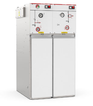
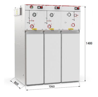
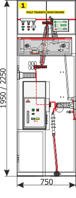
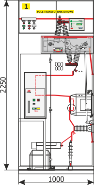
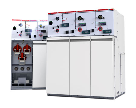
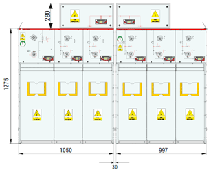
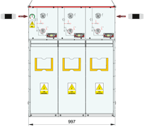
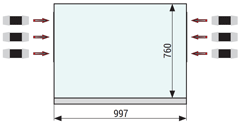
Design
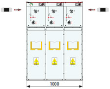
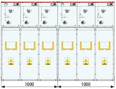
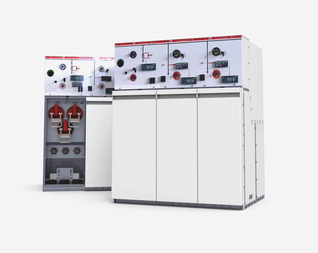
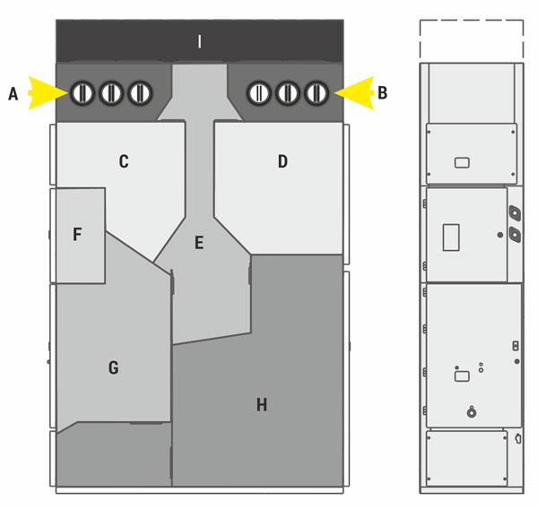
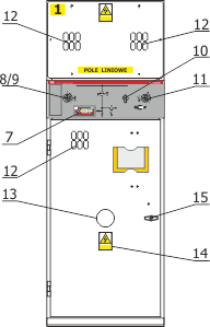
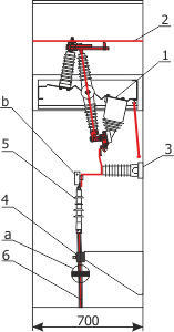
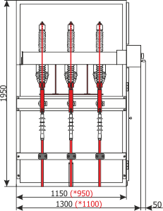
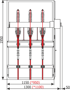
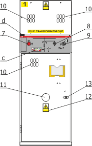
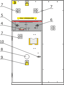
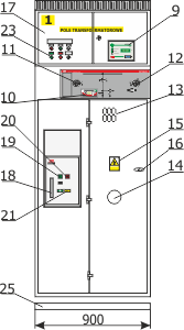
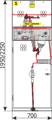
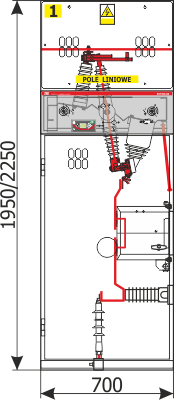
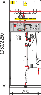
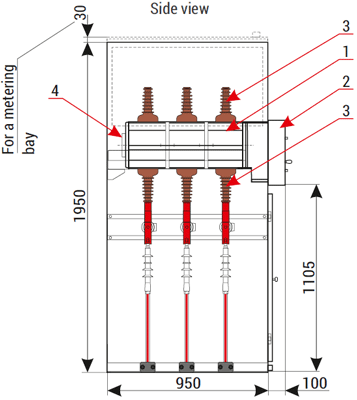
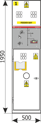
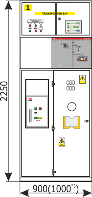
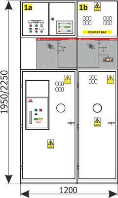
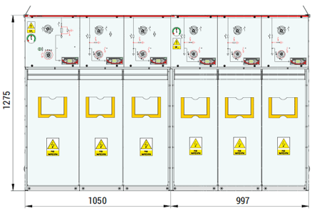
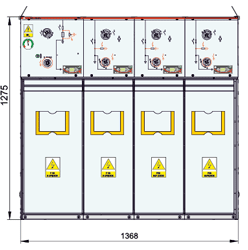
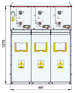
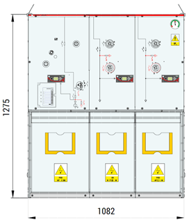
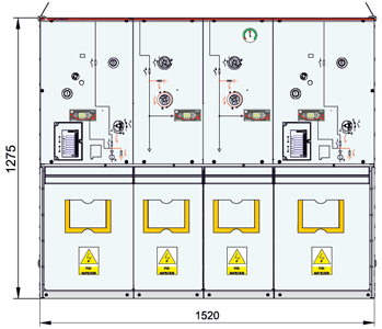
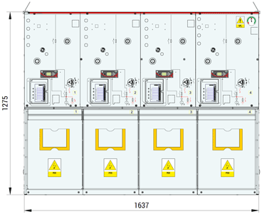
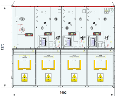
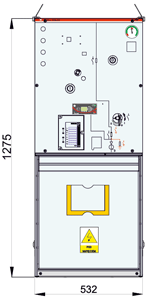
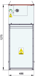
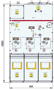
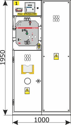
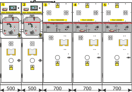
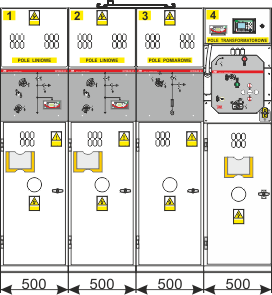
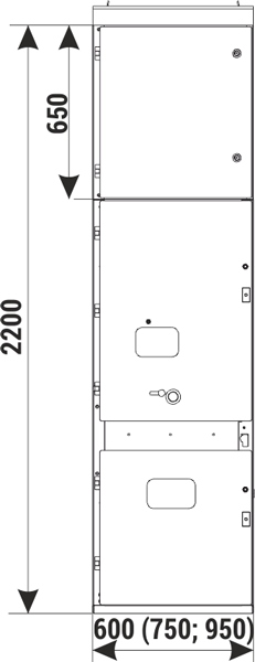
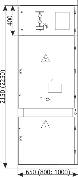
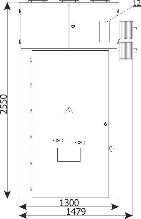
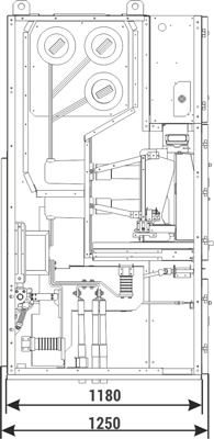
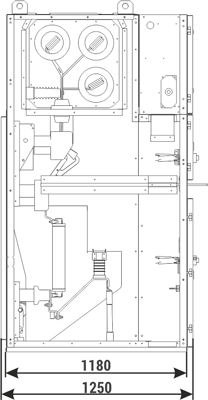
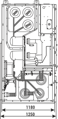
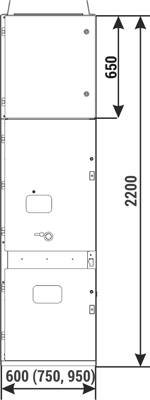
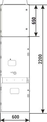
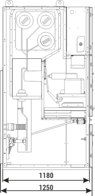
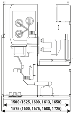
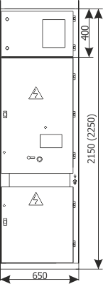
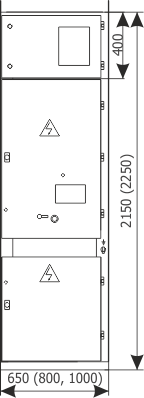
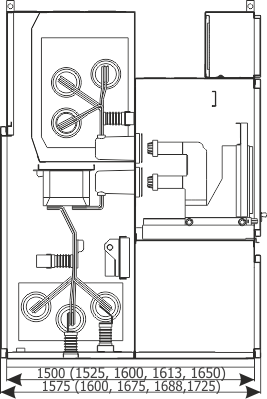
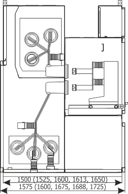
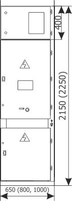
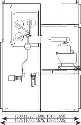
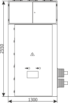
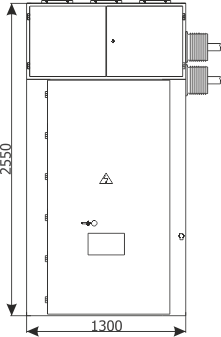
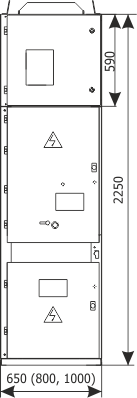
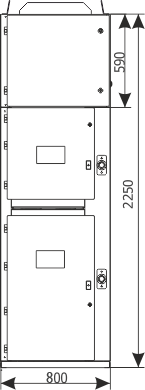
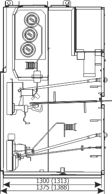
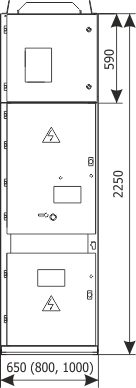
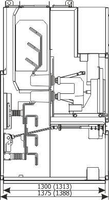
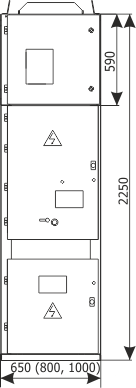
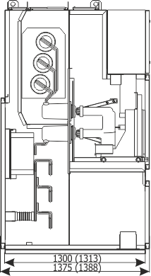
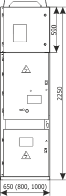
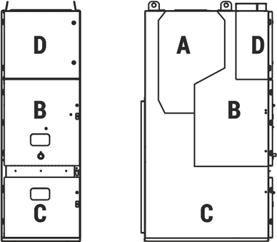
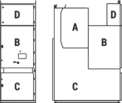
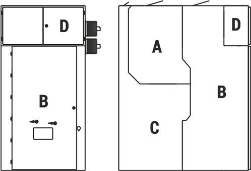
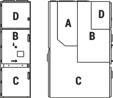
The RELF switchgear bay is designed as a cabinet divided into four separate functional compartments:
- busbars compartment (medium voltage circuits),
- main device compartment (medium voltage circuits),
- cable compartment (medium voltage circuits),
- auxiliary circuits LV compartment (low voltage circuits).
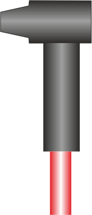
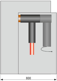
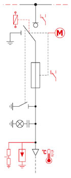
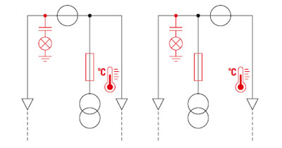
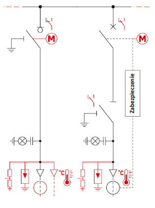
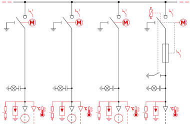
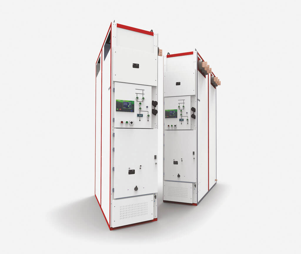
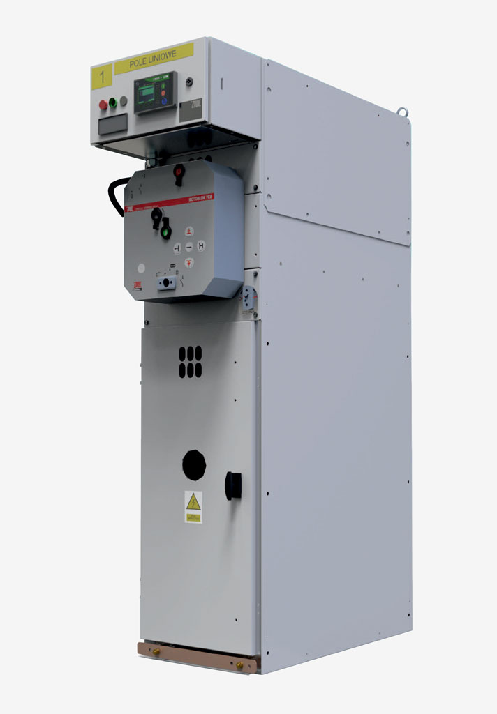
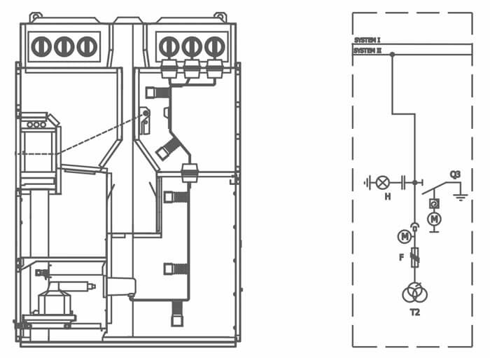
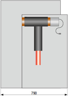
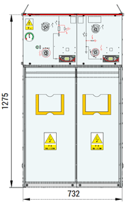
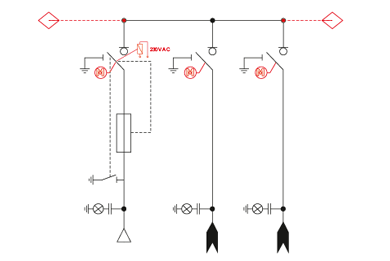
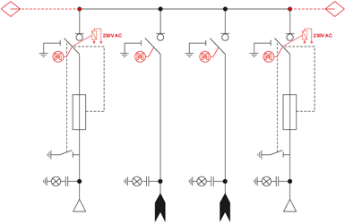
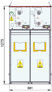
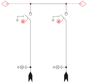
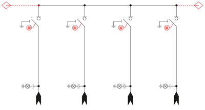
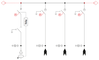
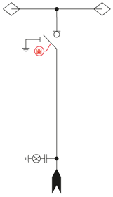
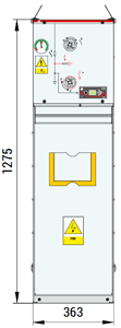
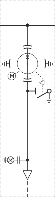
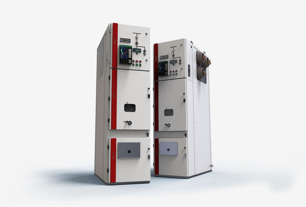
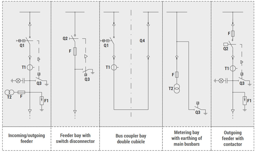
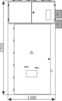
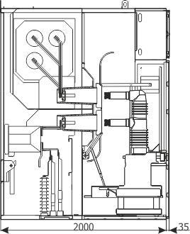
RELF version I
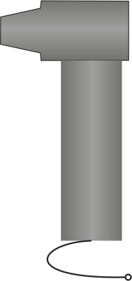
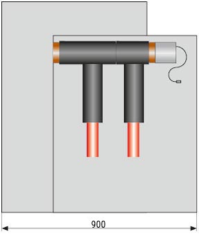
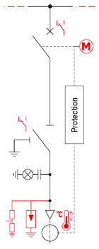
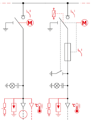
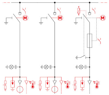
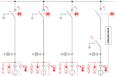
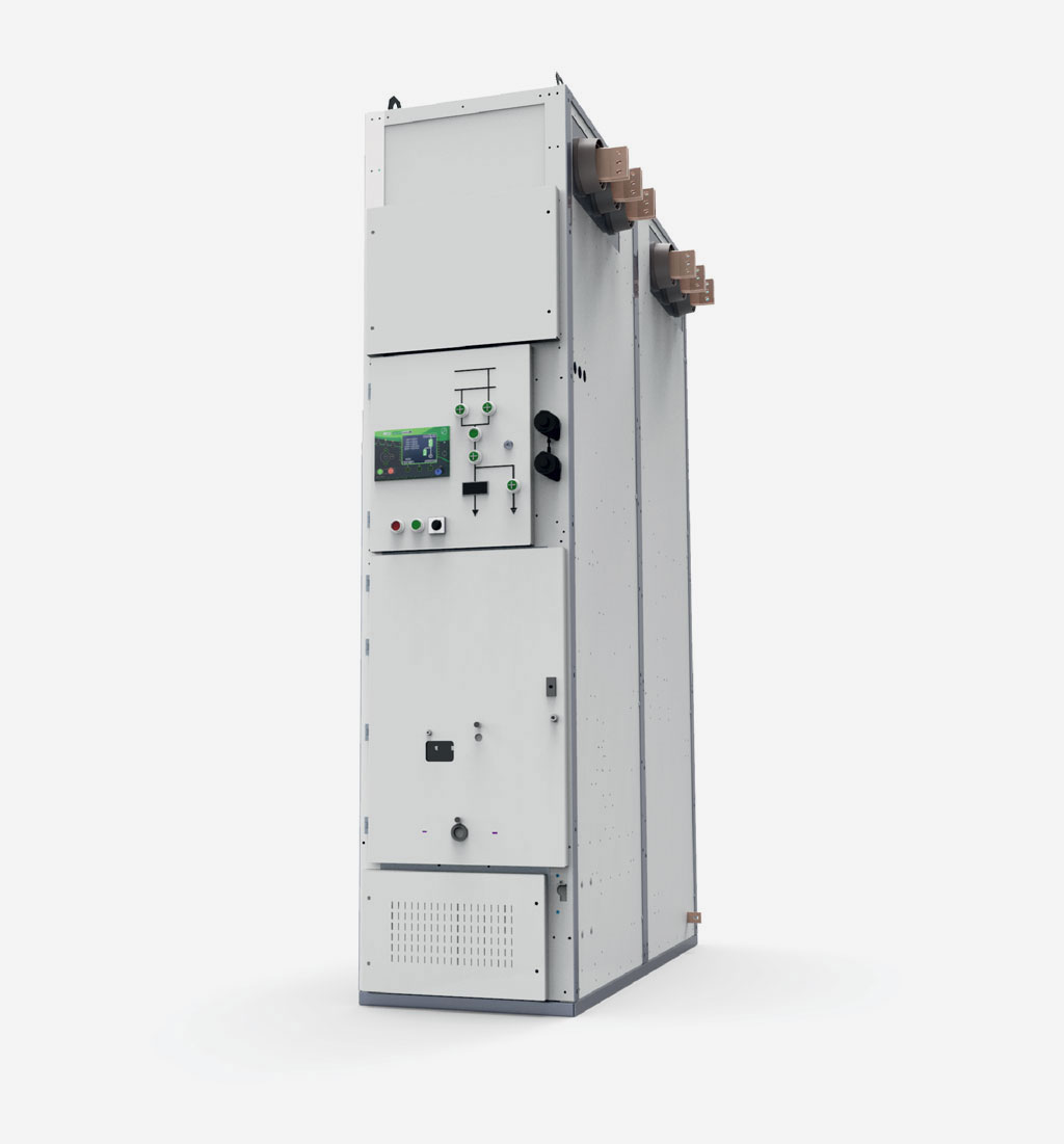
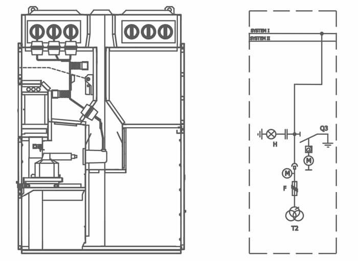
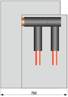
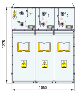
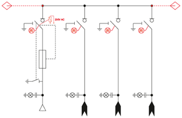
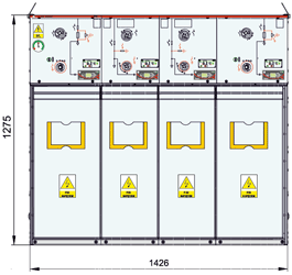
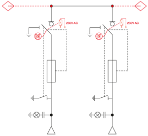
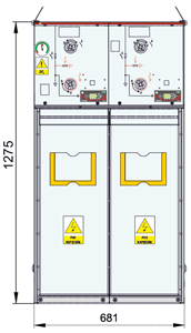
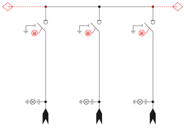
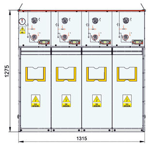
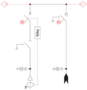
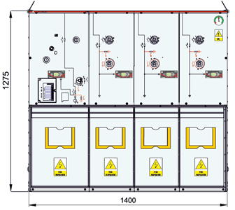
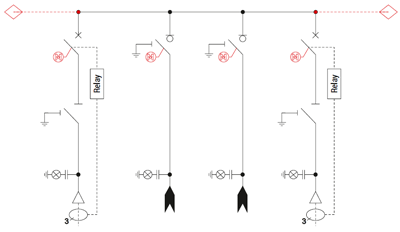
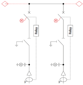
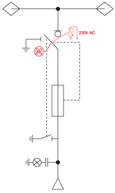
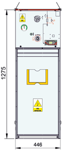
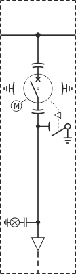
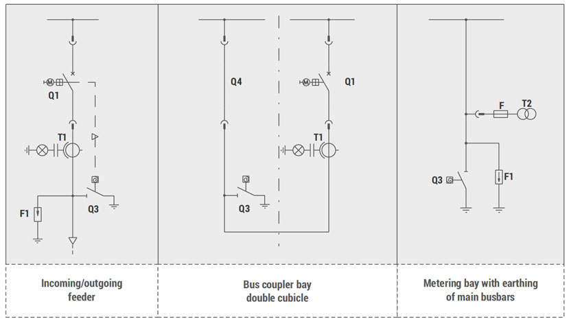
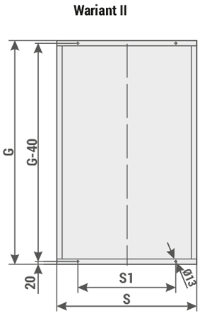
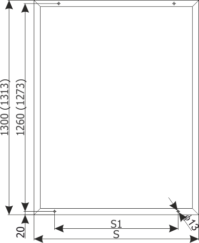
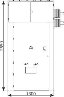
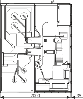
RELF version II
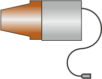
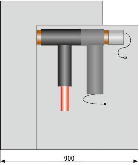
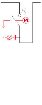
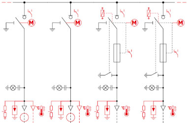
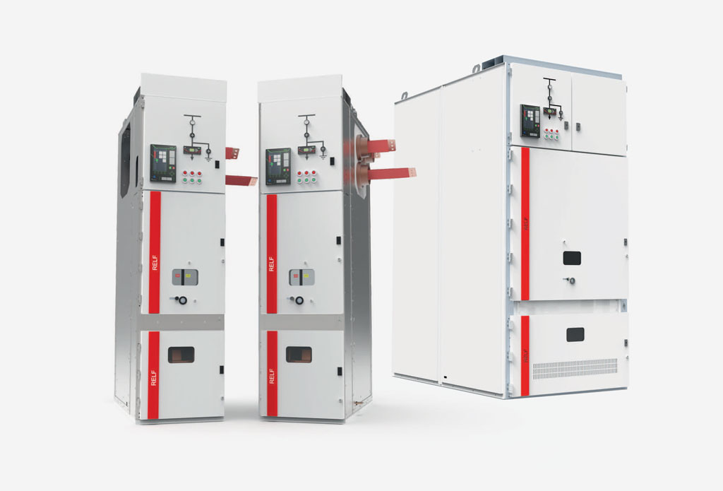
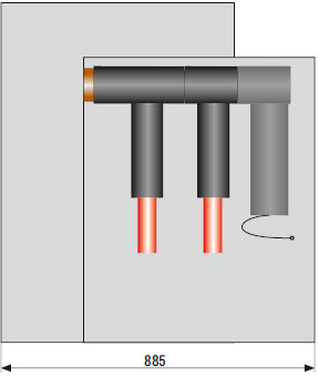
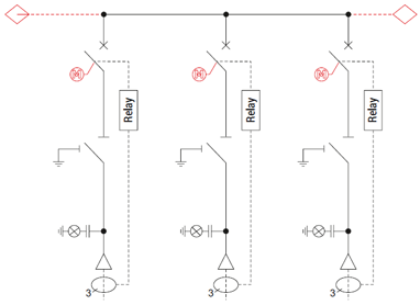
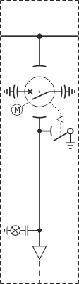
RELF 36
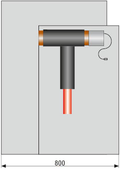
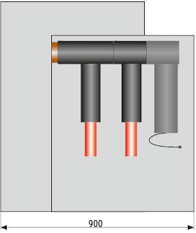
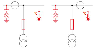
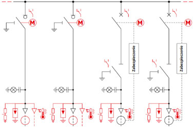
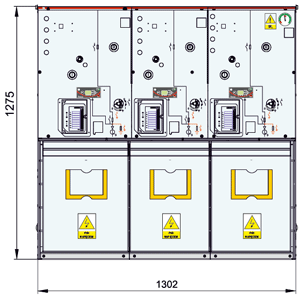
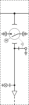
RELF ex
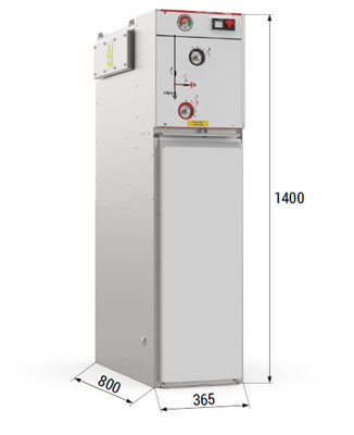
The switchgear cubicle is constructed of bent steel sheets, riveted together, without welding. Walls and partitions create a selfsupporting structure. A corrosion-resistant zinc-coated sheet is used for the construction of cabinets.
High-strength round-head steel rivets were used to connect structural elements. Functional compartments are limited by internal vertical and horizontal partitions. The internal partitions are attached to side walls, reinforcing and stabilising the entire enclosure. Additionally, two-part side covers made of painted sheet are bolted to the external walls of the outer bays of the switchgear.
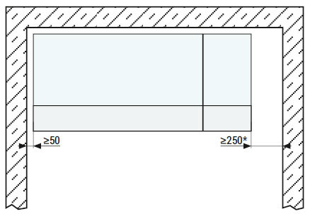
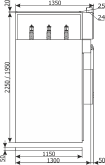
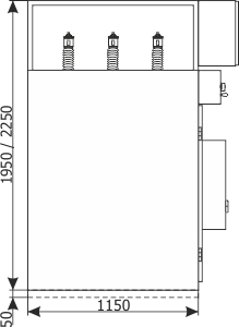
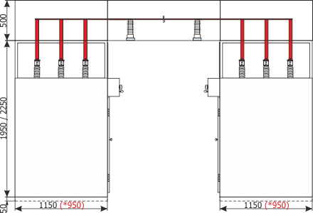
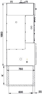
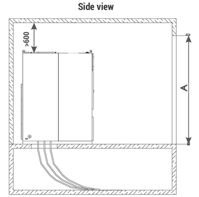
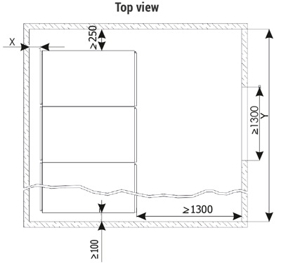
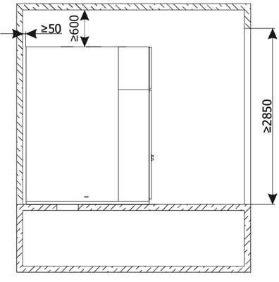
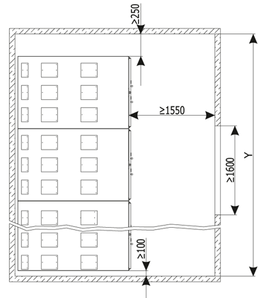
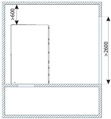
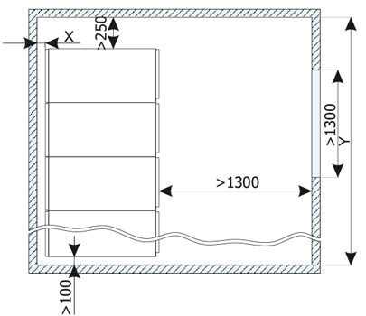
The switchgear may be constructed as free-standing or wall-standing. The front belt between the doors of the main device compartment and the doors to the cable connection compartment and the horizontal partition between these compartments are removable (does not apply to the RELF 36 version), which significantly facilitates maintenance and installations.
Internal partitions allow safe access to main device compartment and cable connection compartment, even when the primary busbars are live.
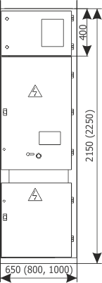
In accordance with the LSC (Loss of Service Continuity) category, the switchgear meets the criteria of LSC2B. This condition is met by switchgear with three MV compartments and the withdrawable module placed in the test/disconnection position.
The MV circuits compartment doors are made of powder coated sheet. Doors use hinges and bolts which can stand up to explosiontype loads. The hinges allow opening the doors by approximately 135º (170º in case of RELF 36). Upper and lower edges of the doors were reinforced by appropriately shaped and welded reinforcing profiles.
Doors to the main device compartment are equipped with an inspection window used for visual control of the position of the withdrawable module and switching operations.
The design of the doors allows the mechanical opening of the circuit breaker in operating position with the doors closed.
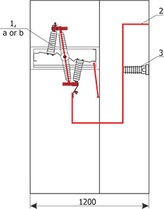
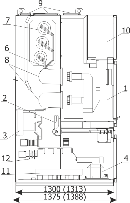
Blow-out flaps
All MV compartments have blow-out duct openings in their top zone, closed with flaps. Their task is to discharge any pressure created inside the compartment as a result of an internal arc fault.
A sudden increase of pressure inside the switchgear compartment breaks the plastic bolts and opens the flaps, which may activate limit switches installed at the roof of the switchgear. Limit switches activated by the flaps being opened send an impulse which trips the main circuit breaker. This allows limiting the effects of an arc fault generated inside the cubicle compartment.
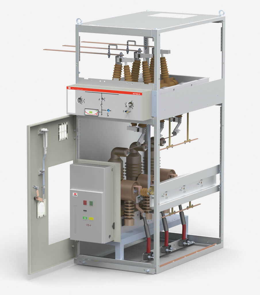
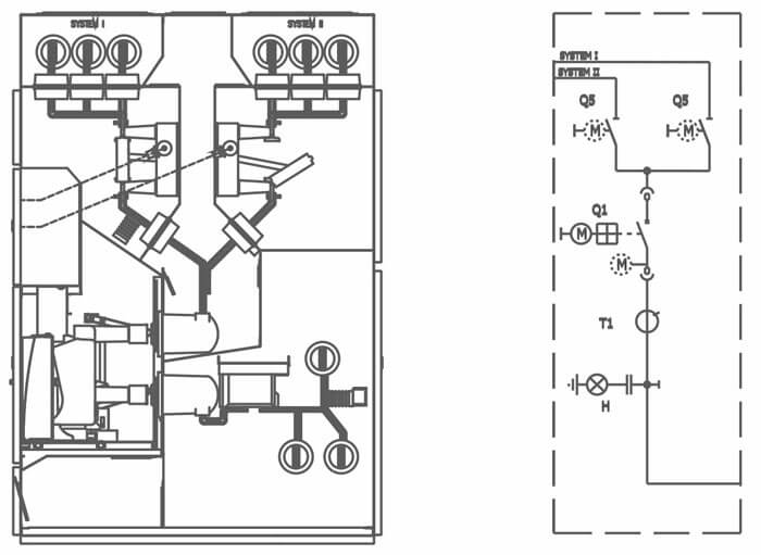
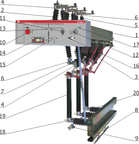
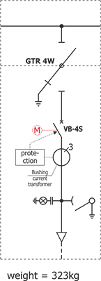
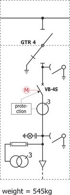
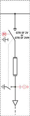
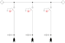
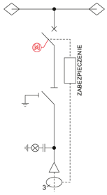
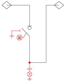
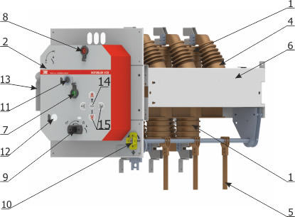
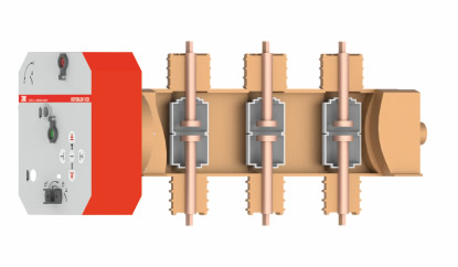
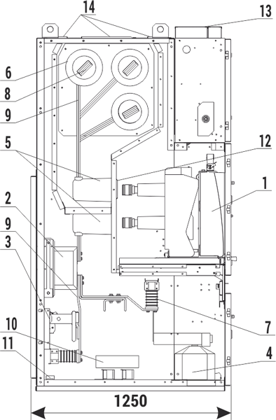
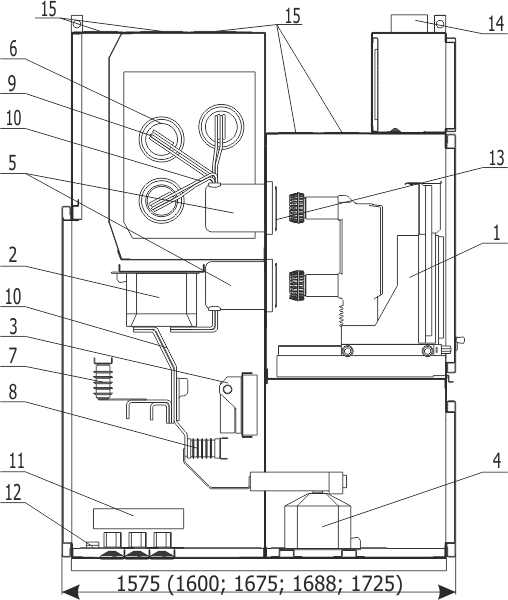
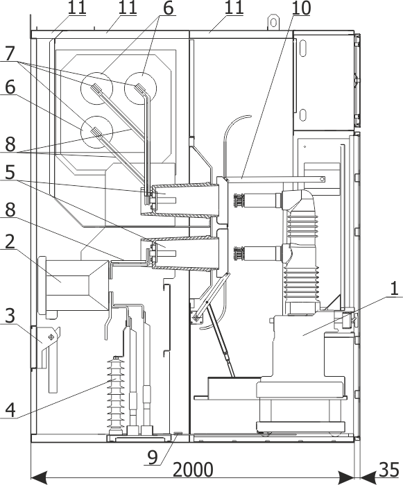
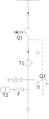
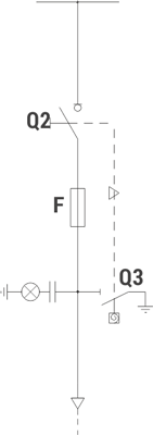
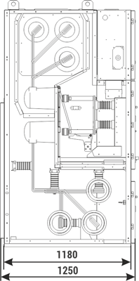
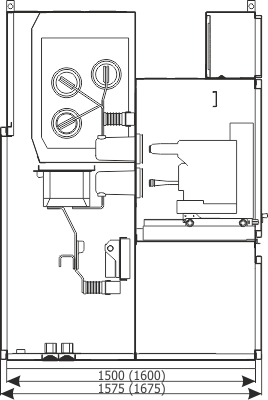
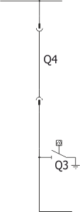
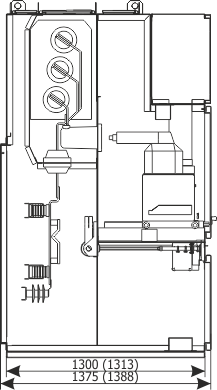
Withdrawable module
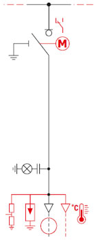
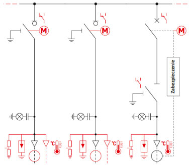
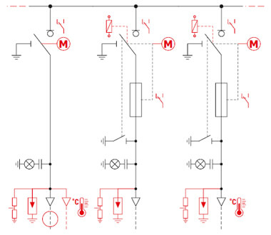
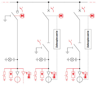
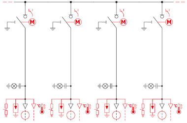
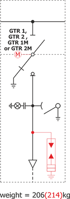
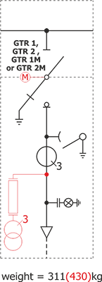
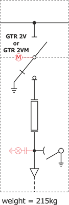
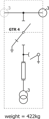
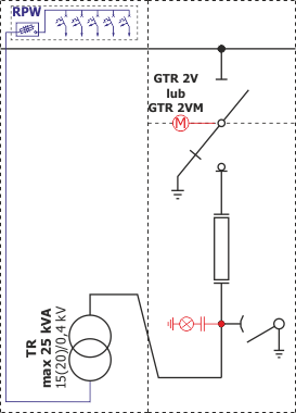
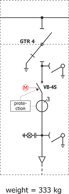
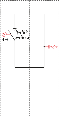
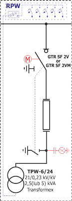
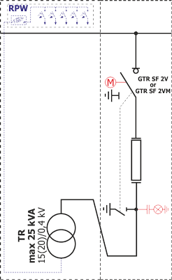
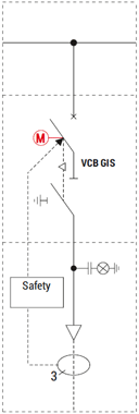
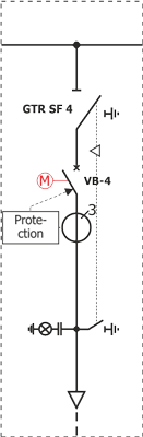
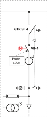
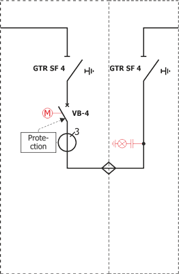
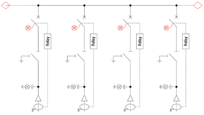
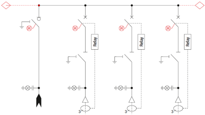
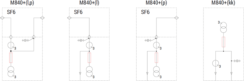
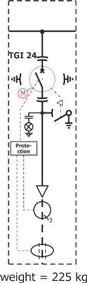
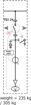
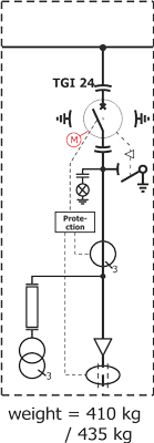
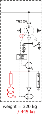
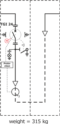
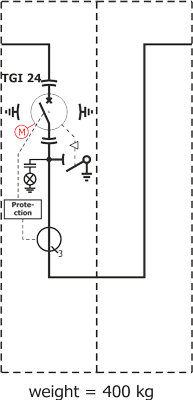
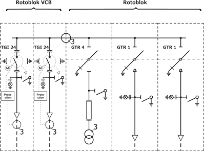
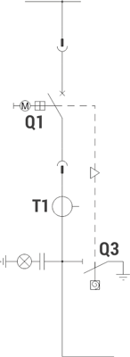
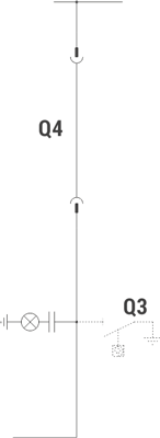
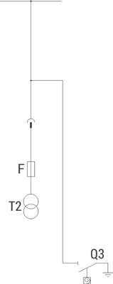
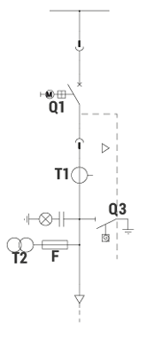
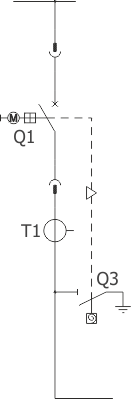
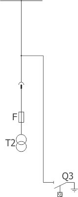
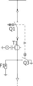
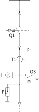
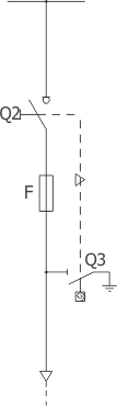
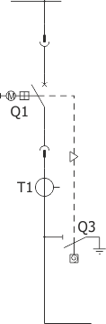
The withdrawable module is a unit composed of a racking system, and depending on the bay function: circuit breaker, contactor, set of fused voltage transformers, or a sectionalizer. The racking system performs the physical connection of the withdrawable module with the switchgear bay. It's stationary part is connected with the bay by interlocking on both sides in guide rail cut-outs.
The moving part of the racking system is shifted between the service position and the test/disconnection position using a drive screw operated manually with a crank, or with an electric drive, while the doors are closed. The service and test/disconnection position is signalled by position indicators, after the module reaches an appropriate position.
The shutters in the main device compartment are discussed in the main device compartment description.
Cubicle compartments
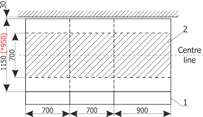
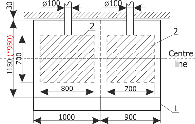
The busbars compartment is inaccessible during normal operation. For maintenance purposes access to busbars is possible from the top of the cabinet, after removing the blow-out flaps (or from the main device compartment side after removing the partition - for RELF 36). It is closed on both sides with gland plates made of non-magnetic steel sheet or insulating material. These plates prevent damage from spreading to adjacent bays in case of an electric arc in the busbars compartment.
Gland plates and bushings insulators are elements which support the busbars. Outgoing busbars branch off from the main busbars and enter the spouts which separate the busbar compartment from the main device compartment.
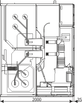
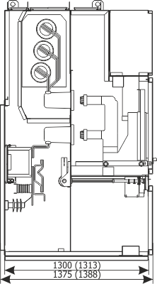
The main device compartment is available after its doors are open in an interlock-controlled mode. The main device compartment contains the withdrawable module and all the elements necessary for its operation with the cubicle bay, such as: withdrawable module guide rails, shutters, spouts with fixed contacts, door interlock and earthing switch interlock elements and auxiliary circuits socket/plug.
The spouts are installed in the partition separating the main device compartment from the cable connection compartment and busbars compartment. Fixed contacts and outgoing busbars are set in the spouts.
The shutters with an unlocking mechanism are installed in the main device compartment. Their task is to separate the compartment space from fixed contacts, which may be live when the withdrawable module is in the test/disconnection or separation position. A safe insulation space remains between the contacts and the closed shutters.
Racking in the withdrawable module from the test/disconnection position to the operating position causes the shutters to slide apart and the fixed contacts to be exposed, allowing the circuit breaker tulip contacts to connect.
Mechanical indicators of the circuit breaker position and drive charging state are visible through the inspection window.
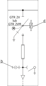
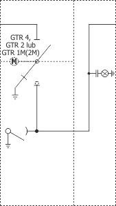
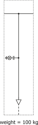
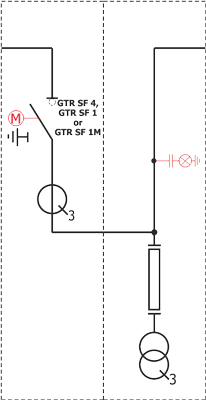
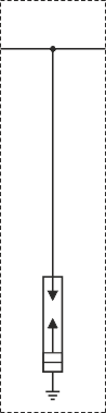
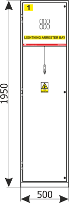
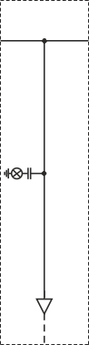
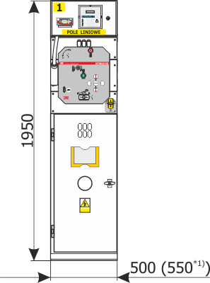
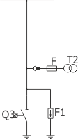
The cable connection compartment is designed to connect cables or busbars and is accessible after opening only the front doors (wall-standing version) or front and rear doors (free-standing version) in an interlock-controlled mode1). This compartment contains current transformers, an earthing switch, and depending on operational requirements, optionally: voltage transformers2), earth fault transformers and surge arresters.
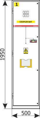
Voltage transformers are installed in the front part of the connection compartment (not in RELF 36kV).
The earthing switch is equipped with a manual drive, or a manual and motor drive. Its status is indicated by the position indicator.
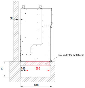
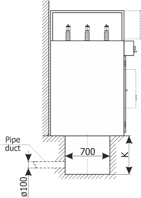
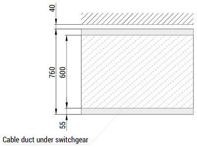
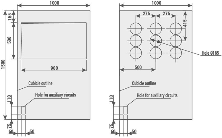
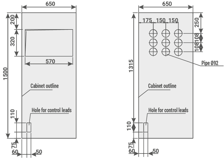
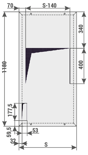
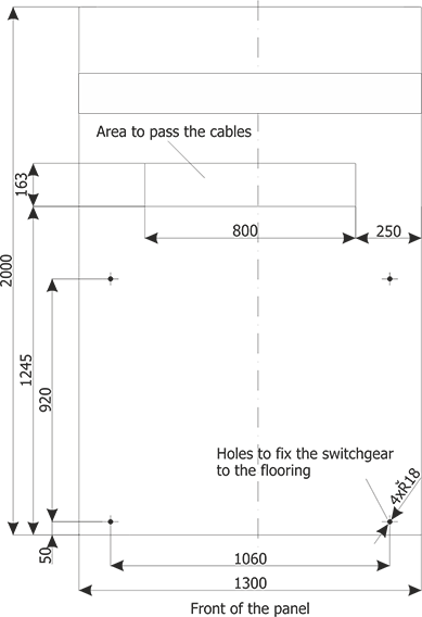
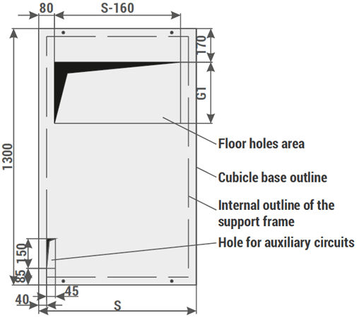
The compartment bottom is closed by a split floor cover, which also acts as a cable gland plate. Openings in the plate are covered with rubber cable glands. Cable clamps installed on supports are used to fasten the cables.
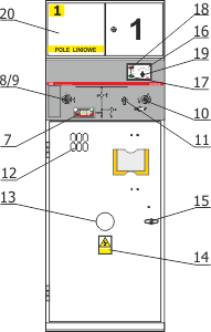
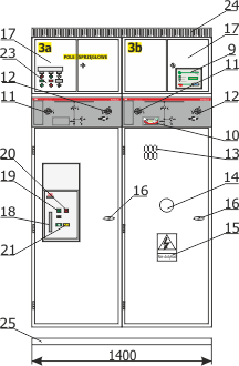
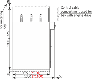
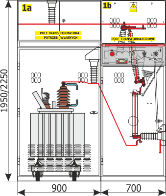
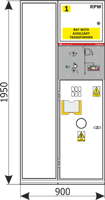
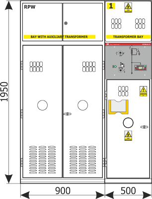
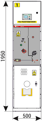
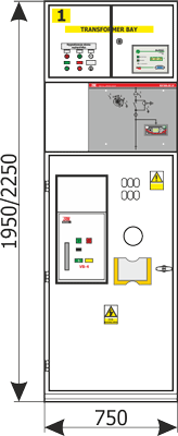
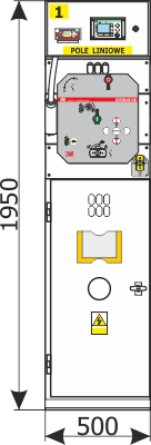
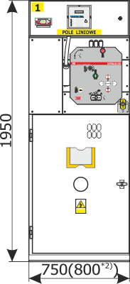
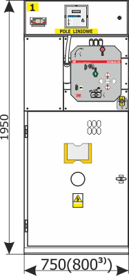
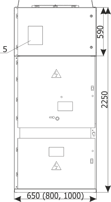
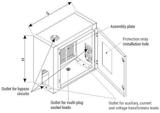
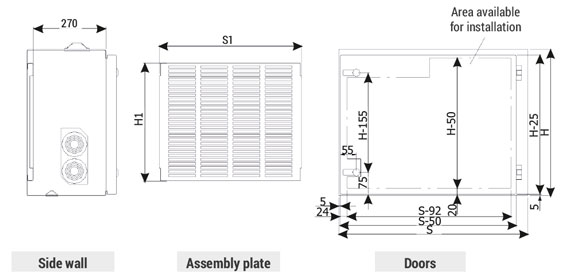
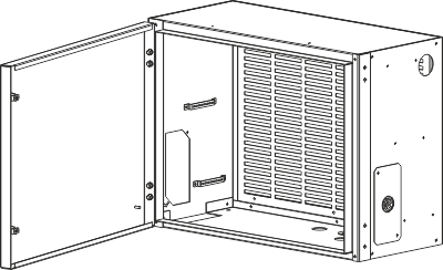
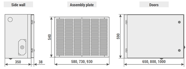
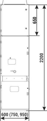
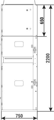
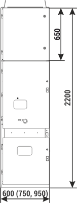
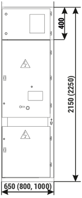
The auxiliary circuits LV compartment is constructed in the form of a control cubicle and is completely separated from the high voltage zone of the switchgear. The cubicle has its own sheet metal enclosure and is prefabricated independently of the high power part of the switchgear. It may be equipped with devices on a separate station, and then attached to the switchgear cabinet.
The cubicle is intended for the installation of: protection relays and IEDs, instrumentation & control devices and automation system elements.
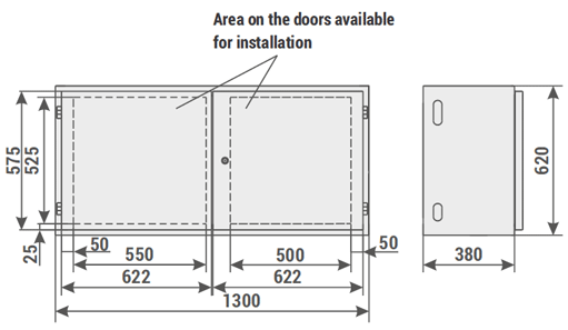
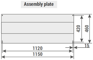
It is installed on the roof of the switchgear, above the switching device compartment. In its bottom, top and side walls a series of openings are made for lead and cable glands and cable trays. These openings are covered by plates, in which holes can be made according to design needs. An assembly plate fixed to the rear wall of the LV cubicle was designed for the installation of devices. The devices may be also fixed on the side walls. On arrangement with the manufacturer, the cubicle design may be adapted to individual needs of the customer and of the design.
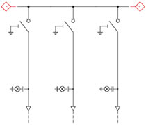
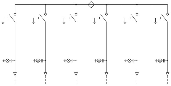
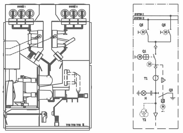
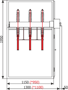
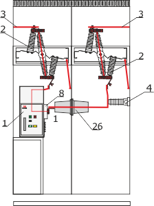
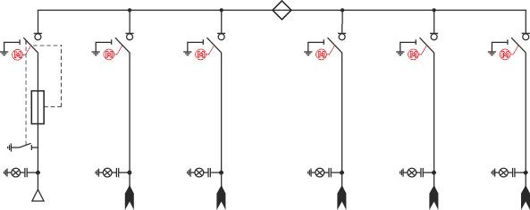
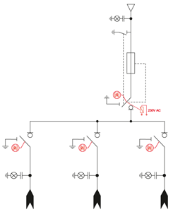
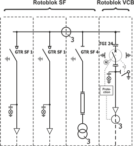
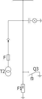
Main busbars
A single, three-phase busbar system is used in the switchgear. The busbars are installed in a separate compartment.
The main busbars are supported by distribution busbars which come out of the spouts and on insulating bushings installed in the side partitions.
Busbar cross-sections are selected in accordance with the rated current of the switchgear.
Insulating elements
The switchgear uses epoxy resin insulators. In the connection compartment the busbars are supported by post insulators.
For supporting the main busbars and passing them through switchgear bays, bushings are used, set in the gland plates of the bay side walls.
The passages through the partition between the switching device compartment and the busbars compartment and the connection compartment are provided by spouts.
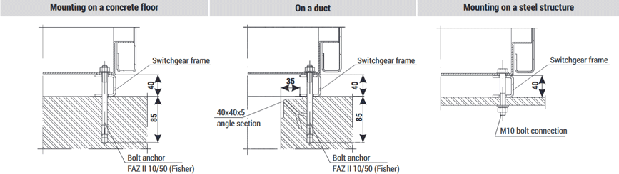
Protective earthing
An earthing conductor is placed in every cabinet, in the form of a copper busbar with a cross-section of 40x10 mm, placed at the bottom of the cabinet. These busbars are bridged between the cabinets, creating an earthing conduit. The conduit is terminated by terminals on the left and right side of the switchgear, used to connect it to the facility's earthing system.
Cable connections
The connection compartments are designed for entry of single- or multi-core MV cables.
1) in the RELF 36 version the connection compartment is accessible after opening the cabinet doors and removing the partition on the side of the switching device compartment.
2) does not apply to the RELF 36 version.