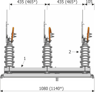
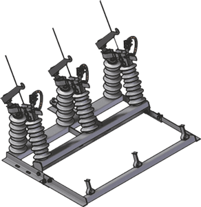
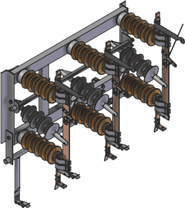
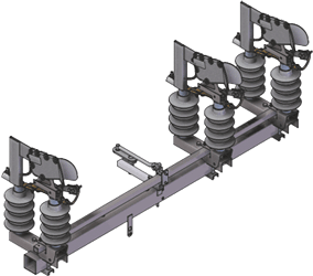
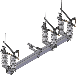
Connectors are three-pole appliances with one drive. Each pole is equipped with two supporting insulators – fixed or movable. Connectors can be equipped with porcelain, composite insulators with cycloaliphatic resin or silicone in an HTV rubber cover. Handles with main contacts are installed to the insulators. The main contacts are made from tinning coated, profiled copper flat bars. The construction of the contacts allows their self-guidance, and provides a large contact surface and clamping force.
Appliances, as standard, are equipped with current terminals, which allow the installation of isolated or naked aluminum electricity cables with a cross-section of 16-95 mm2 (a special design allows connecting cables with a cross-section of 120 mm2). This information must be provided while placing an order or request. Additionally, appliances with earthing switches are equipped with a flexible contact, which takes over the effects of bending on a movable appliance pole.
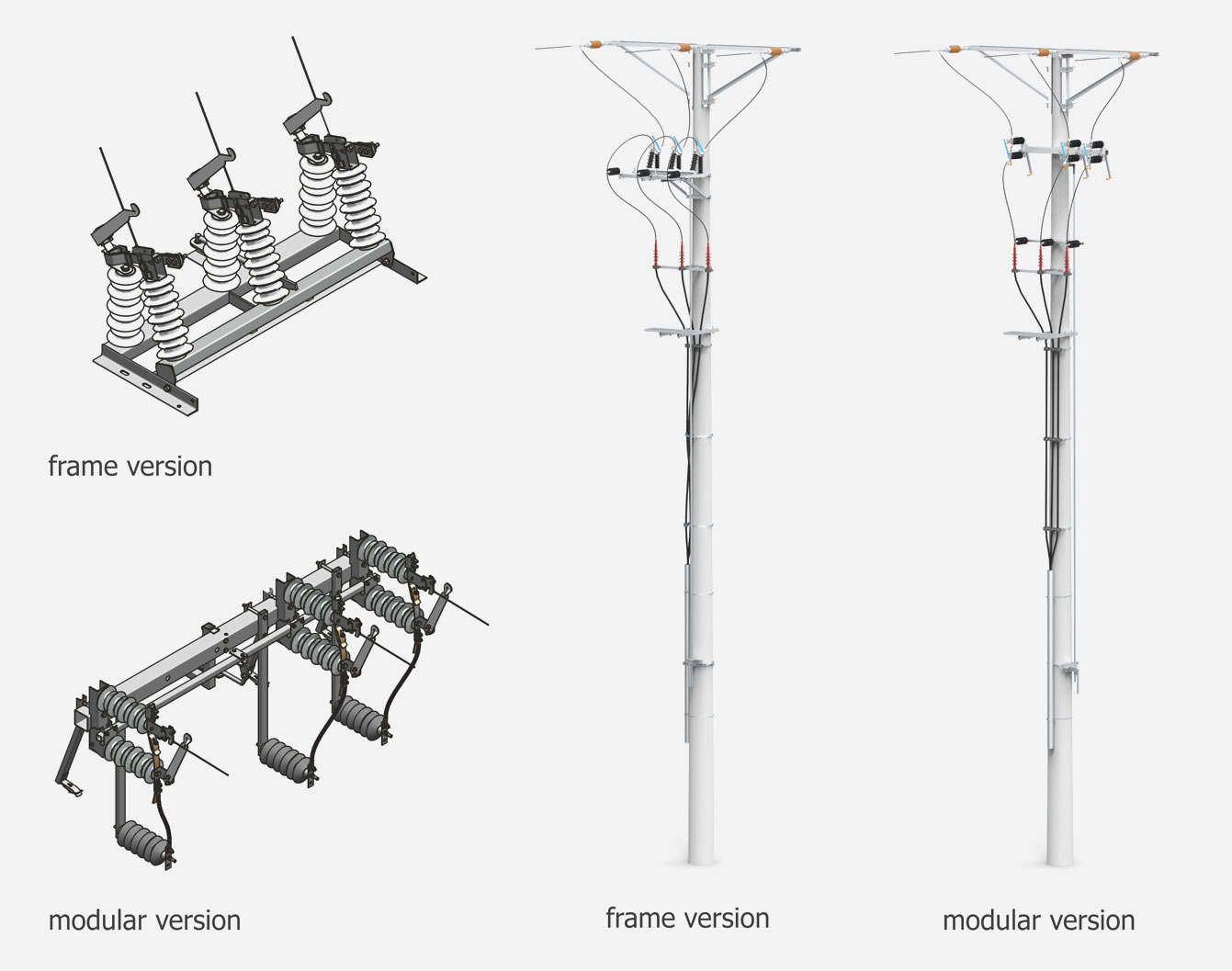
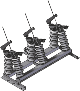
Connectors in the modular structure can be expanded with additional elements such as: lightning arresters, additional support insulators. They can be installed in the horizontal or vertical position.
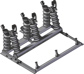
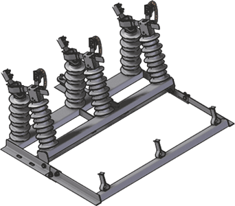
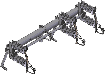
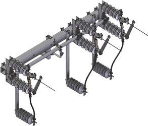
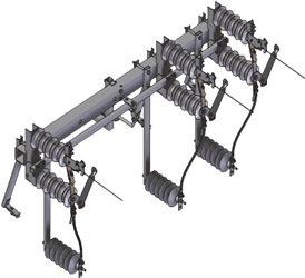
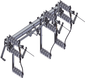
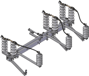
View, dimensions and construction of the connectors
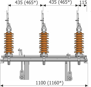
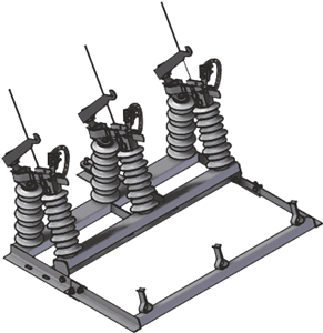
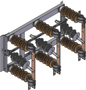
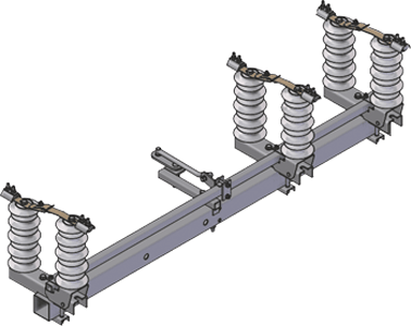
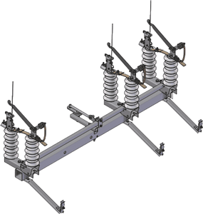
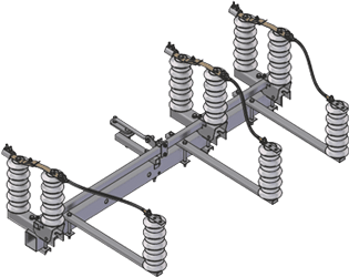
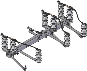
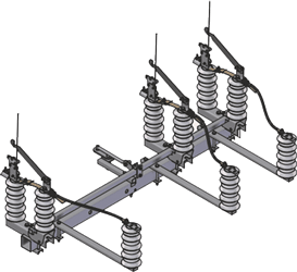
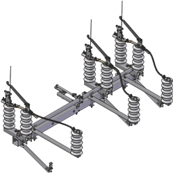
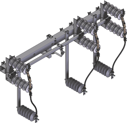
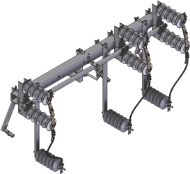
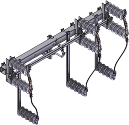
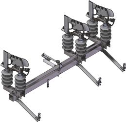
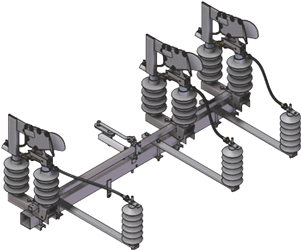
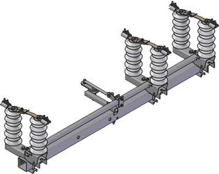
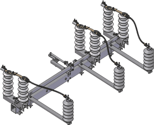
View, dimensions and construction of the modular connectors
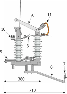
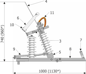
- switch disconnector frame (beam)
- bushing insulator
- switch disconnector main contacts
- snap action movable contacts
- movable support
- snap action contact
- earthing switch contact
- earthing switch supporting structure
- drive lever of the switch disconnector
- connection terminal
- oscillating element with a terminal strip
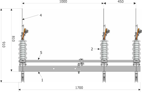
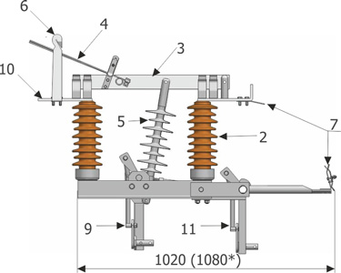
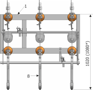
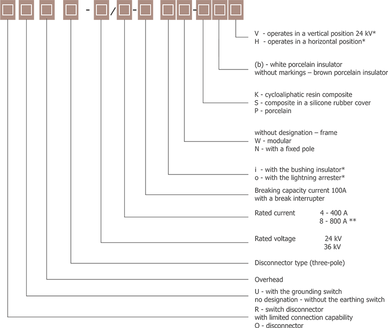
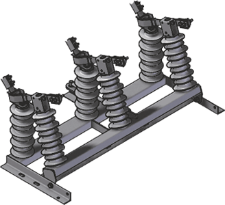
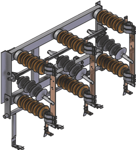
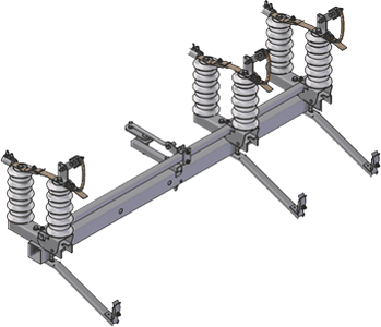
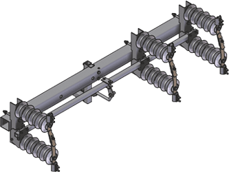
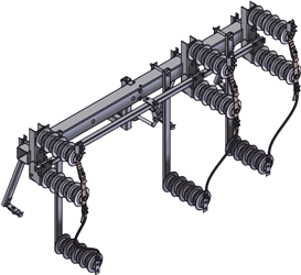
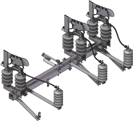
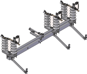
View, dimensions and construction of the frame connectors
- switch disconnector frame (beam)
- bushing insulator
- switch disconnector main contacts
- snap action movable contacts
- movable support
- snap action contact
- earthing switch contact
- earthing switch supporting structure
- drive lever of the switch disconnector
- connection terminal
- oscillating element with a terminal strip
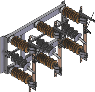
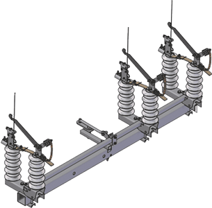
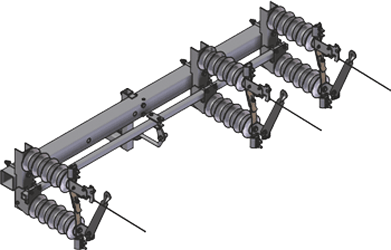
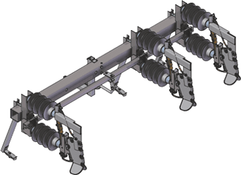
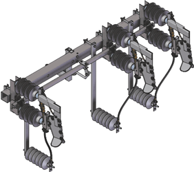
Connectors with limited capability rated continuous current 800A

The Connector structure refers to well-known power industry solutions, which have been in use for many years now. A modified contact system allows the transmission and switching capability to be increased. The application of silicone drive insulators eliminates the risk of damage to this element. The main shaft interlock prevents faulty switching operations and considerably improves the handling safety of the appliance. Connectors can be equipped with porcelain, composite insulators with cycloaliphatic resin or silicone in an HTV rubber cover. Contact elements applied from our production units guarantees the proper electrical and mechanical operation of the appliance. Appliances are designed to power lines with considerable cable cross-sections up to 240 mm2, overhead switchgear busbar bridges and stations 110 kV/15 – 24 – 36 kV and for cable trays. Standard hand drives manufactured by ZPUE S.A. are used to control the connectors.
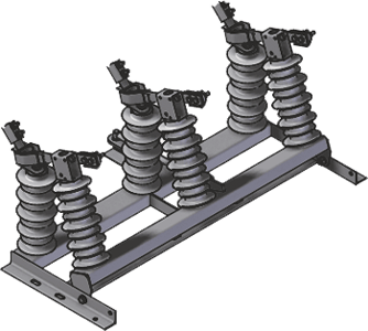
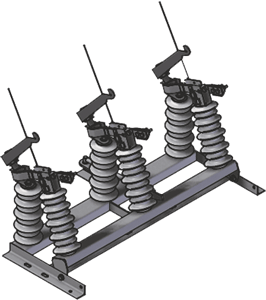
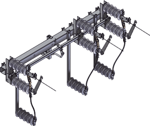
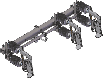
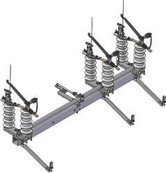
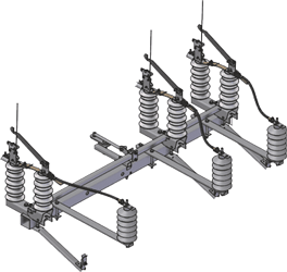
View, dimensions and construction of the connectors 800A
- switch disconnector frame (beam)
- bushing insulator
- switch disconnector main contacts
- snap action movable contacts
- movable support
- snap action contact
- earthing switch contact
- earthing switch supporting structure
- switch disconnector drive mechanism
- place for cable connection
- earthing switch drive mechanism
Connectors with limited connection capability - connectors designation
RUN III 24/4 P
Stands for an overhead, three-pole switch disconnector
with the earthing switch for the rated voltage 24 kV and rated continuous current 400 A.
ON III 24/4 P
Stands for an overhead, three-pole disconnector
for the rated voltage 24 kV and rated continuous current 400 A.
RUN III 24/4 o W-S-V
Stands for an overhead, three-pole switch disconnector
with the earthing switch 24 kV/400 A with an arrester, modular
composite insulators in a silicone rubber cover designed for vertical installation
OUN III 24/8 N-S
Overhead, three-pole disconnector with the earthing switch
24 kV/800 A with a fixed pole, composite insulators in a silicone rubber cover
OUN III 36/8 N-S
Overhead, three-phase disconnector with the earthing switch
36 kV/800 A with a fixed pole, composite insulators in a silicone rubber cover
* refers to the modular connectors
** refers to the fixed pole
Frame versions connectors
P (51,5 kg)
S (41,3 kg)
K (47,5 kg)
P (53,5 kg)
S (43,3 kg)
K (49,5 kg)
P (51,7 kg)
S (41,5 kg)
K (47,7 kg)
P (53,7 kg)
S (43,5 kg)
K (49,7 kg)
P (68,7 kg)
S (53,3 kg)
K (59,5 kg)
P (73,3 kg)
S (55,3 kg)
K (64,1 kg)
P (69,0 kg)
S (53,8 kg)
K (59,8 kg)
P (73,7 kg)
S (55,7 kg)
K (64,5 kg)
P (80,2 kg)
S (70,0 kg)
K (74,5 kg)
P (90,2 kg)
S (78,0 kg)
K (82,5 kg)
P (100 kg)
S (85,0 kg)
K (92,0 kg)
P (108 kg)
S (93,0 kg)
K (98,5 kg)
The manufacturer reserves the right to make construction modifications at any time, which may result in a change of the device’s weight and dimensions.
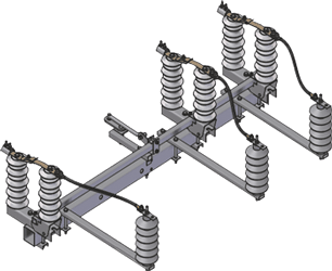
Modular connectors in a basic version (horizontal)
P (59,5 kg)
S (49,3 kg)
K (57,5 kg)
P (61,5 kg)
S (51,5 kg)
K (58,5 kg)
P (61,5 kg)
S (51,5 kg)
K (59,5 kg)
P (63,5 kg)
S (53,3 kg)
K (60,0 kg)
The manufacturer reserves the right to make construction modifications at any time, which may result in a change of the device’s weight and dimensions.
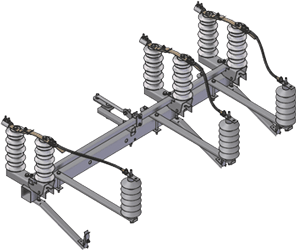
Modular connectors in a basic version (vertical)
P (59,5 kg)
S (49,3 kg)
K (57,5 kg)
P (61,5 kg)
S (51,5 kg)
K (58,5 kg)
P (61,5 kg)
S (51,5 kg)
K (59,5 kg)

P (63,5 kg)
S (53,3 kg)
K (60,0 kg)
The manufacturer reserves the right to make construction modifications at any time, which may result in a change of the device’s weight and dimensions.
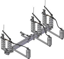
Modular connectors with the construction for lightning arresters installation (horizontal)
P (65,5 kg)
S (55,3 kg)
K (63,5 kg)
P (67,5 kg)
S (57,3 kg)
K (65,5 kg)
P (67,5 kg)
S (57,3 kg)
K (65,5 kg)
P (69,5 kg)
S (59,3 kg)
K (67,5 kg)
The manufacturer reserves the right to make construction modifications at any time, which may result in a change of the device’s weight and dimensions.
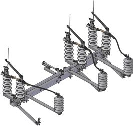
Modular connectors with the construction for support insulators installation (horizontal)
P (65,5 kg)
S (55,3 kg)
K (63,5 kg)
P (67,5 kg)
S (57,3 kg)
K (65,5 kg)
P (67,5 kg)
S (57,3 kg)
K (65,5 kg)
P (69,5 kg)
S (59,3 kg)
K (67,5 kg)
The manufacturer reserves the right to make construction modifications at any time, which may result in a change of the device’s weight and dimensions.
Modular connectors with the construction for lightning arresters installation (vertical)
P (65,5 kg)
S (55,3 kg)
K (63,5 kg)
P (67,5 kg)
S (57,3 kg)
K (65,5 kg)
P (67,5 kg)
S (57,3 kg)
K (65,5 kg)
P (69,5 kg)
S (59,3 kg)
K (67,5 kg)
The manufacturer reserves the right to make construction modifications at any time, which may result in a change of the device’s weight and dimensions.
Modular connectors with the construction for support insulators installation (vertical)
P (65,5 kg)
S (55,3 kg)
K (63,5 kg)
P (67,5 kg)
S (57,3 kg)
K (65,5 kg)
P (67,5 kg)
S (57,3 kg)
K (65,5 kg)
P (69,5 kg)
S (59,3 kg)
K (67,5 kg)
The manufacturer reserves the right to make construction modifications at any time, which may result in a change of the device’s weight and dimensions.
Modular connectors with air interrupters 100 A (horizontal)
P (63,5 kg)
S (53,3 kg)
K (61,5 kg)
P (65,5 kg)
S (55,5 kg)
K (62,0 kg)
The manufacturer reserves the right to make construction modifications at any time, which may result in a change of the device’s weight and dimensions.
Modular connectors with air interrupters 100 A (vertical)
P (63,5 kg)
S (53,3 kg)
K (61,5 kg)
P (65,5 kg)
S (55,5 kg)
K (62,0 kg)
The manufacturer reserves the right to make construction modifications at any time, which may result in a change of the device’s weight and dimensions.
Modular connectors for 36 kV with the construction for lightning arresters installation (horizontal)
P (69,5 kg)
S (59,5 kg)
K (67,5 kg)
P (71,5 kg)
S (61,3 kg)
K (69,5 kg)
The manufacturer reserves the right to make construction modifications at any time, which may result in a change of the device’s weight and dimensions.
Modular connectors with the construction for lightning arresters installation (vertical)
P (69,5 kg)
S (59,5 kg)
K (67,5 kg)
P (71,5 kg)
S (61,3 kg)
K (69,5 kg)
The manufacturer reserves the right to make construction modifications at any time, which may result in a change of the device’s weight and dimensions.
Modular connectors for 36 kV in a Basic version (horizontal)
P (64,0 kg)
S (54,3 kg)
K (62,5 kg)
P (66,5 kg)
S (56,5 kg)
K (63,5 kg)
P (66,5 kg)
S (56,5 kg)
K (64,5 kg)
P (68,5 kg)
S (58,5 kg)
K (65,0 kg)
The manufacturer reserves the right to make construction modifications at any time, which may result in a change of the device’s weight and dimensions.
Modular connectors for 36 kV with the construction for lightning arresters installation (horizontal)
P (73,5 kg)
S (64,8 kg)
K (72,5 kg)

P (77,5 kg)
S (66,0 kg)
K (75,0 kg)
P (76,5 kg)
S (67,3 kg)
K (75,0 kg)
P (79,5 kg)
S (68,5 kg)
K (77,5 kg)
The manufacturer reserves the right to make construction modifications at any time, which may result in a change of the device’s weight and dimensions.