
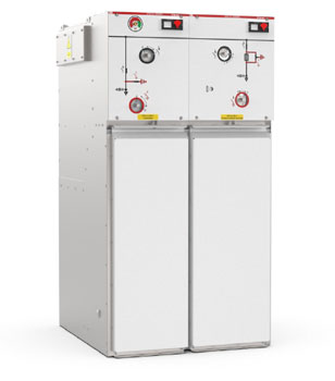
The TPM Air switchgear is a modern ring main unit (RMU) designed for use in medium-voltage networks. The design is based on dry air insulation and vacuum technology, using only natural components of atmospheric air, which ensures full compliance with current environmental requirements and future regulations on greenhouse gases. TPM Air meets the requirements for distribution switchgear, combining environmental considerations with the advantages of the proven TPM switchgear concept. It is a groundbreaking solution that guarantees safe, economical and long-term operation of MV networks.
Characteristics
Characteristics
- miniature switchgear dimensions while maintaining high technical parameters,
- high level of operational safety thanks to a design that ensures resistance to internal arcing on all sides of the switchgear,
- possibility of configuring a switchgear from a series of panels for various purposes: line panels, transformer panels, switch panels, coupling panels, measuring panels,
- the switchboard can be easily expanded with additional sets (this should be taken into account when placing an order); each set can be manufactured as expandable,
- the possibility of adapting the switchgear to work with remote control and measurement systems, e.g. to work with SmartGrid networks,
- a quick earthing device that grounds the fuse link on both sides in the transformer field,
- tank made of stainless and acid-resistant steel, filled with dry air under overpressure; thanks to its sealed design, it does not require maintenance throughout its entire service life,
- insulating medium consisting of natural components of atmospheric air – no global warming potential (GWP).
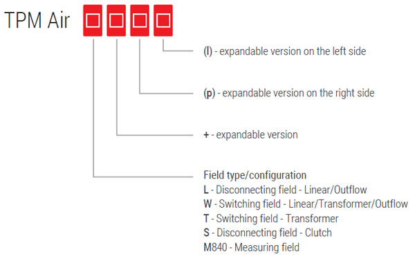
Possible markings/nomenclature
Standards
The TPM Air switchgear complies with the requirements of the following standards:
- PN-EN 62271-1 - „High-voltage switchgear and controlgear – Part 1: Common provisions”,
- PN-EN 62271-200 - „High-voltage switchgear and controlgear – Part 200: AC switchgear in metal enclosures for rated voltages above 1 kV up to and including 52 kV”,
- PN-EN 62271-100 - „High-voltage switchgear and controlgear – Part 100: High-voltage alternating current circuit breakers”,
- PN-EN 62271-102 - „High-voltage switchgear and controlgear – Part 102: High-voltage AC disconnectors and earthing switches”,
- PN-EN 62271-103 - „High-voltage switchgear and controlgear – Part 103: Disconnectors with a rated voltage exceeding 1 kV up to and including 52 kV”,
- PN-EN 62271-105 - „High-voltage switchgear and controlgear – Part 105: AC fuse switchgear assemblies”,
- PN-EN 62271-213 - „High-voltage switchgear and controlgear – Part 213: Voltage detection and indication system”.
Field equipment
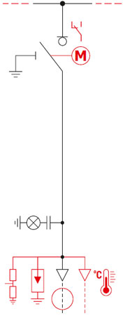
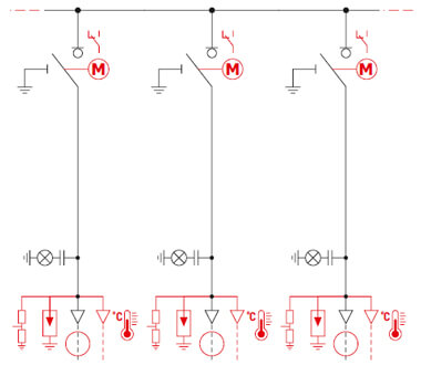
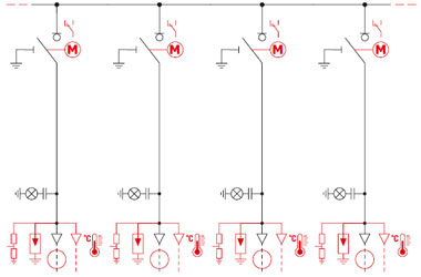
L-field equipment – disconnectors (line, supply, outlet)
| Basic parameters | |
| Ur | 25 kV |
| Fr | 50/60 Hz |
| Ud | 50/60 kV |
| Up | 125/145 kV |
| Ir | 630 A |
| Ik | up to 20 kA (1s) |
| Ip | up to 50 kA |
| Ima | up to 50 kA |
| Icc2 | 70 A |
| M2, E3, C2 disconnector class | |
| M1, E2 earthing switch class | |
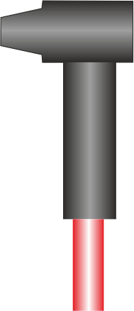
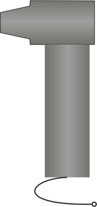
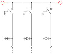
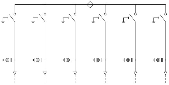
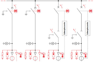
Optional equipment is marked in red on the wiring diagram.
Some optional equipment may be mutually exclusive or require the use of a deep cable compartment cover.
- compliance with PN-EN 62271-103, Disconnectors with rated voltage above 1kV up to and including 52kV,
- compliance with PN-EN 62271-102, High-voltage AC disconnectors and earthing switches,
- L field as a single module with an expansion option or can be combined with other configurations within a common tank in systems with up to four fields,
- three-position disconnector-earthing switch assembly, whose design is based on common moving contacts and separate fixed contacts of the earthing switch and disconnector,
- disconnector equipped with a shunt current interruption system in a vacuum chamber during disconnection,
- a manual drive ensuring intuitive and easy manoeuvring and quick closing and opening of the switching equipment,
- a synoptic display showing the status of the devices and entire main circuits,
- C-type bushings with M16 thread equipped with capacitive voltage dividers designed to work with voltage indicators in the LRM system and with electromagnetic interlocks,
- signal indicator of voltage presence on the cable in the LRM system,
- pressure gauge – gas pressure indicator with a two-zone scale, indicating the nominal absolute gas pressure (dry air) of -250 kPa (0.25 MPa) at a temperature of 20°C (one per tank),
- a system of mechanical locks between the devices and the cable compartment covers to prevent incorrect connection operations – the cover can only be removed after the earthing switch has been closed,
- safety valve (one for each tank), which opens when the pressure inside the tank rises due to an arc, directing the gases downwards into the cable duct, thus eliminating the risk to personnel,
- cable holders.
- 24V DC motor drive (other supply voltages available on request), can be retrofitted on site,
- pressure sensor (density meter) with auxiliary contacts – for use with motor drive, telemechanics,
- auxiliary contacts enabling the mapping of device statuses in telemechanics systems,
- voltage sensors - low-power transformers,
- current transformers, current sensors, Rogowski coils,
- earth fault transformers,
- short-circuit current flow indicators,
- auxiliary circuit cabinet/cooperation with telemechanics,
- ‘ON’ and ‘OFF’ signalling in the form of indicator lights,
- anti-condensation heaters,
- expansion possible on the right and left sides,
- key lock for disconnector or earthing switch socket,
- electromagnetic lock for earthing switch socket,
- surge arresters,
- AST-05 wireless temperature sensors, which are part of the eTemp system.
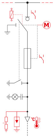
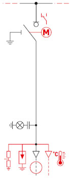
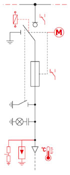
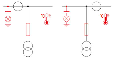
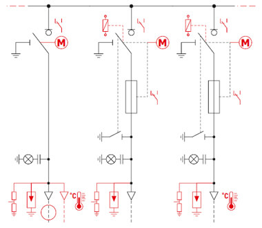
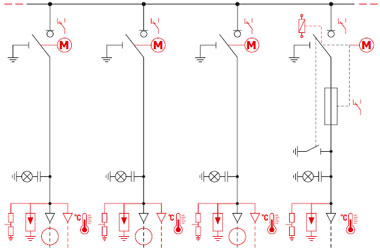
T-field equipment – disconnectors with fuses
| Podstawowe parametry | |
| Ur | 24 kV |
| fr | 50/60 Hz |
| Ud | 50/60 kV |
| Up | 125/145 kV |
| Ir | 250 A (125 A insert) |
| Ima | 5 kA (earthing conductor) |
| Itransfer | 1250 A |
| M2, E3 disconnector class | |
| M1, E2 earthing switch class | |
Optional equipment is marked in red on the wiring diagram.
Some optional equipment may be mutually exclusive or require the use of a deep cable compartment cover.
- compliance with PN-EN 62271-105 – AC fuse switchgear assemblies,
- compliance with PN-EN 62271-102, AC high-voltage disconnectors and earthing switches,
- T-field as a single module with an expansion option or can be combined with other configurations within a common tank in systems with up to four fields,
- three-position disconnector-earthing switch assembly, whose design is based on common moving contacts and separate fixed contacts of the earthing switch and disconnector,
- lower earthing switch ensuring earthing on both sides of the inserts,
- a disconnector equipped with a shunt current interruption system in a vacuum chamber during disconnection,
- a manual drive ensuring intuitive and easy manoeuvring and quick closing and opening of the switching equipment,
- synoptic display showing the status of devices and entire main circuits,
- storage drive function, which opens the disconnector contacts when MV inserts with thermal protection (blowout) or a release coil are used,
- insert burnout indicator,
- type A bushing insulators with plug-in socket, equipped with capacitive voltage dividers designed to work with voltage indicators in the LRM system,
- voltage presence indicator on the cable in the LRM system,
- pressure gauge - gas pressure indicator with a two-zone scale indicating the nominal absolute gas pressure (dry air) -250 kPa (0.25 MPa) at a temperature of 20°C (one per tank),
- a system of mechanical locks between the devices and the cable compartment cover, preventing incorrect connection operations - the cover can only be removed after the earthing switch has been closed,
- safety valve (one per tank), which opens as a result of pressure increase caused by an arc inside the tank, directing gases downwards into the cable duct,
- cable holders.
- 24V DC motor drive (other supply voltages available on request),
- pressure sensor (density meter) with auxiliary contacts – for cooperation with motor drive, telemechanics,
- auxiliary contacts as a representation of device statuses for telemechanics systems,
- fuse links equipped with a temperature limiter (thermal release) according to IEC 60282-1, DIN 43625,
- voltage sensors – low-power transformers,
- “ON” and “OFF” signalling in the form of indicator lights,
- anti-condensation heaters,
- C-type feed-through insulators with M16 thread equipped with capacitive voltage dividers designed to work with voltage indicators in the LRM system,
- possibility of expansion on the right and left sides,
- key lock for the disconnector or earthing switch socket,
- incremental trigger – DWN 24 V DC, 230V AC/DC coil (other voltages on request),
- AST-05 wireless temperature sensors, which are part of the eTemp system.
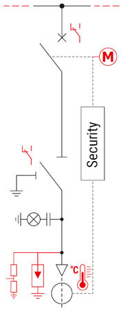
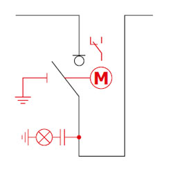
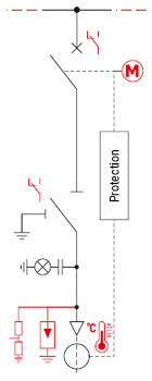
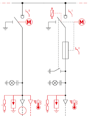
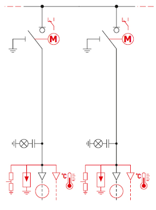
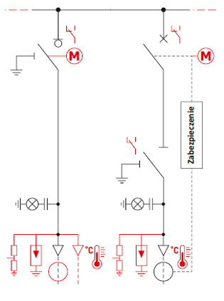
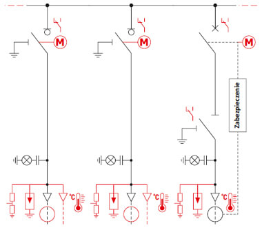
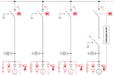
W field equipment – circuit breakers (power supply, outlet, transformer)
| Basic parameters | |
| Ur | 24 kV |
| fr | 50/60 Hz |
| Ud | 50/60 kV |
| Up | 125/145 kV |
| Ir | 630 A |
| Ik | up to 20 kA (1s) |
| Isc | up to 20 kA |
| Ief1 | up to 20 kA |
| Ima | up to 50 kA |
| Icc2 | 31,5 A |
| M2, E2, C2 disconnector class Switching range (O-0,3s-CO-15s-CO) |
|
| earthing switch class M1, E2 | |
Optional equipment is marked in red on the wiring diagram.
Some optional equipment may be mutually exclusive or require the use of a deep cable compartment cover.
- compliance with PN-EN 62271-100, High-voltage alternating current circuit breakers,
- compliance with PN-EN 62271-102, High-voltage alternating current disconnectors and earthing switches,
- W field as a single module with an expansion option or can be combined with other configurations within a common tank in systems with up to four fields,
- a circuit breaker assembly based on the use of vacuum chambers with a breaking current of 16kA or 20kA enclosed in a tank filled with dry air,
- a three-position disconnector-earthing switch assembly, whose design is based on common moving contacts and separate fixed contacts of the earthing switch and disconnector. The function of the disconnector is to ensure a safe break in the circuit,
- a manual spring drive for the circuit breaker, ensuring intuitive and easy manoeuvring as well as instantaneous closing and opening of the switching equipment; the drive has a circuit breaker arming system allowing for a fast on-off cycle,
- Manual drive of the three-position disconnector-earthing switch ensuring intuitive and easy manoeuvring of the switching equipment.
- Synoptic diagram showing the status of the devices and entire main circuits.
- circuit breaker arming signalling,
- autonomous protection, preferably AZZ-4 (manufactured by ITR) or WIC 1 (manufactured by SEG) with dedicated current transformers,
- C-type bushing insulators with M16 thread equipped with capacitive voltage dividers designed to work with voltage indicators in the LRM system and with electromagnetic locks,
- signal indicator of voltage presence on the cable in the LRM system,
- pressure gauge - gas pressure indicator with a two-zone scale indicating the nominal absolute gas pressure (dry air) -250 kPa (0.25 MPa) at a temperature of 20°C (one per tank),
- a system of mechanical locks between the devices and the cable compartment covers to prevent incorrect connection operations - the cover can only be removed after the earthing switch has been closed,
- safety valve (one per tank), which opens when the pressure inside the tank rises due to an arc, directing the gases downwards into the cable duct, thus eliminating the risk to personnel,
- cable voltage indicator,
- cable holders.
- 24V DC motor drive for the switch (other supply voltages available on request),
- pressure sensor (density meter) with auxiliary contacts – for cooperation with motor drive, telemechanics,
- auxiliary contacts as a representation of device states for telemechanics systems,
- safety devices other than the preferred autonomous ones, field controllers, SZR automation,
- voltage sensors - low-power transformers,
- current transformers, current sensors, Rogowski coils, earth fault transformers,
- auxiliary circuit cabinet/cooperation with telemechanics,
- ‘ON’ and ‘OFF’ signalling in the form of indicator lights,
- anti-condensation heaters,
- expansion possible on the right and left sides,
- surge arresters,
- AST-05 wireless temperature sensors, which are part of the eTemp system.
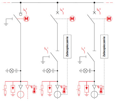
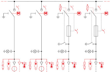
S-field equipment – disconnectors – couplers
| Basic parameters | |
| Ur | 24 kV |
| fr | 50/60 Hz |
| Ud | 50/60 kV |
| Up | 125/145 kV |
| Ir | 630 A |
| Ik | up to 20 kA (1s) |
| Ip | up to 50 kA |
| Ima | up to 50 kA |
| M2, E3 disconnector class | |
| M1, E2 earthing switch class | |
Optional equipment is marked in red on the wiring diagram.
Some optional equipment may be mutually exclusive or require the use of a deep cable compartment cover.
- compliance with PN-EN 62271-103, Disconnectors with rated voltage above 1kV up to and including 52kV,
- compliance with PN-EN 62271-102, High-voltage AC disconnectors and earthing switches,
- S field as a single module expandable to the right and left,
- disconnector based on common moving contacts and fixed contacts,
- arc extinguishing system during switching operations,
- manual drive ensuring intuitive and easy manoeuvring as well as quick closing and opening of switching equipment,
- synoptic display showing the status of devices and entire main circuits,
- pressure gauge - gas pressure indicator with a two-zone scale showing the nominal absolute pressure of the gas (dry air) -250 kPa (0.25 MPa) at a temperature of 20°C,
- safety valve (one per tank), which opens when the pressure inside the tank rises due to an arc, directing the gases downwards into the cable duct, thus eliminating the risk to personnel.
- 24V DC motor drive (other supply voltages available on request), easy to install on site,
- main track earthing switch for the right section,
- voltage presence indicator on the main tracks before and after the disconnector,
- pressure sensor (density meter) with auxiliary contacts - for cooperation with the motor drive, telemechanics,
- auxiliary contacts enabling the mapping of device statuses in telemechanics systems,
- key lock for the disconnector or earthing switch socket.
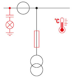
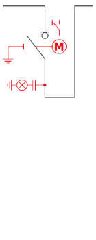
M-field equipment - measurement
| Basic parameters | |
| Ur | 24 kV |
| fr | 50/60 Hz |
| Ud | 50/60 kV |
| Up | 125/145 kV |
| Ir | 630 A |
| Ik | up to 20 kA (1s) |
| Ip | up to 50 kA |
Optional equipment is marked in red on the wiring diagram.
Some optional equipment may be mutually exclusive or require the use of a deep cable compartment cover.
- compliance with PN-EN 62271-200, AC switchgear in metal enclosures for rated voltages above 1 kV up to and including 52 kV,
- M840 field as a single module expandable to the right and left,
- busbar system enclosed in a stainless steel tank,
- set of voltage and current transformers,
- voltage presence indicator on main circuits,
- synoptic diagram with main circuit mapping,
- pressure gauge - gas pressure indicator with a two-zone scale indicating the nominal absolute pressure of the gas (dry air) -250 kPa (0.25 MPa) at a temperature of 20°C,
- safety valve (one per tank), which opens when the pressure inside the tank rises due to an arc, directing the gases downwards into the cable duct, thus eliminating the risk to personnel.
- anti-condensation heaters,
- AST-05 wireless temperature sensors, which are part of the eTemp system.
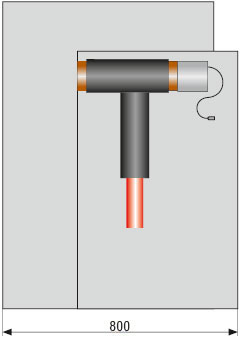
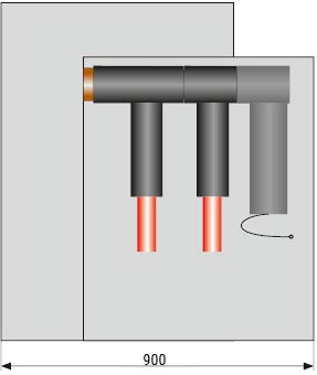
Method of constructing a cable duct under a TPM Air MV switchgear
The depth of the duct for dry cables should be selected taking into account the minimum bending radius specified in the technical specifications for the cable type, depending on its external diameter. An example of the recommended cable duct depth is shown in the illustration below. The use of a raised plinth or technical floor allows for the reduction or complete elimination of the need for a recessed channel.
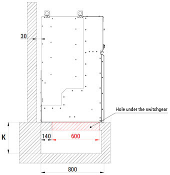
| Single core dry cable | ||
| cable cross-section (mm2) | bending radius (mm) | channel depth K (mm) |
| 50 | 370 | 400 |
| 70 | 400 | 430 |
| 95 | 440 | 470 |
| 120 | 470 | 500 |
| 150 | 500 | 550 |
| 185 | 540 | 600 |
| 240 | 590 | 700 |
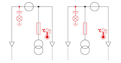
Connection options in the TPM Air switchgear – standard and deep cable cover

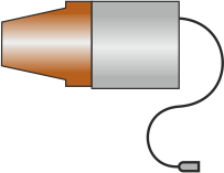
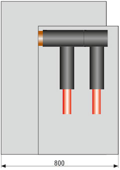
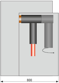
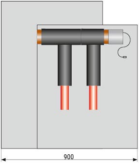
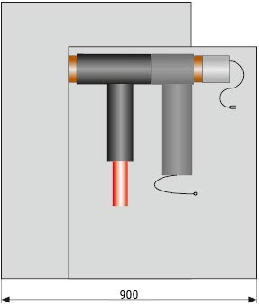
How to connect expandable sets
The TPM Air switchgear can be expanded with additional sets (provided that this has been discussed at the quotation and ordering stage). The connection methods are illustrated in the figures below. Detailed information can be found in the switchgear Technical and Operational Documentation.
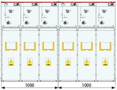
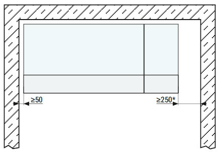
* Minimum space required to install an additional module.
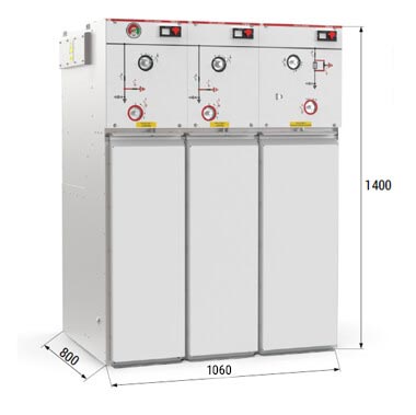
Typical configurations
Single fields
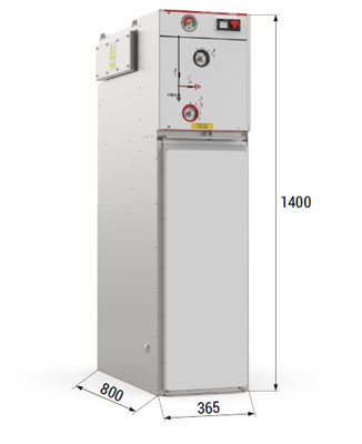
| Configuration | Width in mm | Depth in mm | Height in mm | |
| L | 360 | 800 | 900* | 1400 |
| T | 410 | 800 | 900* | 1400 |
| W | 510 | 800 | 900* | 1400 |
| S | 500 | 800 | 900* | 1400 |
* deepened cable compartment cover
Optional equipment is marked in red on the wiring diagram.
Some optional equipment may be mutually exclusive or require the use of a deep cable compartment cover.

Optional equipment is marked in red on the wiring diagram.
Some optional equipment may be mutually exclusive or require the use of a deep cable compartment cover.
Two-pole system
| Configuration | Width in mm | Depth. in mm | Height in mm | |
| LL | 680 | 800 | 900* | 1400 |
| LT | 740 | 800 | 900* | 1400 |
| LW | 815 | 800 | 900* | 1400 |
* deepened cable compartment cover
Optional equipment is marked in red on the wiring diagram.
Some optional equipment may be mutually exclusive or require the use of a deep cable compartment cover.
Three-pole system
| Configuration | Width in mm | Depth. in mm | Height in mm | |
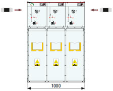
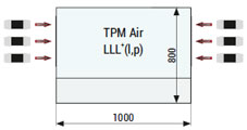
| LLL | 1000 | 800 | 900* | 1400 |
| LLT | 1060 | 800 | 900* | 1400 |
| LLW | 1135 | 800 | 900* | 1400 |
* deepened cable compartment cover
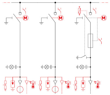
Optional equipment is marked in red on the wiring diagram.
Some optional equipment may be mutually exclusive or require the use of a deep cable compartment cover.
| Configuration | Width in mm | Depth in mm | Height in mm | |
| LTT | 1100 | 800 | 900* | 1400 |
| LWW | 1200 | 800 | 900* | 1400 |
* deepened cable compartment cover
Optional equipment is marked in red on the wiring diagram.
Some optional equipment may be mutually exclusive or require the use of a deep cable compartment cover.
Four-pole circuit
| Configuration | Width in mm | Depth. in mm | Height in mm | |
| LLLL | 1320 | 800 | 900* | 1400 |
| LLLT | 1380 | 800 | 900* | 1400 |
| LLLW | 1455 | 800 | 900* | 1400 |
| LLTT | 1440 | 800 | 900* | 1400 |
| LLWW | 1520 | 800 | 900* | 1400 |
Optional equipment is marked in red on the wiring diagram.
Some optional equipment may be mutually exclusive or require the use of a deep cable compartment cover.