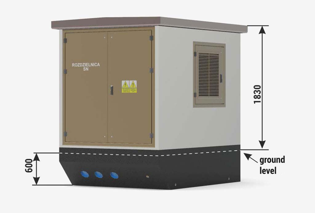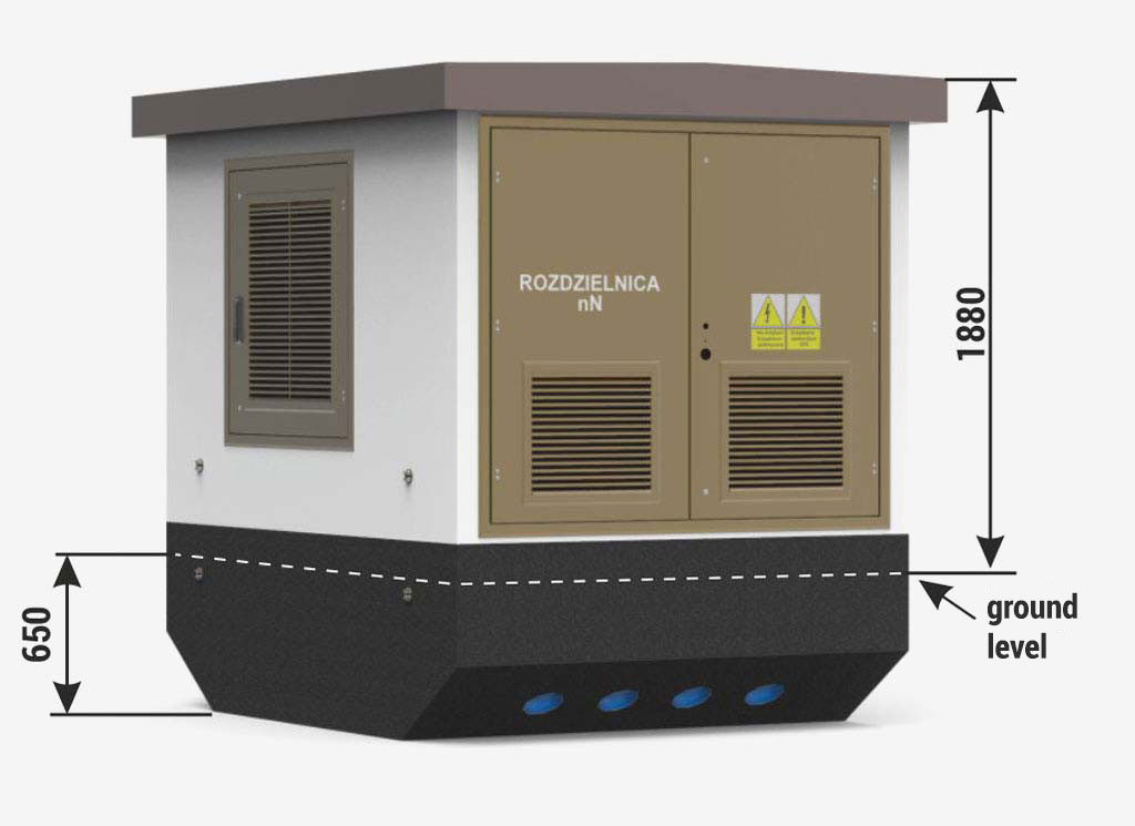
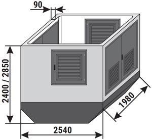
Stacja typu Mzb2 (2,54x1,98) 20/630
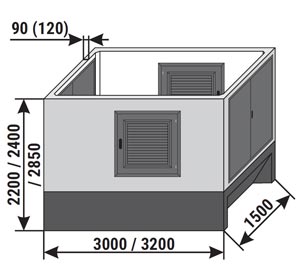
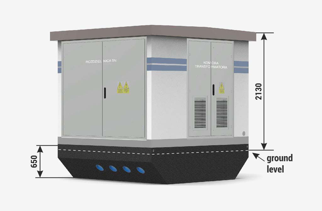
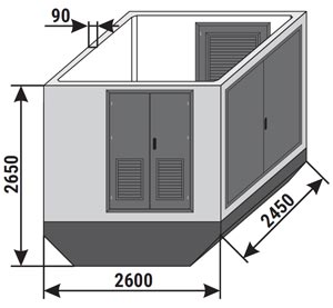
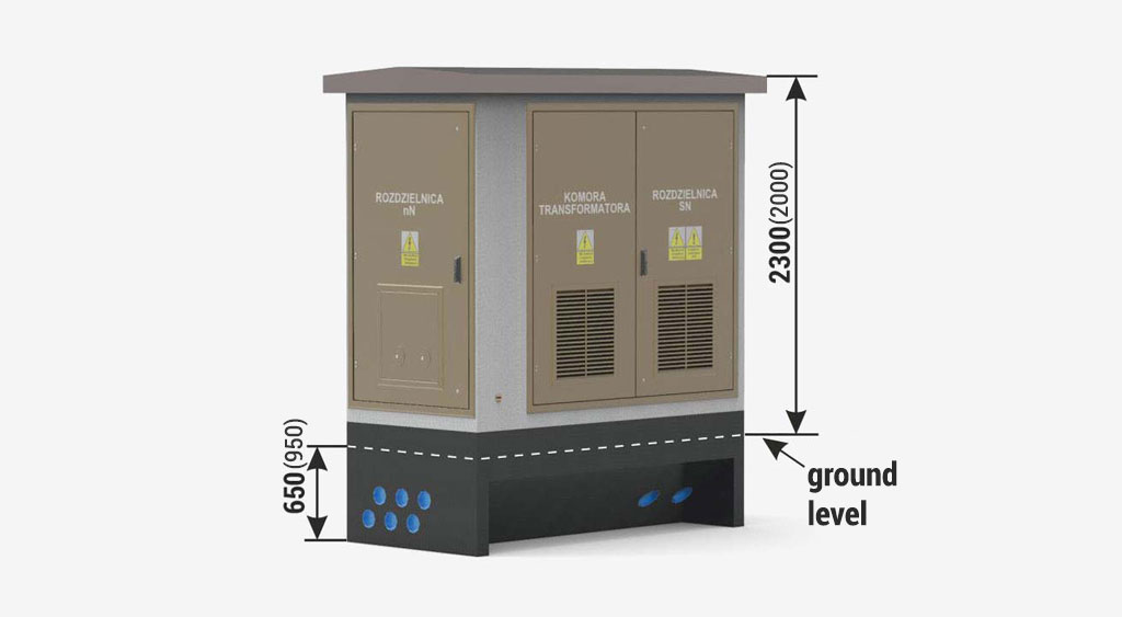
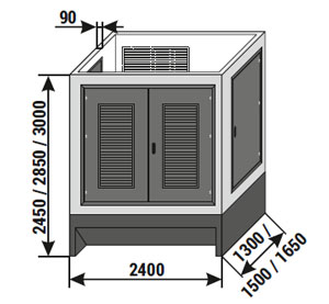
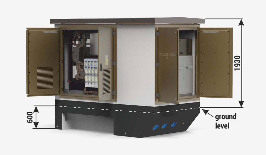
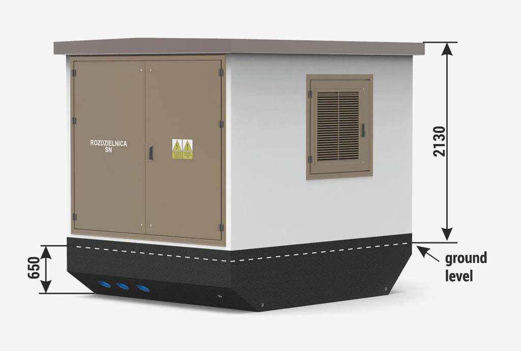
Height of the main structure of the substation:
Standard 2400 mm
Optional 2850 mm

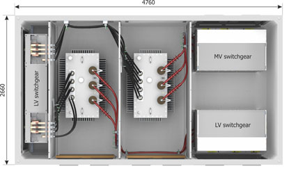
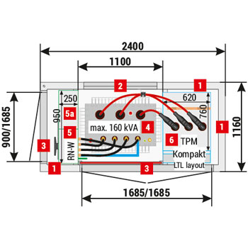
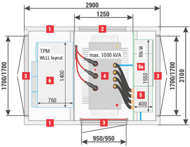
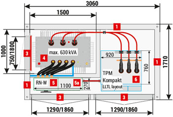
Placement of equipment

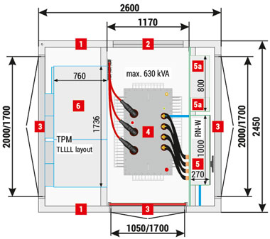
Mzb2 (2,54x1,98) 20/630-4"a” (Minibox 20/630)
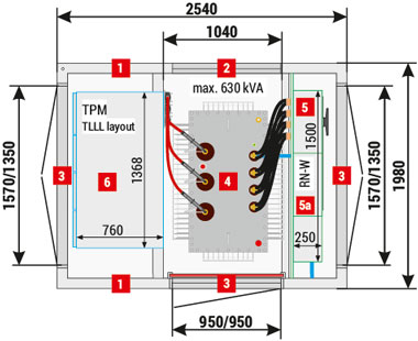
Mzb2 (2,54x1,98) 20/630-4”a” (dotychczas Minibox 20/630)
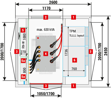
Mzb2 (2,54x1,98) 20/630-4"b” (Minibox 20/630)
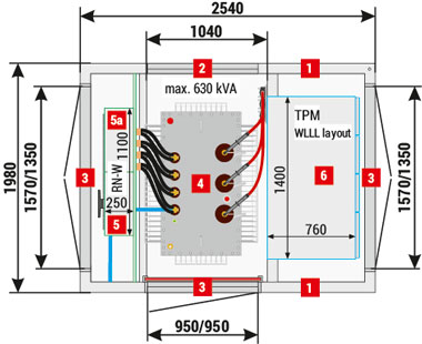
Mzb2 (2,54x1,98) 20/630-4”b” (dotychczas Minibox 20/630)
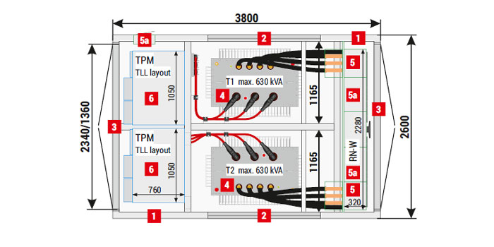
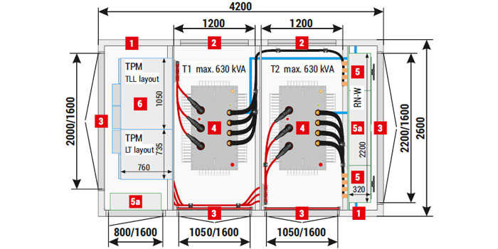
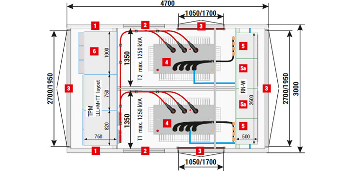
1 Walls, 90 mm thick - standard
2 Ventilation louvres IP 23D - standard, IP 43 - optional
3 Doors: solid or with ventilation louvres, IP 23D - standard, IP 43 - optional
4 Transformer
5 LV switchgear
5a AMI cabinet / Smart Grid / telemetry / auxiliary
6 MV switchgear

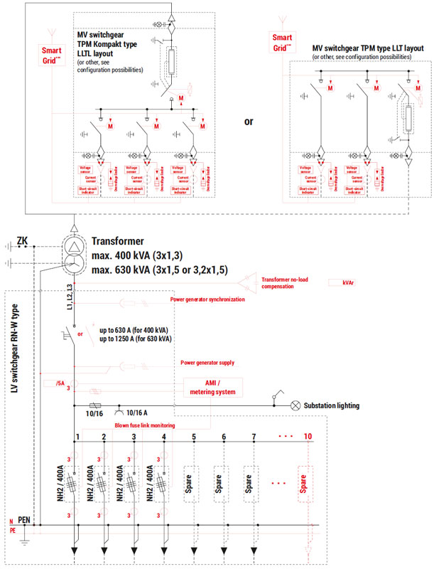
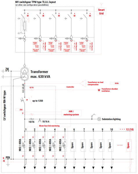
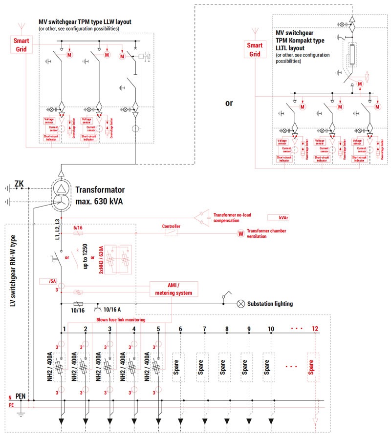
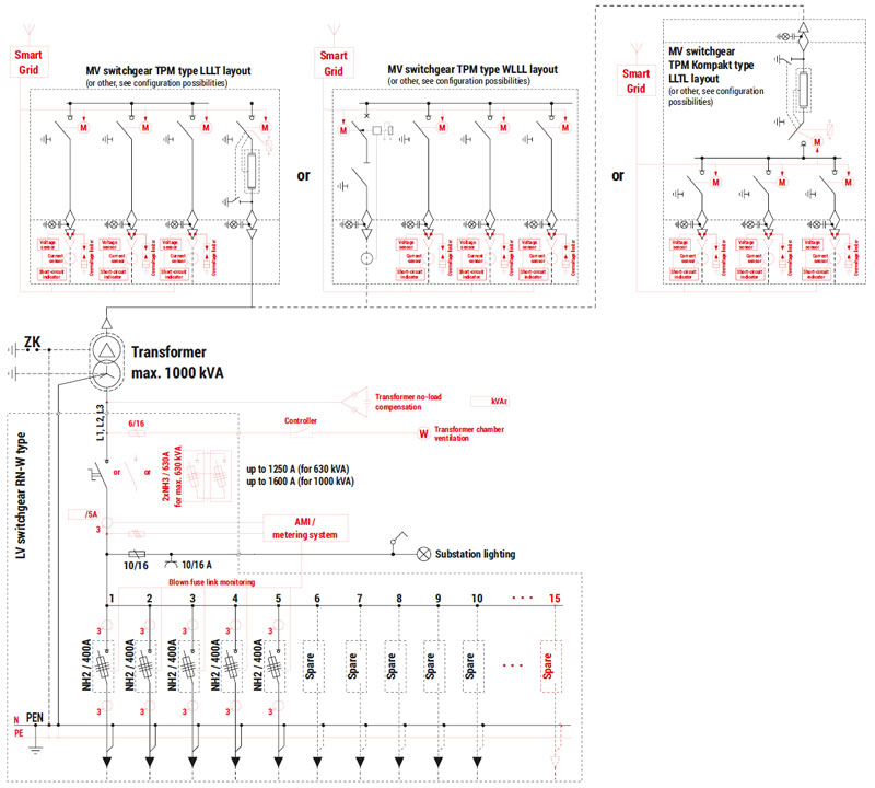
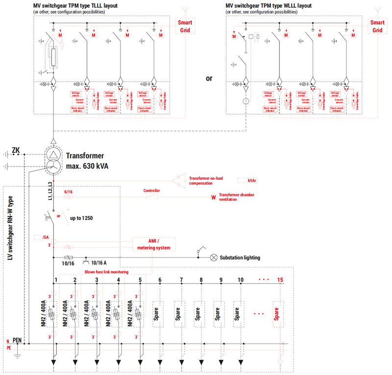
Electrical diagram

Schemat elektryczny stacji Mzb2 (2,54x1,98) 20/630 (dotychczas Minibox 20/630)

Optional equipment was marked with red on the electrical diagram.

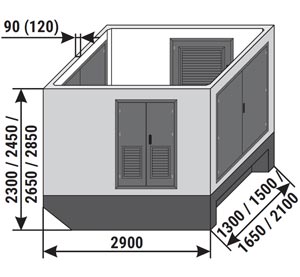
Technical parameters / configuration possibilities
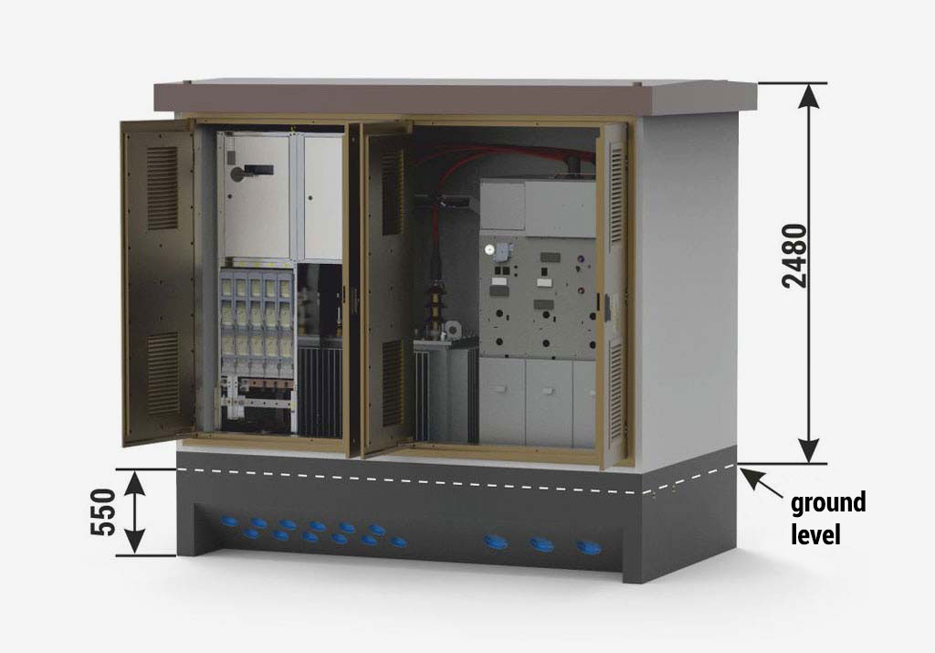
Obudowy betonowe Mzb2
Masa / Powierzchnia
bryła główna: 4 800 kg
dach betonowy: 1 800 kg
dach metalowy: 300 kg
powierzchnia użytkowa: 4,15 m2
Technical parameters / configuration possibilities
Transformer* (4) Maximum power / dimension 630 kVA / 980 x 1550 x 1850 [mm]
Internal arc resistance classification IAC-AB-20 kA-1s
Enclosure class 20
Electrical parameters of switchgears MV LV
Rated voltage up to 25 kV up to 0,69 kV
Rated current 630 A up to 1250 A
Rated short-time withstand current up to 25 kA (1s) up to 25 kA (1s)
Rated peak withstand current up to 63 kA up to 55 kA
Switchgear** Type Maximum number of bays
LV (5) RN-W 15
MV (6) TPM 4 (TLLL or WLLL)

* Transformer inserted from above, before the roof is attached.

** Detailed selection of switchgears and their equipment is listed in chapters dedicated to individual devices in the catalogue. Example layouts of switchgears and corresponding substation configurations are specified in parentheses. The possibility of installing other types and configurations of switchgears should be arranged every time with the substation manufacturer.

Stacja typu Mzb1 20/630
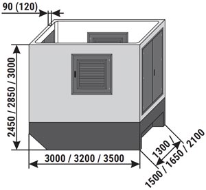
Height of the main structure of the substation:
Standard 2850 mm

Placement of equipment

Mzb1 20/630-4"a”
Mzb1 20/630-4”a”
Mzb1 20/630-3"b”
Mzb1 20/630-3”b”
Mzb1 20/630-1"b”
Mzb1 20/630-1”b”
1 Walls, 120 mm thick - standard, 90 mm thick - optional
Walls without holes - REI 120 fire integrity class
2 Ventilation louvres IP 23D - standard, IP 43 - optional
In ventilation louvres mounted in walls with fire integrity class,
fire dampers are installed (e.g. EI 60 or EIS 120) - optional
3 Doors: solid or with ventilation louvres, IP 23D - standard, IP 43 - optional
Doors with fire resistance e.g EI 60 or EI 120 - optional
4 Transformer
5 LV switchgear
5a AMI cabinet / SMART GRID / telemetry / auxiliary
6 MV switchgear

Electrical diagram

Schemat elektryczny stacji Mzb1 20/630

Optional equipment was marked with red on the electrical diagram.

Technical parameters / configuration possibilities

Obudowy betonowe Mzb1
Mass / area 3,06x1,71 (3x1,65)
Main structure 9 000 (8 000) kg
Concrete roof 2 000 kg
Usable area 4,06 m2
Technical parameters / configuration possibilities
Transformer* (4) Maximum power / dimension 630 kVA / 950 x 1550 x 1850 [mm]
Internal arc resistance classification IAC-AB-20 kA-1s
Enclosure class 10
Electrical parameters of switchgears MV LV
Rated voltage up to 25 kV up to 0,69 kV
Rated current 630 A up to 1250 A
Rated short-time withstand current up to 25 kA (1s) up to 25 kA (1s)
Rated peak withstand current up to 63 kA up to 55 kA
Switchgear** Type Maximum number of bays
LV (5) RN-W 12
MV (6) Rotoblok (1000 mm) 1 (possibility only in „b” version)
TPM / TPM Kompakt 3 (TLL or WLL) / 4 (LLTL)

* Transformer inserted from above, before the roof is attached.

** Detailed selection of switchgears and their equipment is listed in chapters dedicated to individual devices in the catalogue. Example layouts of switchgears and corresponding substation configurations are specified in parentheses. The possibility of installing other types and configurations of switchgears should be arranged every time with the substation manufacturer.
Stacja typu Mzb2 20/630
Height of the main structure of the substation:
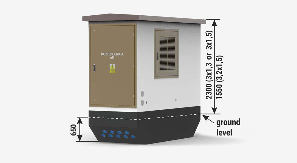
Standard 2850 mm (3x1,3 lub 3x 1,5)
2200 mm (3,2x1,5)

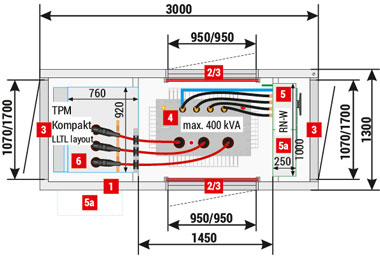
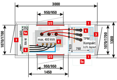
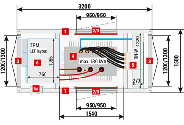
Placement of equipment

Mzb2 (3x1,3) 20/400-4"a”
Mzb2 (3x1,3) 20/400-4”a”
Mzb2 (3x1,3) 20/400-4"b”
Mzb2 (3x1,3) 20/400-4”b”
Mzb2 (3,2x1,5) 20/630-3"a”
Mzb2 (3,2x1,5) 20/630-3”a”
Mzb2 (3x1,5) 20/630-4"b”
Mzb2 (3x1,5) 20/630-4”b”
1 Walls, 90 mm thick - standard
2 Ventilation louvres IP 23D - standard, IP 43 - optional
3 Doors: solid or with ventilation louvres, IP 23D - standard, IP 43 - optional
4 Transformer
5 LV switchgear
5a AMI cabinet / Smart Grid / telemetry / auxiliary
6 MV switchgear

Electrical diagram

Schemat elektryczny stacji Mzb2 20/630

Optional equipment was marked with red on the electrical diagram.

Technical parameters / configuration possibilities

Obudowy betonowe Mzb2
Mass / area 3x1,3 (3,2x1,5)
Main structure 6 000 (7 000) kg
Concrete roof 1 100 (1 400) kg
Usable area 3,16 (3,99) m2
Mass / area 3x1,5 (3,06x1,56)
Main structure 6 500 (8 500) kg
Concrete roof 1 300 kg
Usable area 3,72 m2
Technical parameters / configuration possibilities
Transformer* (4) Maximum power / dimension 400 kVA / 900 x 1350 x 1700 [mm]
(for width 1300)
630 kVA / 980 x 1400 x 1750 [mm]
Internal arc resistance classification IAC-AB-16 kA-1s
Enclosure class up to 10 (depending on configuration)
Electrical parameters of switchgears MV LV
Rated voltage up to 25 kV up to 0,69 kV
Rated current 630 A up to 1250 A
Rated short-time withstand current up to 25 kA (1s) up to 25 kA (1s)
Rated peak withstand current up to 63 kA up to 55 kA
Switchgear** Type Maximum number of bays
LV (5) RN-W 7 (3x1,3) / 10 (3x1,5 or 3,2x1,5)
MV (6) TPM 3 (LLT or LLW - for 3x1,5 or 3,2x1,5)
TPM Kompakt 4 (LLTL)

* Transformer inserted from above, before the roof is attached.

** Detailed selection of switchgears and their equipment is listed in chapters dedicated to individual devices in the catalogue. Example layouts of switchgears and corresponding substation configurations are specified in parentheses. The possibility of installing other types and configurations of switchgears should be arranged every time with the substation manufacturer.

*** Smart Grid cabinet fitted outside.

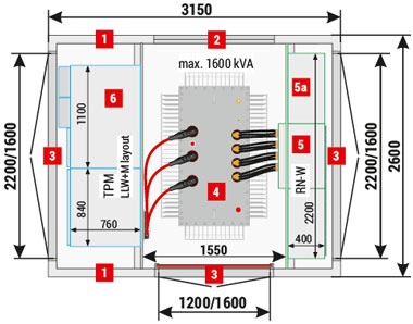
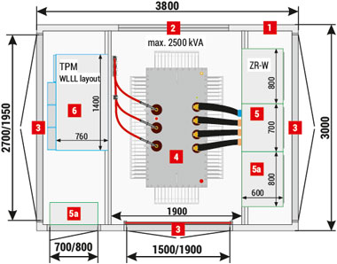
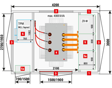
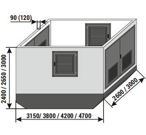
Stacja typu Mzb2 (3,15x2,6 do 4,76x3,06) - warianty jednotransformatorowe
Height of the main structure of the substation:
Standard 2650 mm
Optional 2400, 3000 mm
Substations may be made in variants:
Length 3150 mm / 3800 mm / 4200 mm / 4700 mm
Width 2600 mm / 3000 mm
Above dimensions are valid for 90 mm thick walls. For 120 mm walls, for every dimensions 60 mm should be added.

Placement of equipment

Mzb2 (3,15x2,6) 20/1600-4
Mzb2 (3,8x3) 20/2500-4
Mzb2 (4,2x3) 20/4000-3
1 Walls, 120 mm thick - standard, 90 mm - optional
2 Ventilation louvres IP 23D - standard, IP 43 - optional
3 Doors: solid or with ventilation louvres, IP 23D - standard, IP 43 - optional
4 Transformer
5 LV switchgear
5a AMI cabinet / Smart Grid / telemetry / auxiliary
6 MV switchgear

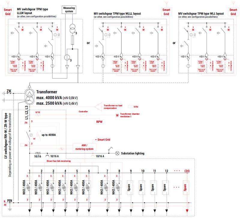
Electrical diagram

Schemat elektryczny stacji Stacja typu Mzb2 (3,15x2,6 do 4,76x3,06) - warianty jednotransformatorowe

Optional equipment was marked with red on the electrical diagram.

Technical parameters / configuration possibilities

Obudowy betonowe Mzb2
Mass (without transformer) / Area
Main structure 9 500 - 22 000 kg
Concrete roof 3 200 - 5 200 kg
Metal roof 350 - 800 kg
Usable area 7,19 - 12,75 m2
Technical parameters / configuration possibilities
Transformer* (4) Maximum power / dimension 4000 kVA (nN 0,8 kV)
2500 kVA (nN 0,4 kV)
Internal arc resistance classification IAC-AB-20 kA-1s
Enclosure class up to 10 (depending on configuration)
Electrical parameters of switchgears MV LV
Rated voltage up to 25 kV up to 0,8 kV
Rated current 630 A up to 4000 A
Rated short-time withstand current up to 25 kA (1s) up to 85 kA (1s)
Rated peak withstand current up to 63 kA up to 187 kA
Switchgear** Type Maximum number of bays
LV (5) RN-W 20 (width 2600) / 24 (width 3000)
ZR-W 16 (width 2600) / 20 (width 3000)
MV (6) TPM 6 (e.g. LLLLLW for width 2600)
7 (e.g. TLLLLLL for width 3000)
Rotoblok SF (500) 4 (width 2600) / 5 (width 3000)

* Transformer inserted from above, before the roof is attached.

** SDetailed selection of switchgears and their equipment is listed in chapters dedicated to individual devices in the catalogue. Example layouts of switchgears and corresponding substation configurations are specified in parentheses. The possibility of installing other types and configurations of switchgears should be arranged every time with the substation manufacturer.
Stacja typu Mzb2”b” 20/630
Height of the main structure of the substation:
Standard 2650 mm

Placement of equipment

Mzb2"b” 20/630-5"a”
Mzb2”b” 20/630-5”a”
Mzb2"b” 20/630-5"b”
Mzb2”b” 20/630-5”b”
1 Walls, 90 mm thick - standard
2 Ventilation louvres IP 23D - standard, IP 43 - optional
3 Doors: solid or with ventilation louvres, IP 23D - standard, IP 43 - optional
4 Transformer
5 LV switchgear
5a AMI cabinet / Smart Grid / telemetry / auxiliary
6 MV switchgear

Electrical diagram

Schemat elektryczny stacji Stacja typu Mzb2”b” 20/630

Optional equipment was marked with red on the electrical diagram.

Technical parameters / configuration possibilities

Obudowy betonowe Mzb2
Mass / area
Main structure 8000 kg
Concrete roof 2 450 kg
Metal roof 300 - 500 kg
Usable area 5,49 m2
Technical parameters / configuration possibilities
Transformer* (4) Maximum power / dimension 630 kVA / 980 x 1550 x 1850 [mm]
Internal arc resistance classification IAC-AB-20 kA-1s
Enclosure class 10
Electrical parameters of switchgears MV LV
Rated voltage up to 25 kV up to 0,69 kV
Rated current 630 A up to 1250 A
Rated short-time withstand current up to 25 kA (1s) up to 25 kA (1s)
Rated peak withstand current up to 63 kA up to 55 kA
Switchgear** Type Maximum number of bays
LV (5) RN-W 12 (18 if Smart Grid with AMI)
MV (6) TPM 5 (TLLLL or WLLLL)

* Transformer inserted from above, before the roof is attached.

** Detailed selection of switchgears and their equipment is listed in chapters dedicated to individual devices in the catalogue. Example layouts of switchgears and corresponding substation configurations are specified in parentheses. The possibility of installing other types and configurations of switchgears should be arranged every time with the substation manufacturer.
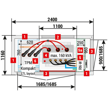
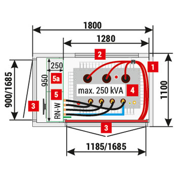
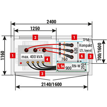
Stacja typu Mzb1 20/160
Height of the main structure of the substation:
Standard 2850 mm

Placement of equipment

Mzb1 (2,4x1,16) 20/160-3"a”
Mzb1 (2,4x1,16) 20/160-3”a”
Mzb1 (2,4x1,16) 20/160-3"b”
Mzb1 (2,4x1,16) 20/160-3”b”
Mzb1 (1,8x1,1) 20/250 version without MV switchgear
Mzb2 (2,4x1,16) 20/400-3”a”
1 Walls
90 mm thick - standard for 2,4x2,16 substation
60 mm thick - standard for 1,8x1,1 substation
2 Ventilation louvres IP 23D - standard, IP 43 - optional
3 Doors: solid or with ventilation louvres, IP 23D - standard, IP 43 - optional
4 Transformer
5 LV switchgear
5a AMI cabinet / Smart Grid / telemetry / auxiliary
6 MV switchgear

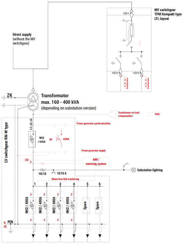
Electrical diagram

Schemat elektryczny stacji Mzb1 20/160

Optional equipment was marked with red on the electrical diagram.

Technical parameters / configuration possibilities

Obudowy betonowe Mzb1
Usable area 2,4x1,16 1,8x1,1
Main structure 4 200 kg 3 800 kg
Concrete roof 1 000 kg 600 kg
Usable area 2,18 m2 1,65 m2
Technical parameters / configuration possibilities
Transformer* (4) Maximum power / dimension do 160 kVA / 800 x 1050 x 1500 [mm]
do 400 kVA / 900 x 1150 x 1600 [mm]
(depending on substation type)
Internal arc resistance classification IAC-AB-16 kA-1s
Enclosure class up to 10 (depending on configuration)
Electrical parameters of switchgears MV LV
Rated voltage up to 25 kV up to 0,69 kV
Rated current 630 A up to 630 A
Rated short-time withstand current up to 20 kA (1s) up to 20 kA (1s)
Rated peak withstand current up to 50 kA up to 40 kA
Switchgear** Type Maximum number of bays
LV (5) RN-W 6
MV (6) TPM Kompakt / NONE 3 (LTL) / without MV switchgear

* Transformer inserted from above, before the roof is attached.

** Detailed selection of switchgears and their equipment is listed in chapters dedicated to individual devices in the catalogue. Example layouts of switchgears and corresponding substation configurations are specified in parentheses. The possibility of installing other types and configurations of switchgears should be arranged every time with the substation manufacturer.
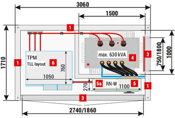
Stacja typu Mzb2 (3x1,65) 20/630
Height of the main structure of the substation:
Standard 2400 mm
Optional 2250 mm / 2850 mm

Placement of equipment

Mzb2 (3x1,65) 20/630-3"a”
Mzb2 (3x1,65) 20/630-3”a”
Mzb2 (3x1,65) 20/630-4"b”
Mzb2 (3x1,65) 20/630-4”b”
1 Walls, 120 mm thick - standard, 90 mm thick - optional
2 Ventilation louvres IP 23D - standard, IP 43 - optional
3 Doors: solid or with ventilation louvres, IP 23D - standard, IP 43 - optional
4 Transformer
5 LV switchgear
5a AMI cabinet / Smart Grid / telemetry / auxiliary
6 MV switchgear

Electrical diagram

Schemat elektryczny stacji Mzb2 (3x1,65) 20/630

Optional equipment was marked with red on the electrical diagram.

Technical parameters / configuration possibilities

Obudowy betonowe Mzb2
Mass / area 3x1,65 (3,06x1,71)
Main structure 7 000 (8 500) kg
Concrete roof 2 000 kg
Usable area 4,06 m2
Technical parameters / configuration possibilities
Transformer* (4) Maximum power / dimension 630 kVA / 980 x 1550 x 1750 [mm]
Internal arc resistance classification IAC-AB-20 kA-1s
Enclosure class up to 10 (depending on configuration)
Electrical parameters of switchgears MV LV
Rated voltage up to 25 kV up to 0,69 kV
Rated current 630 A up to 1250 A
Rated short-time withstand current up to 25 kA (1s) up to 25 kA (1s)
Rated peak withstand current up to 63 kA up to 55 kA
Switchgear** Type Maximum number of bays
LV (5) RN-W 12
MV (6) TPM 3 (e.g. WLL or LLT)
TPM Kompakt (obly for h=2850) 4 (LLTL)

* Transformer inserted from above, before the roof is attached.

** Detailed selection of switchgears and their equipment is listed in chapters dedicated to individual devices in the catalogue. Example layouts of switchgears and corresponding substation configurations are specified in parentheses. The possibility of installing other types and configurations of switchgears should be arranged every time with the substation manufacturer.
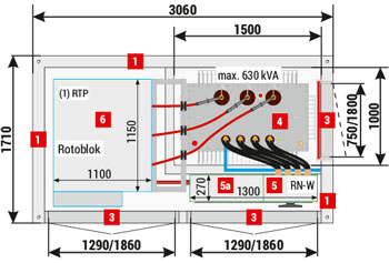
Stacja typu Mzb2 20/630 (1000)
Height of the main structure of the substation:
Standard 2300 mm
Optional 2650 mm / 2850 mm

Placement of equipment

Mzb2 (2,9x2,1) 20/630-4"a”
Mzb2 (2,9x2,1) 20/630-4”a”
Mzb2 (2,9x2,1) 20/630-4"b”
Mzb2 (2,9x2,1) 20/630-4”b”
Mzb2 (2,9x2,1) 20/1000-4"a”
Mzb2 (2,9x2,1) 20/1000-4”a”
1 Walls, 90 mm thick - standard
2 Ventilation louvres IP 23D - standard, IP 43 - optional
3 Doors: solid or with ventilation louvres, IP 23D - standard, IP 43 - optional
4 Transformer
5 LV switchgear
5a AMI cabinet / Smart Grid / telemetry / auxiliary
6 MV switchgear

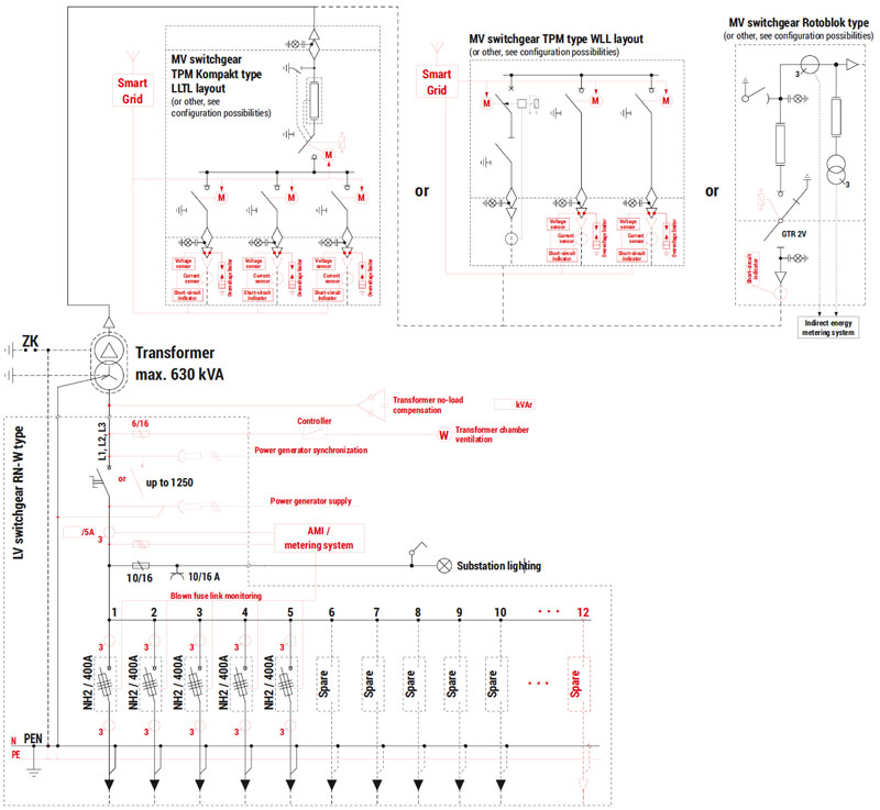
Electrical diagram

Schemat elektryczny stacji Mzb2 20/630 (1000)

Optional equipment was marked with red on the electrical diagram.

Technical parameters / configuration possibilities

Obudowy betonowe Mzb2
Mass / area 2,9x2,1x2,3 (2,9x2,1x2,85)
Main structure 7 500 (8 600) kg
Concrete roof 2 200 kg
Metal roof 400 kg
Usable area 5,22 m2
Technical parameters / configuration possibilities
Transformer* (4) Maximum power / dimension 1000 kVA / 1150 x 1750 x 1850 [mm]
Internal arc resistance classification IAC-AB-20 kA-1s
Enclosure class up to 10 (depending on configuration)
Electrical parameters of switchgears MV LV
Rated voltage up to 25 kV up to 0,8 kV
Rated current 630 A up to 1600 A
Rated short-time withstand current up to 25 kA (1s) up to 35 kA (1s)
Rated peak withstand current up to 63 kA up to 77 kA
Switchgear** Type Maximum number of bays
LV (5) RN-W 12 (for h = 2300) / 15 (for h = 2850)
MV (6) TPM 4 (WLLL or LLLT)
TPM Kompakt (only for h=2850) 4 (LLTL)

* Transformer inserted from above, before the roof is attached.

** Detailed selection of switchgears and their equipment is listed in chapters dedicated to individual devices in the catalogue. Example layouts of switchgears and corresponding substation configurations are specified in parentheses. The possibility of installing other types and configurations of switchgears should be arranged every time with the substation manufacturer.
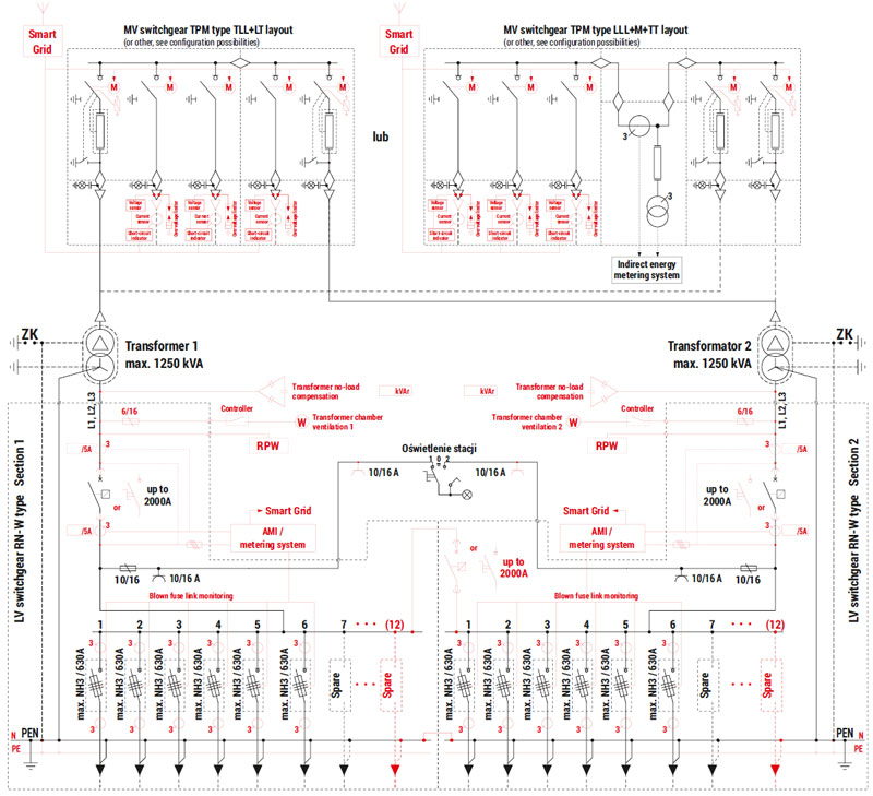
Stacja typu Mzb2 (3,15x2,6 do 4,76x3,06) - warianty dwutransformatorowe
Height of the main structure of the substation:
Standard 2650 mm
Optional 2400, 3000 mm
Substations may be made in variants:
Length 3150 mm / 3800 mm / 4200 mm / 4700 mm
Width 2600 mm / 3000 mm

Placement of equipment

Mzb2 (3,8x2,6) 20/2x630-6
Mzb2 (4,2x2,6) 20/2x630-5
Mzb2 (4,7x3) 20/2x1250-6
1 Walls, 120 mm thick - standard, 90 mm - optional
2 Ventilation louvres IP 23D - standard, IP 43 - optional
3 Doors: solid or with ventilation louvres, IP 23D - standard, IP 43 - optional
4 Transformer
5 LV switchgear
5a AMI cabinet / Smart Grid / telemetry / auxiliary
6 MV switchgear

Electrical diagram

Schemat elektryczny stacji Stacja typu Mzb2 (3,15x2,6 do 4,76x3,06) - warianty dwutransformatorowe

Optional equipment was marked with red on the electrical diagram.

Technical parameters / configuration possibilities

Obudowy betonowe Mzb2
Mass (without transformer) / Area
Main structure 9 500 - 22 000 kg
Concrete roof 3 200 - 5 200 kg
Metal roof 350 - 800 kg
Usable area 7,19 - 12,75 m2
Technical parameters / configuration possibilities
Transformer* (4) Maximum power / dimension 2 x do 1250 kVA
Internal arc resistance classification IAC-AB-20 kA-1s
Enclosure class up to 10 (depending on configuration)
Electrical parameters of switchgears MV LV
Rated voltage up to 25 kV up to 0,8 kV
Rated current 630 A up to 2 000 A
Rated short-time withstand current up to 25 kA (1s) up to 35 kA (1s)
Rated peak withstand current up to 63 kA up to 77 kA
Switchgear** Type Maximum number of bays
LV (5) RN-W up to 2 x 12
MV (6) TPM 6 (e.g. TLL; TLL or LLL+M+TT)
Rotoblok SF (500) 5

* Transformer inserted from above, before the roof is attached.

** Detailed selection of switchgears and their equipment is listed in chapters dedicated to individual devices in the catalogue. Example layouts of switchgears and corresponding substation configurations are specified in parentheses. The possibility of installing other types and configurations of switchgears should be arranged every time with the substation manufacturer.
Additional information