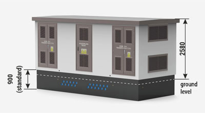
| External/internal height of the main structure of the substation: | |
| Standard | 2350 mm / 2150 mm |
| Optional | 2650 mm / 2450 mm or 3000 mm / 2800 mm |
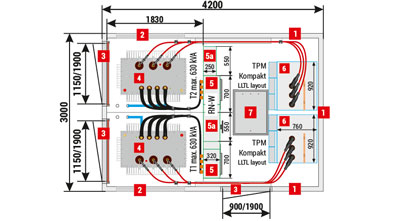
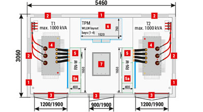
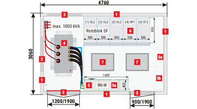
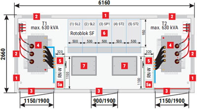
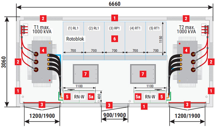
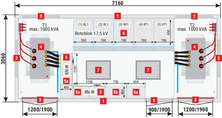
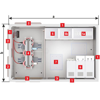
Placement of equipment
MRw-b(pp) (4,26x2,66) 22/2x630-8
MRw-b(pp) (5,46x3,06) 20/2x1000-4
MRw-b(pp) (4,76x3,06) 20/1000-5
MRw-b(pp) (6,16x2,66) 20/2x630-5
MRw-b(pp) (6,66x3,06) 20/2x1000-5
MRw-b(pp) (7,16x3,06) 20/2x1000-5
MRw-b(pp) (8,16x3,06) 20/2x1000-7
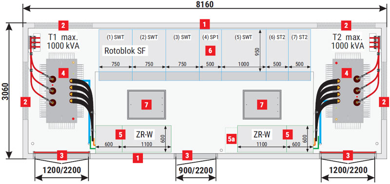
| 1 | Walls, 120 mm thick - standard, 90 mm - optional Solid walls - REI 120 fire integrity class |
| 2 | Ventilation louvres IP 23D - standard, IP 43 - optional In ventilation louvres mounted in walls with fire integrity class, fire dampers are installed (e.g. EI 60 or EIS 120) - optional |
| 3 | Doors: solid or with ventilation louvres, without fire integrity class IP 23D - standard, IP 43 - optional Doors with fire resistance e.g EI 60 or EI 120 - optional |
| 4 | Transformer |
| 5 | LV switchgear |
| 5a | AMI cabinet / Smart Grid / telemetry / auxiliary |
| 5b | Capacitor bank |
| 6 | MV switchgear |
| 7 | Cable duct hatch door |
Possibility of constructing enclosures
MRw-bpp (5,46x3,06) 20/2000-3
| Dimensions of concrete enclosures | ||||||
| b - Width [mm] | ||||||
| a - Length [mm] | 2410 | 2510 | 2660 | 3060 | 3560 | |
| 4260 | + | + | + | + | ||
| 4760 | + | + | + | + | ||
| 4760 | + | |||||
| 5460 | + | + | + | + | ||
| 5460 | + | |||||
| 6160 | + | + | + | |||
| 6660 | + | + | + | |||
| 7160 | + | + | + | |||
| 8160 | + | + | + | |||
| Wall thick [mm] |
90/120* | 90/120* | 90/120* | 90/120* | 120 | |
| Technical parameters** | ||
| Transformer (4) Maximum power / dimension | 4000 kVA or multiple | |
| Internal arc resistance classification | do IAC-AB-25 kA-1s | |
| Enclosure class | up to 10 (depending on substation configuration) | |
| Electrical parameters of switchgears | MV | LV |
| Rated voltage | up to 36 kV | up to 1 kV |
| Rated current | up to 4000 A | up to 6300 A |
| Rated short-time withstand current | up to 40 kA (3s) | up to 105 kA (1s) |
| Rated peak withstand current | up to 100 kA | up to 231 kA |
| Configuration of MV and LV switchgears*** | ||
* Table specifies enclosures with wall thickness of 120 mm. In case of enclosures with a wall thickness of 90 mm, subtract 60 mm from the external dimensions of the enclosure.
** Technical parameters are specified as maximum, they will depend on the configuration of the substation and on devices used.
*** Detailed selection of switchgears and their equipment is listed in chapters dedicated to individual devices in the catalogue.