Due to the design and dimensions - the height above the ground level is only 1700 mm and the low weight - including the ~ 8T transformer, a station dedicated to large-scale photovoltaic installations - installation between the tables with panels. The station is mounted on a concrete foundation and can be transported as a whole, including the transformer.
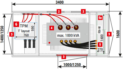
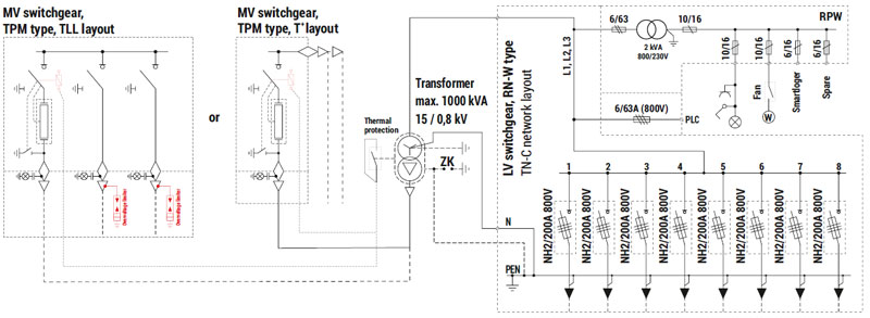
MRw (3,4x1,6) 20/1000-1(3)

| 1 | Substation placement part — concrete foundation |
| 2 | Ventilation louvres IP 23D - standard, IP 43 - optional |
| 3 | Doors: solid or with ventilation louvres IP 23D - standard, IP 43 - optional |
| 4 | Transformer |
| 5 | LV switchgear |
| 5a | AMI cabinet / telemetry / auxiliary |
| 6 | MV switchgear |
Note!
The catalogue presents example substation configurations.
| Mass / Area | |
| Concrete foundation | 3 000 kg |
| Metal main structure | 1 500 kg |
| Metal roof | 200 kg |
| Usable area | 5,44 m2 |
| Technical parameters / configuration possibilities | |||
| Transformer* (4) Maximum power / dimension | 630 kVA / 1000 x 1800 x 1850 [mm] | ||
| Enclosure class | 10 | ||
| Electrical parameters of switchgears | MV | LV | |
| Rated voltage | up to 25 kV | up to 0,8 kV | |
| Rated current | 630 A | up to 1000 A | |
| Rated short-time withstand current | up to 25 kA (1s) | up to 35 kA (1s) | |
| Rated peak withstand current | up to 63 kA | up to 77 kA | |
| Switchgear** | Type | Maximum number of bays | |
| LV (5) | RN-W | 8 | |
| MV (6) | TPM | 1 (T+) / 3 (e.g. WLL or TLL) | |
* Transformer inserted from above, before the roof is attached.
** Detailed selection of switchgears and their equipment is listed in chapters dedicated to individual devices in the catalogue. Example layouts of switchgears and corresponding substation configurations are specified in parentheses.
*** LV station side may operate with TN-C and IT type low voltage cable grids.
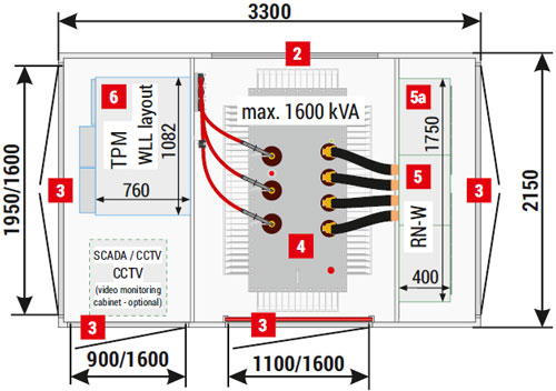
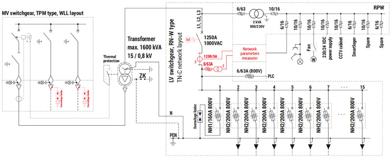
MRw (3,3x2,15) 20/1600-3
The station is dedicated to large-scale photovoltaic installations, the main body is integrated with a metal foundation - low weight ~ 7.5T with an installed transformer. The station can be transported as a whole, including the transformer.

| 1 | Substation placement part — metal foundation |
| 2 | Ventilation louvres IP 23D - standard, IP 43 - optional |
| 3 | Doors: solid or with ventilation louvres IP 23D - standard, IP 43 - optional |
| 4 | Transformer |
| 5 | LV switchgear |
| 5a | AMI cabinet / telemetry / auxiliary |
| 6 | MV switchgear |
Note!
The catalogue presents example substation configurations.
| Mass / Area | |
| Total mass with transformer | 7 500 kg |
| Metal main structure | 2 800 kg |
| Metal roof | 500 kg |
| Usable area | 7,1 m2 |
| Technical parameters / configuration possibilities | |||
| Transformer* (4) Maximum power / dimension | 1600 kVA / 1300 x 1900 x 1950 [mm] | ||
| Enclosure class | 10 | ||
| Electrical parameters of switchgears | MV | LV | |
| Rated voltage | up to 25 kV | up to 0,8 kV | |
| Rated current | 630 A | up to 1250 A | |
| Rated short-time withstand current | up to 25 kA (1s) | up to 35 kA (1s) | |
| Rated peak withstand current | up to 63 kA | up to 77 kA | |
| Switchgear** | Type | Maximum number of bays | |
| LV (5) | RN-W | 15 | |
| MV (6) | TPM | 3 (WLL) | |
* Transformer inserted from above, before the roof is attached.
** Detailed selection of switchgears and their equipment is listed in chapters dedicated to individual devices in the catalogue. Example layouts of switchgears and corresponding substation configurations are specified in parentheses.
*** LV station side may operate with TN-C and IT type low voltage cable grids.


