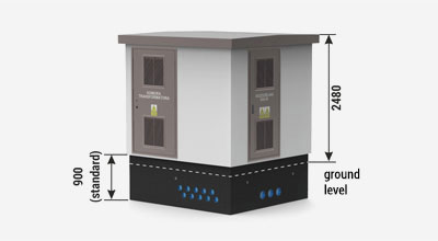
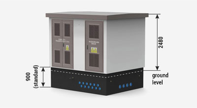
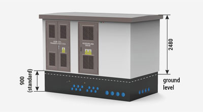
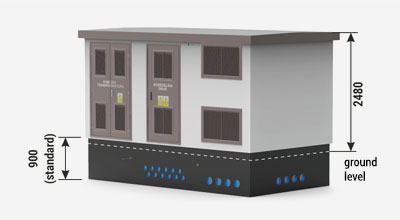
{tab Characteristics}
Transformer stations variants
The webside presents only exemplary solutions of the container stations.
Thanks to many years of experience and a team of qualified engineers, we are able to prepare solutions corresponding to the needs of the most demanding clients. The best example is in the deliveries for contractors such as: PGE, TAURON, ENERGA, ENEA, RWE, PKP Energetyka, KGHM, KWB Bełchatów, ČEZ, EON, RWE, Alstom and many more.
Single transformer station
Double transformer station
Example of a station with fire shutters and high-current power transformer (2000 kVA)
Dimensions of concrete casings
b – length [mm] | a – width [mm] | |||||
2350 | 2450 | 2600 | 3000 | 3560 | ||
4200 | + | + | + | + | ||
4700 | + | + | ||||
4760 | + | |||||
5400 | + | + | + | + | ||
5460 | + | |||||
6100 | + | + | + | |||
6600 | + | + | + | |||
7100 | + | + | + | |||
8100 | + | + | + | |||
wall thickness [mm] | 90/120 3.* | 90/120 3.* | 90/120 3.* | 90/120 3.* | 120 |
Notice:
- Station can be designed in mirror ver-sion.
- Housing with 120 mm wall thickness can be made with back and side walls of REI 120 fire protection.
- * The table shows housings with 90mm thick walls. In case of housings 120 mm walls thickness, you should add 60mm to the external housing dimensions.
Technical data
Stations parameters | |||
Switchgear | |||
MV | LV | ||
Ur | - Rated voltage | up to 36 kV | up to 1000 V |
Ir | - Rated current | up to 4000 A | up to 6300 A |
IK | - Rated short-time withstand current | up to 40 kA (3s) | up to 105 kA (1s) |
IP | - Rated peak withstand current | up to 100 kA | up to 231 kA |
fr | - Power frequency withstand | 50/60 Hz | |
Maximum transformer power | up to 4000 kVA | ||
Protection degree | IP23D up to IP43 (IP54) |
Stations have been examined with regard to existing standards in accredited European laborato-ries.
Compliance with the standards
- PN-EN 62271-202 - High-voltage switchgear and controlgear - Part 202: High-voltage/ low-voltage prefabricated substation;
+ related norms
Localization of the station due to fire safety requirements
The mounting area of the station should be chosen in accordance with the regulation of the Minister of Infrastructure of 12 April 2002, with regard to the technical requirements of buildings localization (Journal of Laws of 15 June 2002, No 75, item 690, with later changes) or local regulations.
Individual cases of localization/placing of the station should be considered on an individual basis and consulted with ZPUE S.A. or with other authorized services (opinion given by fire protection officer).
{tab Station construction} {tab Roof types} {tab MV and LV cable glands} {tab Colouristics}
WALLS AND CEILLINGS FINISH
Internal and external walls are covered with decorative white acrylic plaster. All metal elements installed outside the station are made from powder-coated aluminium according to the RAL color palette. Colouristics as well as elevation type are offered in the standard version (table below). It is also possible to design the station according to individual architectural requirements, taking into account all available materials to finish the concrete and metal surfaces (door, louvres), roofing slopes, and roof flashings.
STANDARD COLOUR SETS
Housing color (acrylic plaster) | Color similar to | |
White | ![]() |
RAL 9016 |
TEXAS TX2 | ![]() |
RAL 1013 |
ETNA ET2 | ![]() |
RAL 7044 |
FLORIDA FL2 | ![]() |
RAL 1015 |
ATLANTIC AT2 | ![]() |
RAL 7047 |
MADEIRA MD1 | ![]() |
RAL 1013 |
SAVANNE SV4 | ![]() |
RAL 1001 |
POLAR PL1 | ![]() |
RAL 7047 |
BALI BL2 | ![]() |
RAL 6019 |
Carpentry colour (door, shutters, roof) | |
RAL 9016 | ![]() |
RAL 7032 | ![]() |
RAL 3003 | ![]() |
RAL 5010 | ![]() |
RAL 6001 | ![]() |
RAL 7024 | ![]() |
RAL 8004 | ![]() |
RAL 8007 | ![]() |
RAL 8017 | ![]() |
Notice:
The colors shown in the table may differ from those in reality! When selecting colors should always be compared with the original template colors.
TRANSPORT
ZPUE S.A., as one of few companies that manu-factures prefabricated container stations, has its own fleet. Transport services provided by the company are aimed to lower the costs of trans-porting ZPUE S.A. devices and to improve the quality of customer service. We offer a transport set with a total permissible weight of 70 tonnes, which can transport even 50 tonnes of load. We have the latest generation of vehicles with Euro 6 exhaust emission (a norm of limiting exhaust emission by new vehicles sold in the European Union).
EXAMPLE OF THE TRANSFORMER STATION TRANSPORT
PLACING STATION
Trench excavation is the first step in placing the station. In the trench, external grounding of the station should be made in the form of a grounded outer ring (or another in accordance with local requirements in terms of grounded electrical power devices).
Under the fundament sand and gravel ballast should be used with at least 20 cm final thickness (after density). The thickness of the base made of sand and gravel must be adapted to local soil-water conditions and the frost zone. The sand and gravel ballast area must be leveled for the station, and the quality of grounding prepared should be confirmed by the certificate of final acceptance.
The foundation of the station there should be placed in a place prepared in this way. The walls of the foundation should be covered with single sealing tape. It is important to avoid the application of the tape on itself (not to make a double layer). The sealing tape must not be stretched during application, as this can cause damage or defor-mation.
On the properly prepared fundament, the main body can be placed in the exact position, followed by the roof.
Strew the fundament gradually with concentrated 20cm layer of filter ground. Particular attention should be paid while stewing the trench near the fundament’s wall so as to not damage the water-proofing of the vertical surfaces. The place where the cables enter to the ducts should be carefully stewed, because mechanical density can cause damage to these elements.
The fundament’s walls should extend no less than 10 cm above the finished area. Placing on difficult and complicated ground and water conditions, and in mining and post-mining areas should be performed after the elaboration of an individual project. It should be done by ab authorized engineering- geological designer, under qualified construction supervision.
EXAMPLE PLACING OF THE STATION