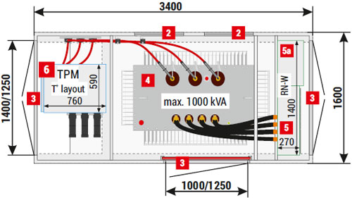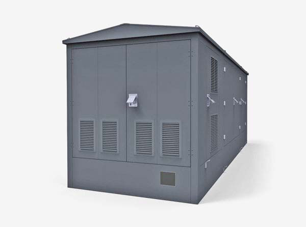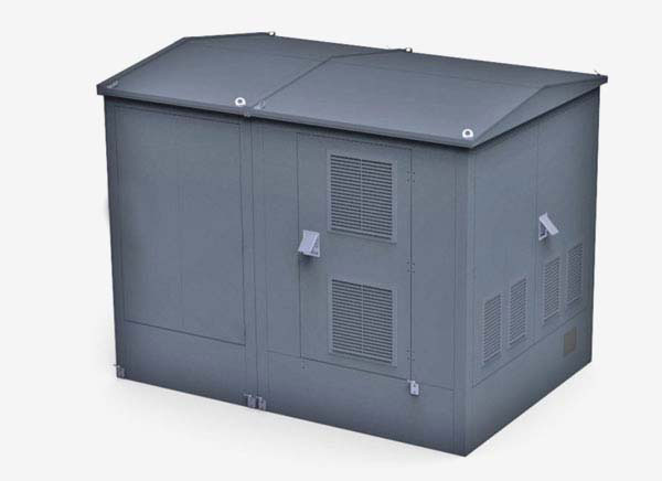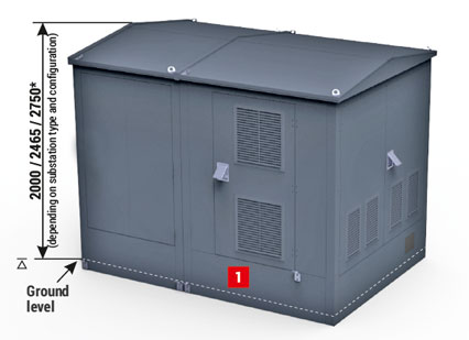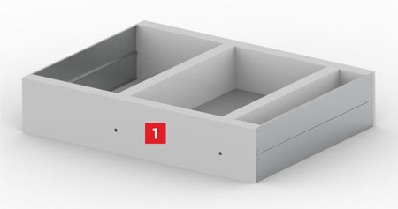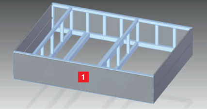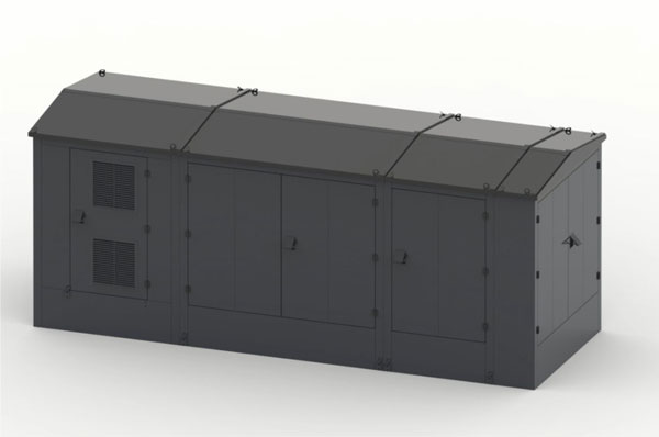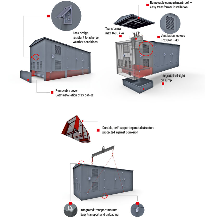
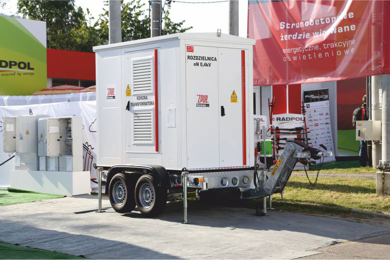
Failures or overhauls of transmission grid or transformer substation, the need for temporary supply to the customers and for rapid supply of power, without the option of connection to an MV grid, with the use of a power generator unit are a few examples of factors which resulted in the design of a light substation in a metal enclosure, on a transport chassis with a gross vehicle weight rating GVWR of 3.5T, which can be towed by a truck, for example. The substation enclosure is formed by a light, spatial, self-supporting metal structure made of structural steel connected by welding and bolting. The entire structure is protected against corrosion and powder painted.
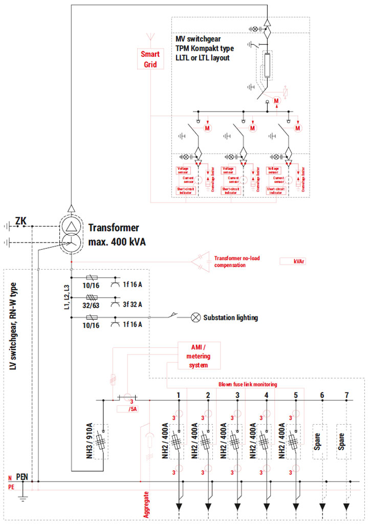
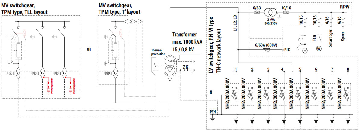
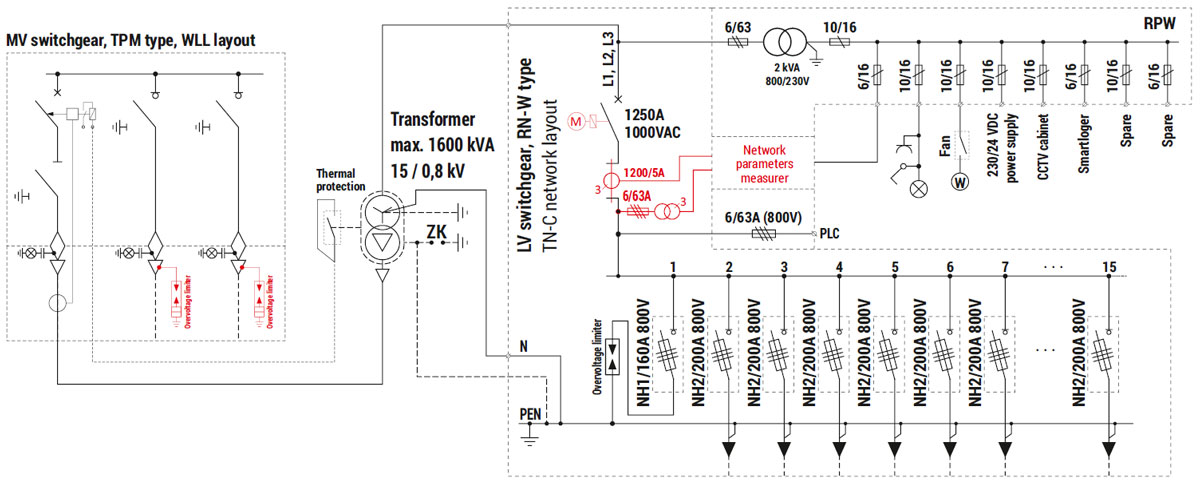
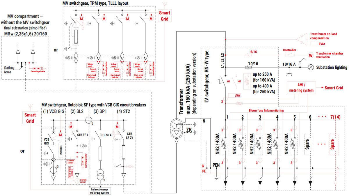
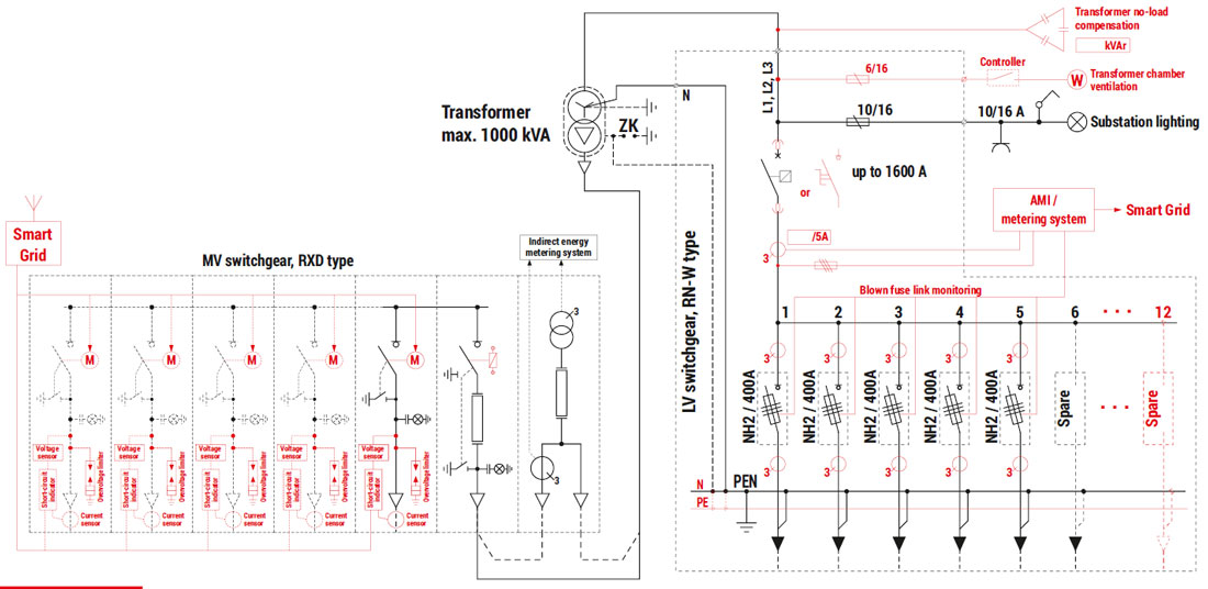
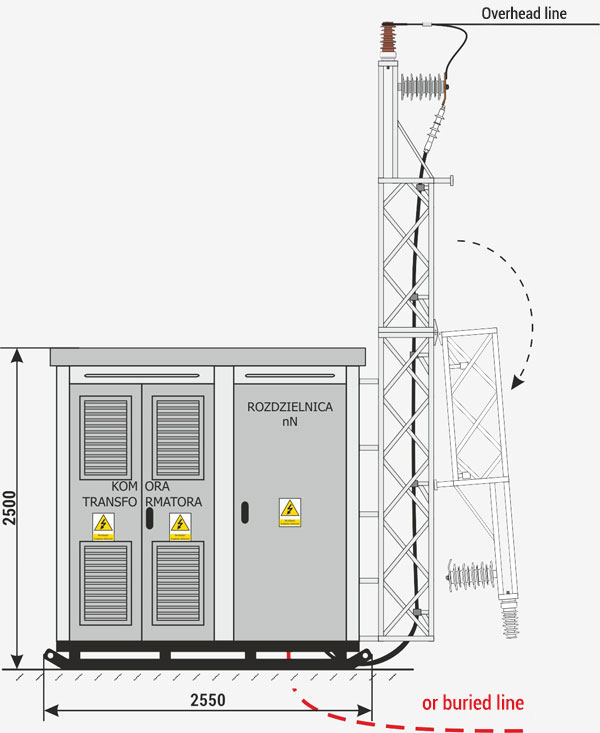
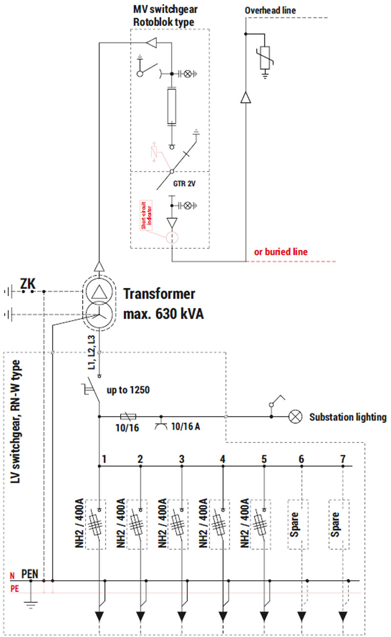
Stations use state of the art TPM type MV switchgear in gas insulation and RN-W type LV switchgear with the possibility of connecting a power generator unit, operated from the outside, after previously opening the doors to an appropriate compartment. These switchgear are commonly used in the commercial power sector as elements which provide power supply and protection to transformer units.
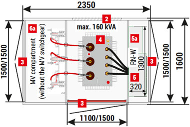
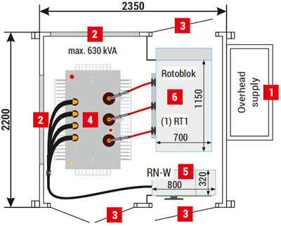
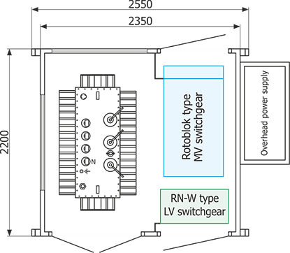
The station may house a transformer with a maximum power up to 400 kVA (with gravity ventilation), installed after roof removal. The transformer is permanently installed in the substation, which enables it to be transported without the need to remove the transformer.
The presented solution should be considered an example. ZPUE S.A. has in its offer a very wide range of transformer substation and MV and LV switchgear solutions, which enable the performance of very advanced control and protection functions, including automation logic which enables uninterrupted restoration or reconfiguration of the power supply. These solutions are selected individually and may differ from the one presented in the publication.
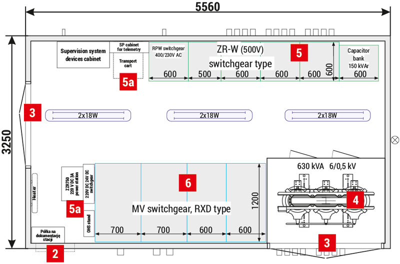
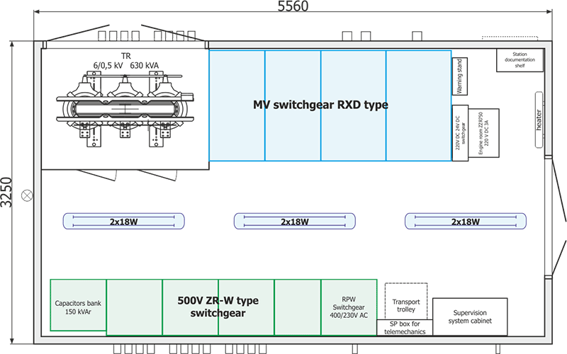
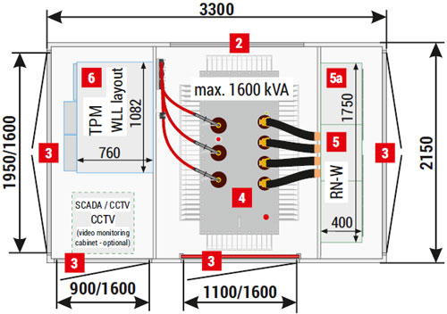
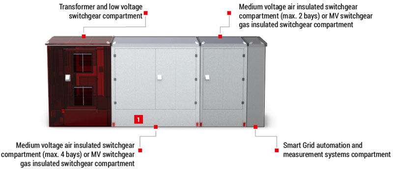
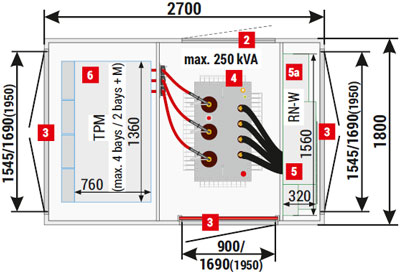
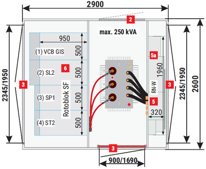
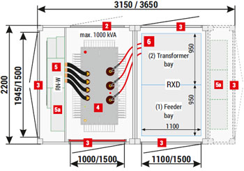
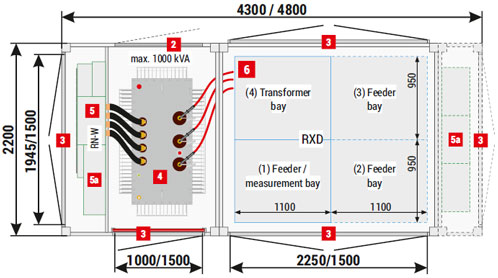
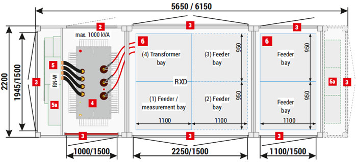
Placement of equipment
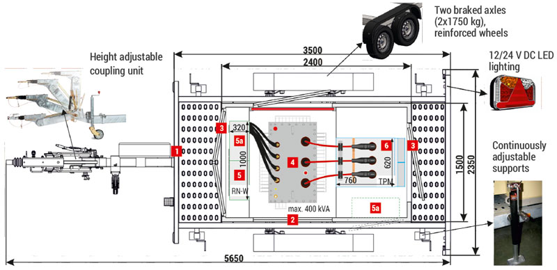
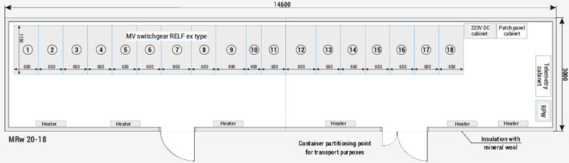
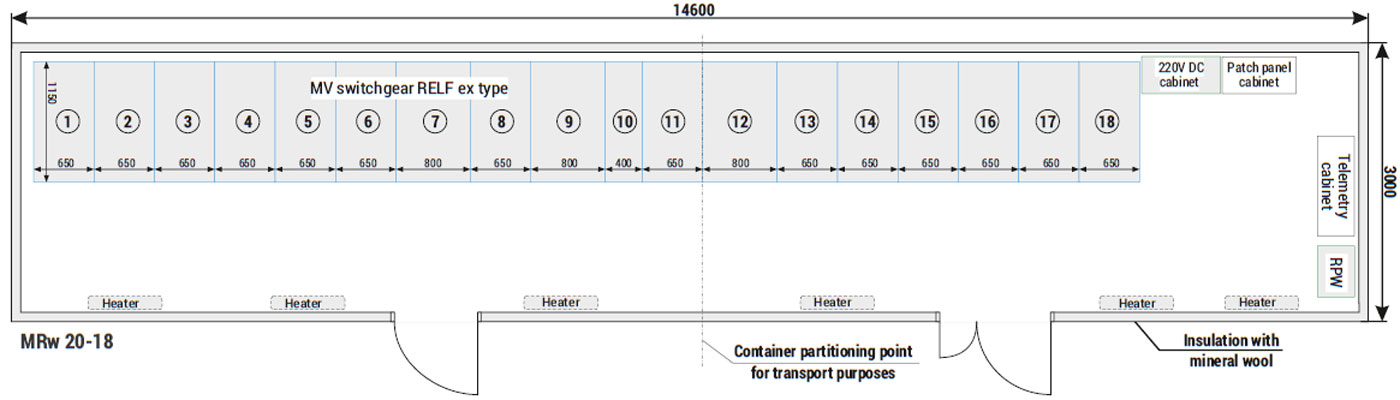
| 1 | Transport chassis - trailer |
| 2 | Ventilation grating IP 23D - standard, IP 43 - optional |
| 3 | Doors: solid or with ventilation louvres IP 23D - standard, or IP 43 - option |
| 4 | Transformer |
| 5 | LV switchgear |
| 5a | AMI cabinet / Smart Grid / telemetry / auxiliary |
| 6 | MV switchgear |
Note!
The catalogue presents example substation configurations.