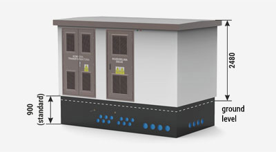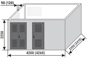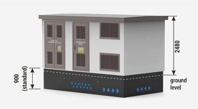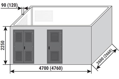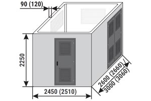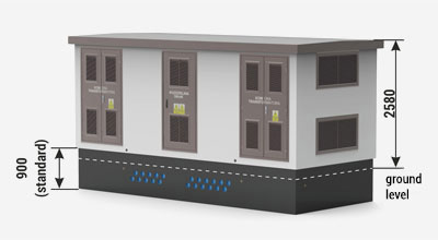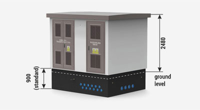
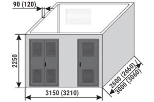
| External/internal height of the main structure of the substation: | |
| Standard | 2250 mm / 2150 mm |
| Optional | 2650 mm / 2450 mm or 3000 mm / 2800 mm |
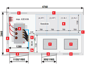
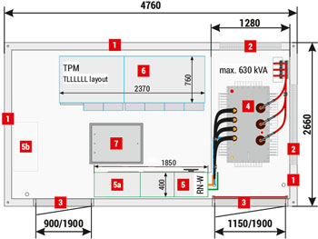
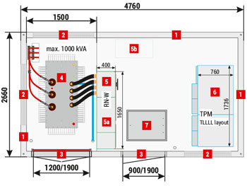
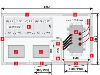
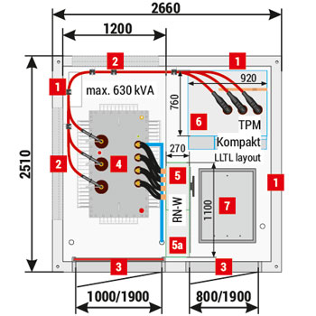
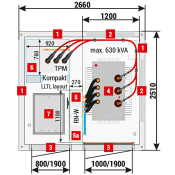
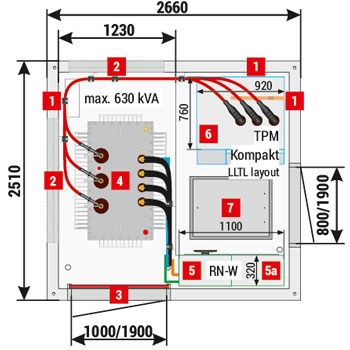
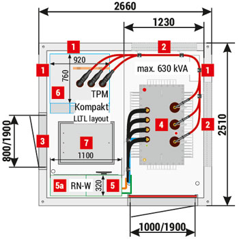
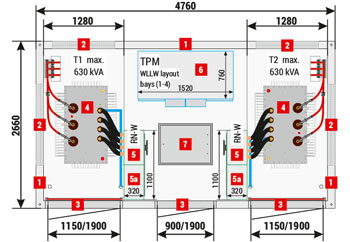
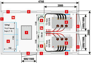
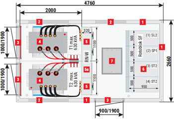
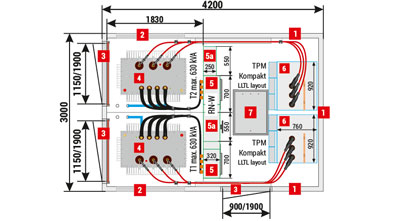
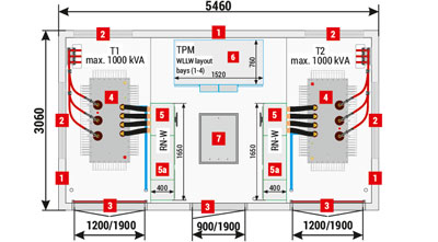
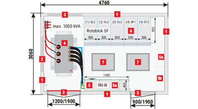
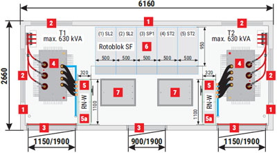
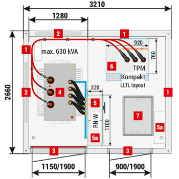
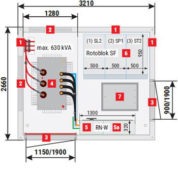
Placement of equipment
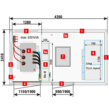
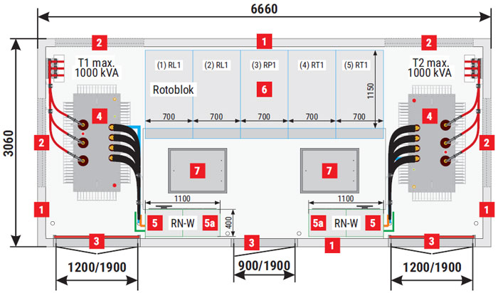
MRw-b2(pp) 20/630-4"a”
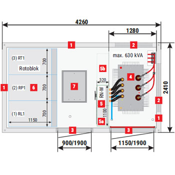
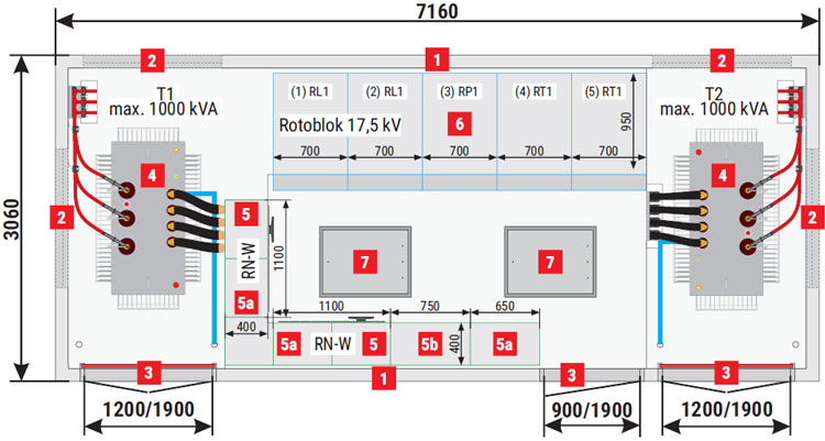
MRw-b2(pp) 20/630-3"b”
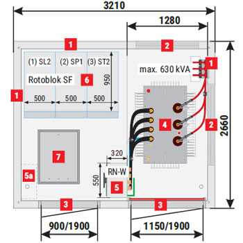
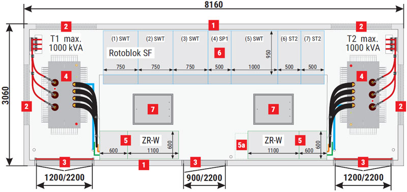
MRw-b2(pp) 20/630-3"c”
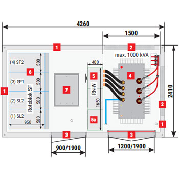
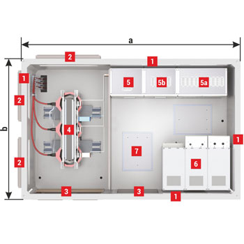
MRw-b2(pp) 20/630-4"d”
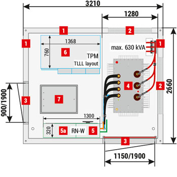
| 1 | Walls, 120 mm thick - standard, 90 mm - optional Solid walls - REI 120 fire integrity class |
| 2 | Ventilation louvres IP 23D - standard, IP 43 - optional In ventilation louvres mounted in walls with fire integrity class, fire dampers are installed (e.g. EI 60 or EIS 120) - optional |
| 3 | Doors: solid or with ventilation louvres without fire integrity class, IP 23D - standard, IP 43 - optional Doors with fire resistance e.g EI 60 or EI 120 - optional |
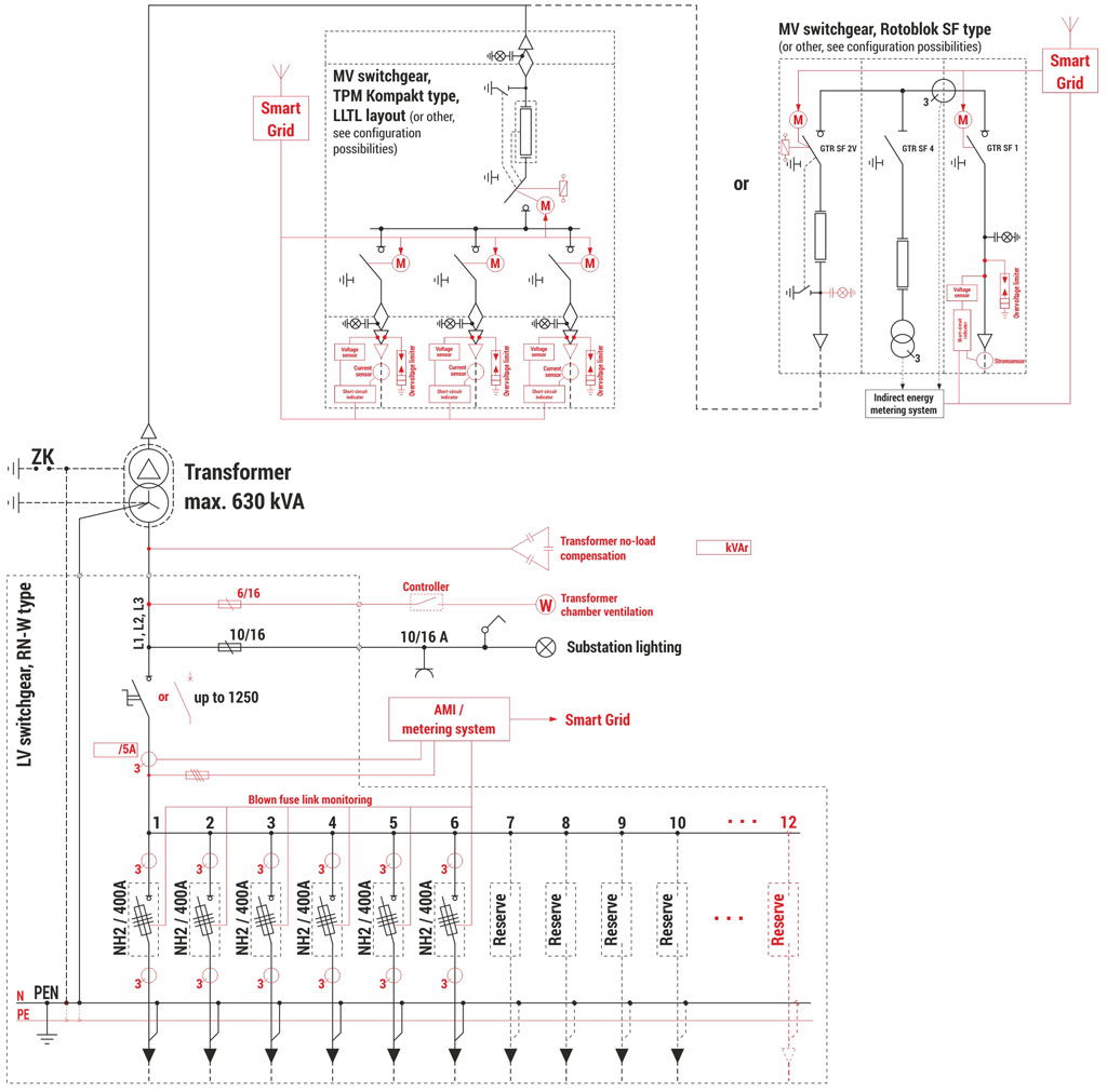
| 4 | Transformer |
| 5 | LV switchgear |
| 5a | AMI cabinet / Smart Grid / telemetry / auxiliary |
| 6 | MV switchgear |
| 7 | Cable duct hatch door |
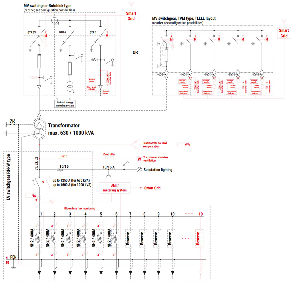
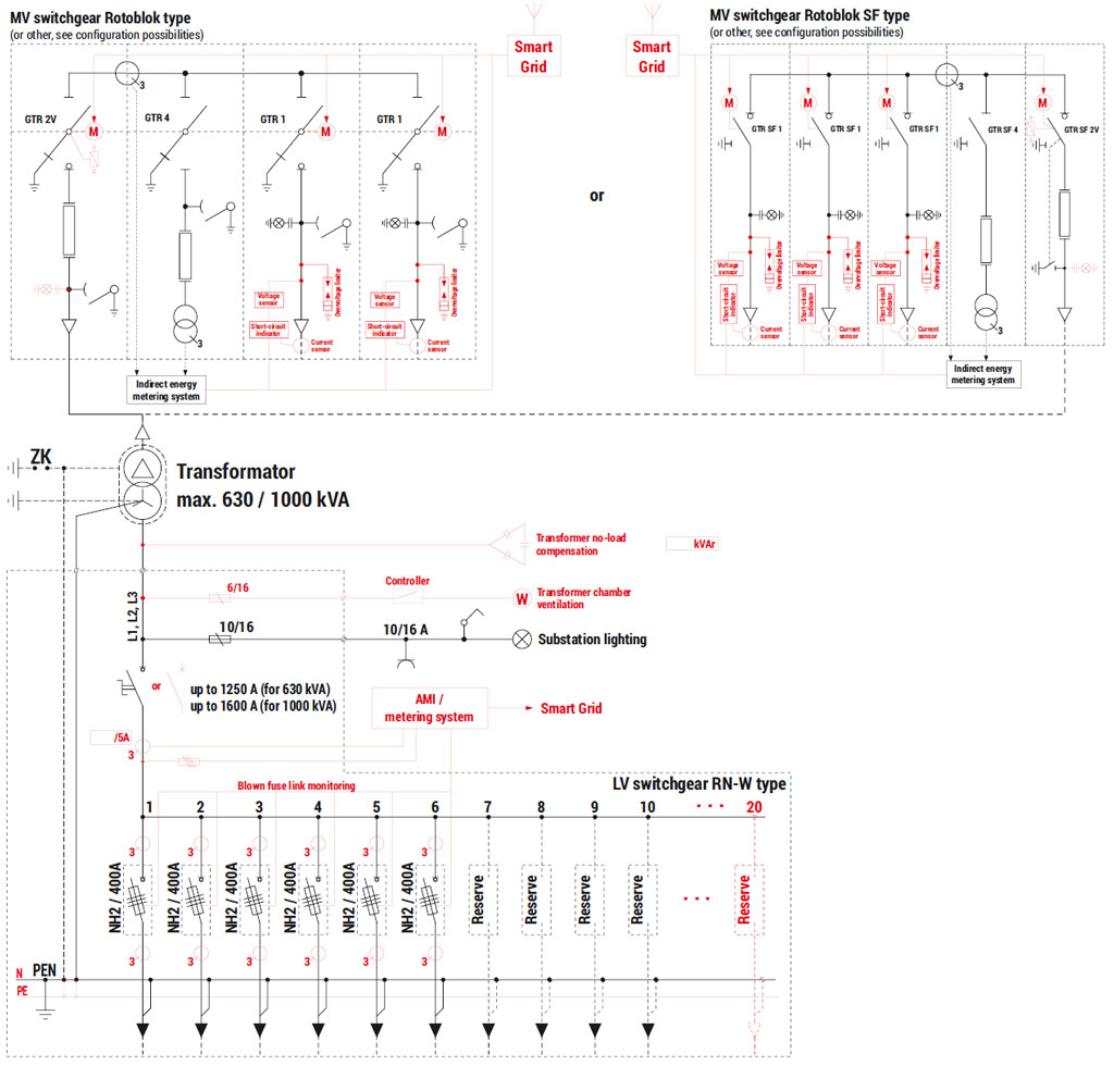
Technical parameters / configuration possibilities
| Mass / Area | |
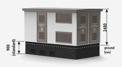
| Foundation | 4 500 kg |
| Main structure | 11 000 kg |
| Concrete roof | 3 200 kg |
| Metal roof | 450-600 kg |
| Usable area | 7,18 m2 |
| Technical parameters / configuration possibilities | |||
| Transformer (4) Maximum power / dimension | 630 kVA / 980* x 2000 x 1850 [mm] | ||
| Internal arc resistance classification | IAC-AB-20 kA-1s | ||
| Enclosure class | up to 10 (depending on substation configuration) | ||
| Electrical parameters of switchgears | MV | LV | |
| Rated voltage | up to 25 kV | up to 0,69 kV | |
| Rated current | 630 A | up to 1250 A | |
| Rated short-time withstand current | up to 20 kA (1s) | up to 25 kA (1s) | |
| Rated peak withstand current | up to 50 kA | up to 52,5 kA | |
| Switchgear** | Typ | Maximum number of bays | |
| LV (5) | RN-W | 5 / 10 / 12 (depending on configuration) | |
| MV (6) | TPM / TPM Kompakt | 4 (TLLL „c”, „d”) / 4 (LLTL) | |
| Rotoblok SF (500) | 3 (for „a” or „b” - LV max. 5) | ||
* Maximum width of the transformer installed through the substation doors. Wider transformers may be installed from the top.
** Detailed selection of switchgears and their equipment is listed in chapters dedicated to individual devices in the catalogue. Example layouts of switchgears and corresponding substation configurations are specified in parentheses, if any.