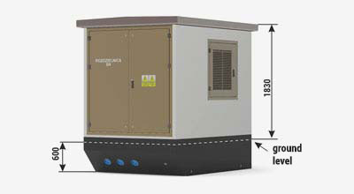
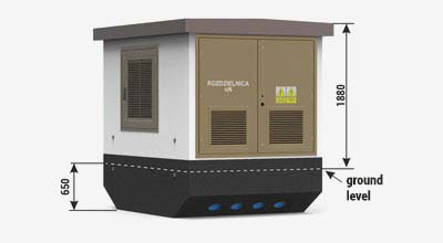
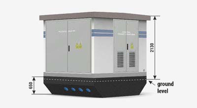
{tab Characteristics}
Transformer stations variants
The webside presents only exemplary solutions of the container stations.
Thanks to many years of experience and a team of qualified engineers, we are able to prepare solutions corresponding to the needs of the most demanding clients. The best example is in the deliveries for contractors such as: PGE, TAURON, ENERGA, ENEA, RWE, PKP Energetyka, KGHM, KWB Bełchatów, ČEZ, EON, RWE, Alstom and many more.
Station type Mzb 20/2x630
Diagram of the standard station type Mzb 20/2x630
Notice:
Configuration options
Type | MV bay number (LV feeders) |
|
MV switchgear | TPM | up to 2x4 |
LV switchgear | RN-W | up to 2x10 |
Maximum transformer power | up to 2x630 kVA | |
Housing class - 20 |
Weight
main body: | 16 500 kg |
concrete roof: | 4 500 kg |
metal roof: | 600-700 kg |
usable area: | 10,93 m2 |
Localization of the station due to fire safety requirements
The mounting area of the station should be chosen in accordance with the regulation of the Minister of Infrastructure of 12 April 2002, with regard to the technical requirements of buildings localization (Journal of Laws of 15 June 2002, No 75, item 690, with later changes) or local regulations.
Individual cases of localization/placing of the station should be considered on an individual basis and consulted with ZPUE S.A. or with other authorized services (opinion given by fire protection officer).
{tab Station construction} {tab Roof type} {tab MV and HV cable glands} {tab Colouristics}
WALLS AND CEILLINGS FINISH
Internal and external walls are covered with decorative white acrylic plaster. All metal elements installed outside the station are made from powder-coated aluminium according to the RAL color palette. Colouristics as well as elevation type are offered in the standard version (table below). It is also possible to design the station according to individual architectural requirements, taking into account all available materials to finish the concrete and metal surfaces (door, louvres), roofing slopes, and roof flashings.
STANDARD COLOUR SETS
Housing color (acrylic plaster) | Color similar to | |
White | ![]() |
RAL 9016 |
TEXAS TX2 | ![]() |
RAL 1013 |
ETNA ET2 | ![]() |
RAL 7044 |
FLORIDA FL2 | ![]() |
RAL 1015 |
ATLANTIC AT2 | ![]() |
RAL 7047 |
MADEIRA MD1 | ![]() |
RAL 1013 |
SAVANNE SV4 | ![]() |
RAL 1001 |
POLAR PL1 | ![]() |
RAL 7047 |
BALI BL2 | ![]() |
RAL 6019 |
Carpentry colour (door, shutters, roof) | |
RAL 9016 | ![]() |
RAL 7032 | ![]() |
RAL 3003 | ![]() |
RAL 5010 | ![]() |
RAL 6001 | ![]() |
RAL 7024 | ![]() |
RAL 8004 | ![]() |
RAL 8007 | ![]() |
RAL 8017 | ![]() |
Notice:
The colors shown in the table may differ from those in reality! When selecting colors should always be compared with the original template colors.
TRANSPORT
ZPUE S.A., as one of few companies that manu-factures prefabricated container stations, has its own fleet. Transport services provided by the company are aimed to lower the costs of trans-porting ZPUE S.A. devices and to improve the quality of customer service. We offer a transport set with a total permissible weight of 70 tonnes, which can transport even 50 tonnes of load. We have the latest generation of vehicles with Euro 6 exhaust emission (a norm of limiting exhaust emission by new vehicles sold in the European Union).
EXAMPLE OF THE TRANSFORMER STATION TRANSPORT
PLACING STATION
Trench excavation is the first step in placing the station. External grounding of the station should be made in the trench. It is recom-mended that it should be made in the form of a grounding outer ring or other method, in accordance with local requirements in terms of grounding electrical power devices.
Under the foundation, sand and gravel ballast should be used and be at least 20 cm in final thickness (after compacting). The thickness of the sand and gravel base must be adapted to local soil-water conditions and the frost zone. The sand and gravel ballast area must be leveled for the station, and the quality of grounding prepared should be confirmed by the certificate of final acceptance.
In the prepared place, the following should be mounted successively: the foundation of the station, transformer (from the top of the station, setting it on rails), and finally the roof. Cover the foundation gradually with a concentrated 20cm layer of filter ground. Particular attention should be paid while covering the trench near the foundation’s wall to not damage the waterproofing of the vertical surfaces. The place where the cables enter to the glands should be carefully covered, because mechanical compacting can cause damage to these elements.
The foundation’s walls with the insulation against the moisture should extend no less than 10 cm above the finished area.
Placing on difficult and complicated ground and water conditions, and in mining and post-mining areas should be performed after drawing up of an individual project. It should be done by an authorized engineering- geological designer, under qualified construc-tion supervision.
EXAMPLE PLACING OF THE STATION