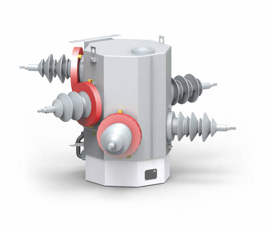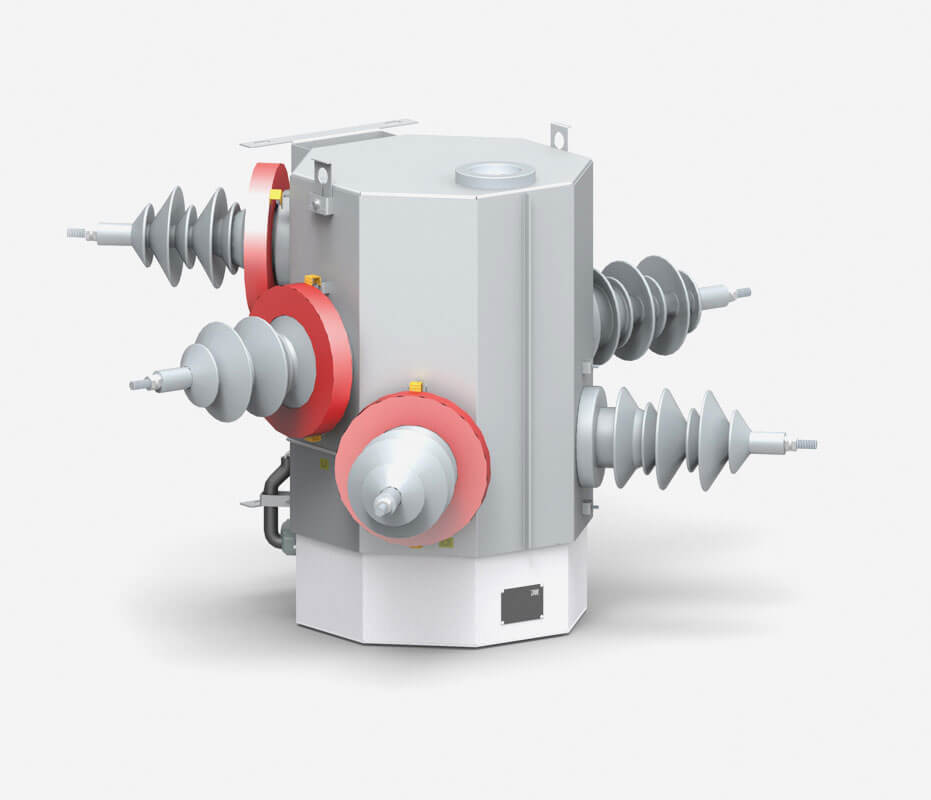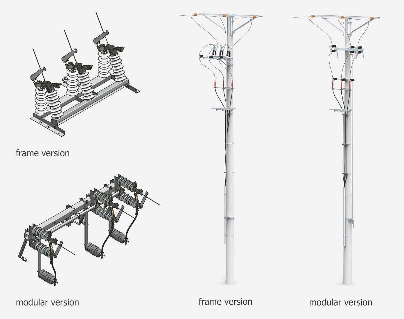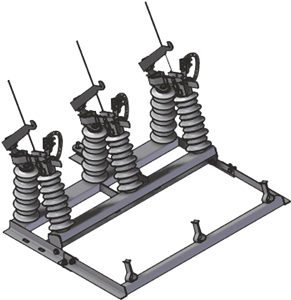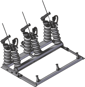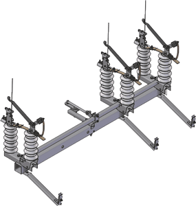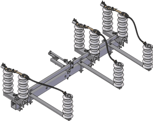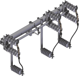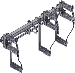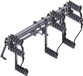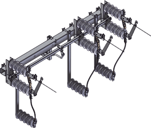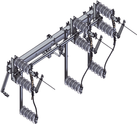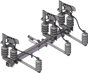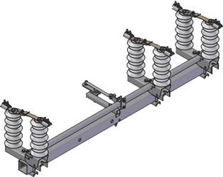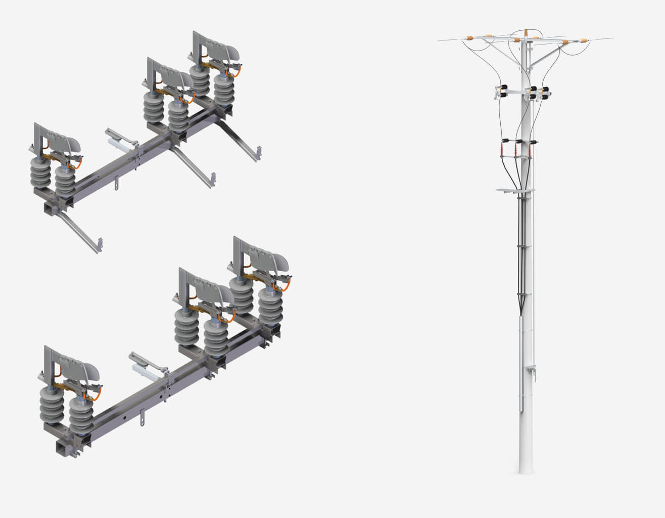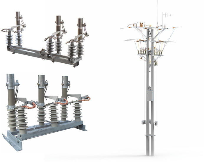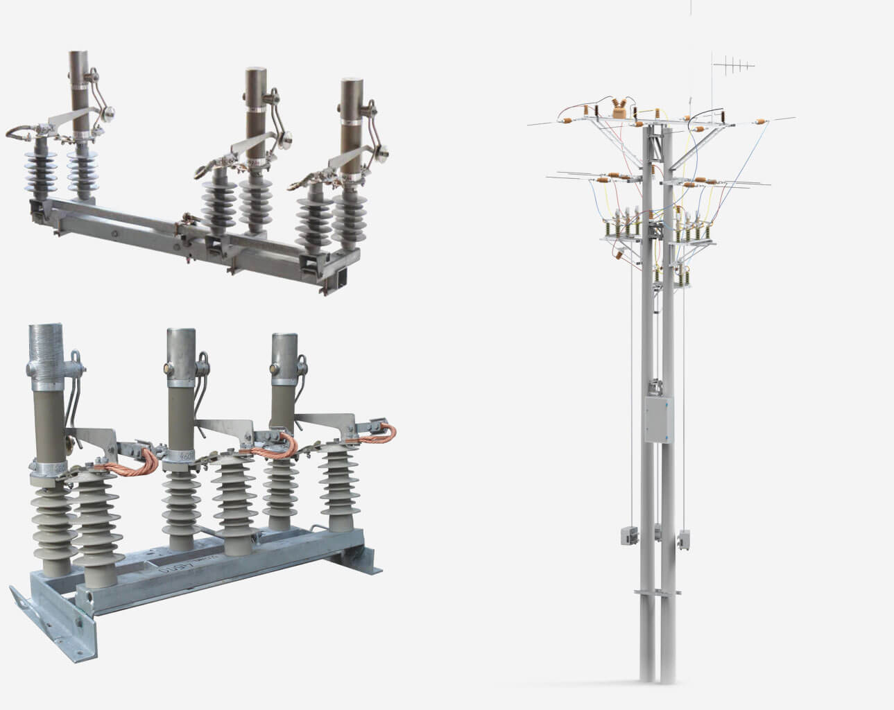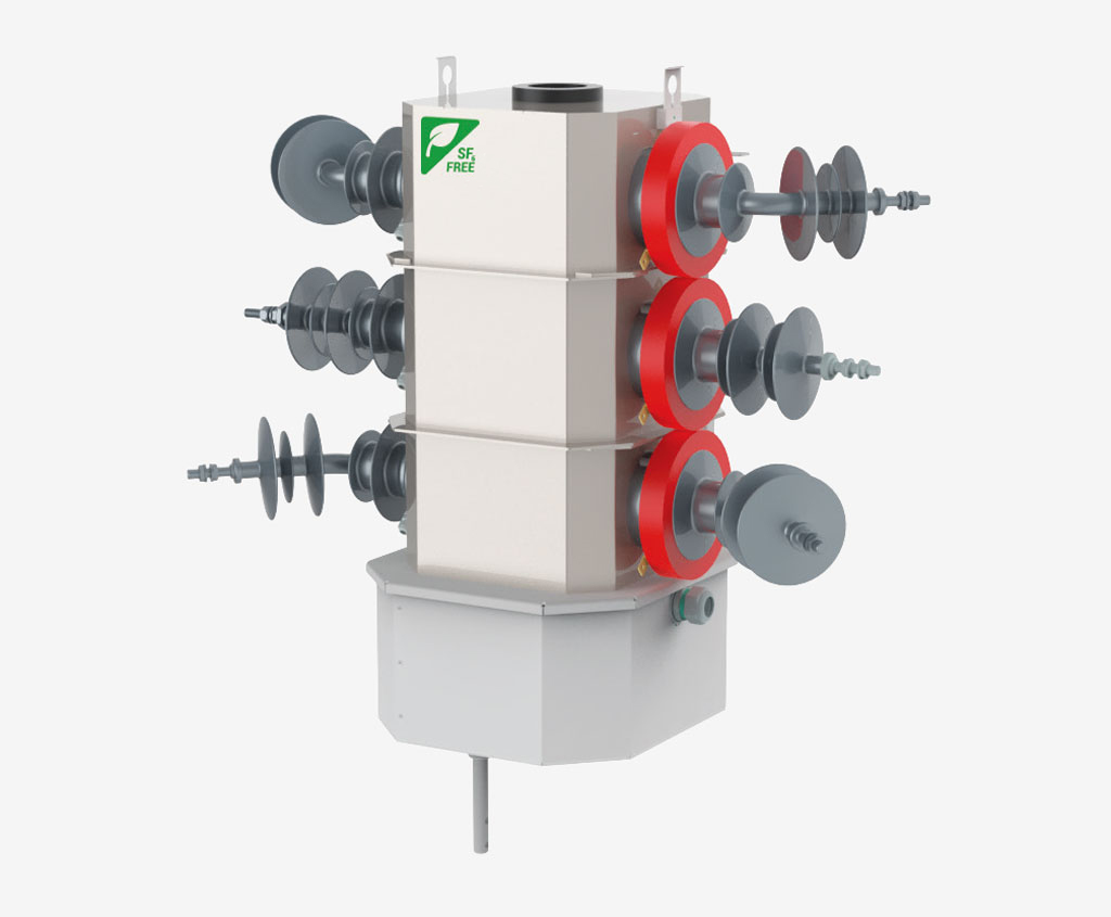
The THO Air enclosed overhead disconnector is a modern device used mainly in advanced smart grids, SPZ automation and modern automation systems, e.g. FDiR.
Extensive experience in the production of switching equipment from scratch, hundreds of projects and the implementation of new technologies and design solutions have enabled us to create an overhead disconnector with a dry air insulation enclosure.
This disconnector directly replaces the previous THO-24 and THO 2-24 generation disconnectors, while maintaining high electrical parameters and the existing capabilities of comprehensive parameter monitoring and overhead line protection.
Characteristics
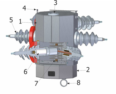
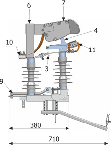
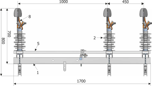
Construction
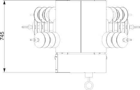
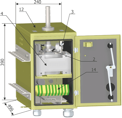
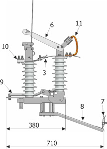
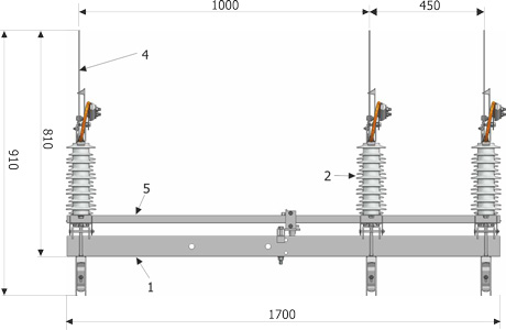
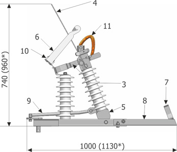
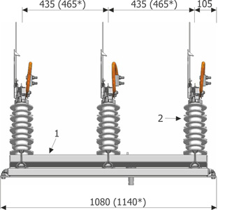
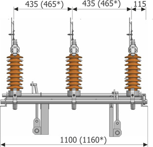
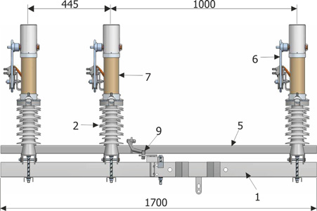
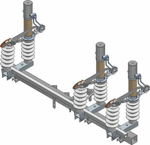
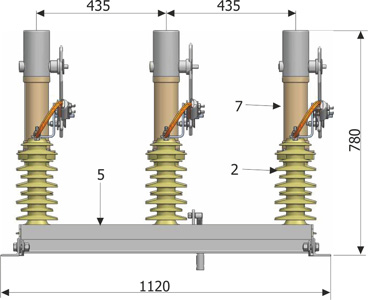
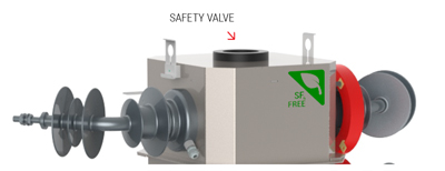
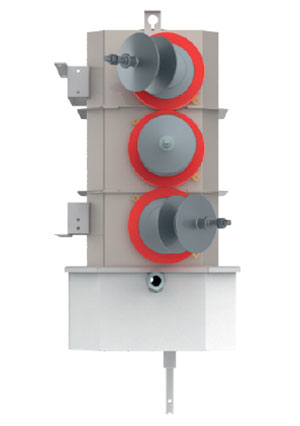
- The innovative design of the disconnector is enclosed in a sealed stainless steel tank with IP67 protection rating in dry air insulation. This guarantees stable operating conditions and allows for high electrical parameters and excellent switching capacity. In addition, the enclosed design eliminates the need for maintenance or adjustment of the disconnector assemblies.
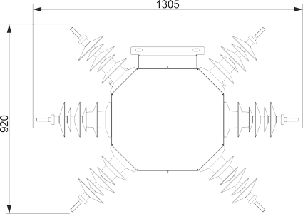
- The disconnector uses resin bushings covered with silicone rubber, adapted for operation in dry air insulation. The solution has excellent hydrophobic properties and an appropriate creepage distance for 24kV voltage and the highest pollution zone.
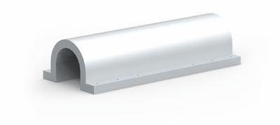
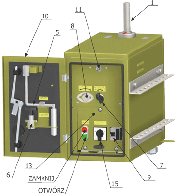
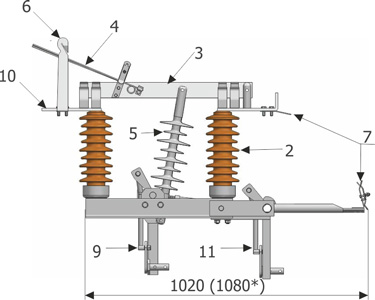
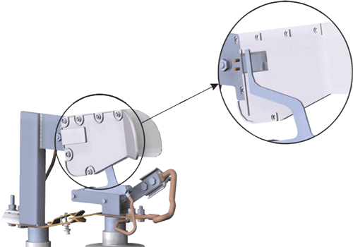
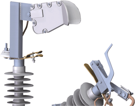
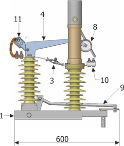
- The disconnect switch has a specially designed safety valve located at the top of the device. It protects the sealed tank against excessive pressure build-up inside, and its location at the top of the tank ensures safe operation.
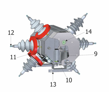
- The disconnect switch is always equipped with a pressure gauge to verify the dry air pressure level before performing the connection operation. It is also equipped with a pressure switch as standard, which transmits the pressure status to the telemechanics controller.
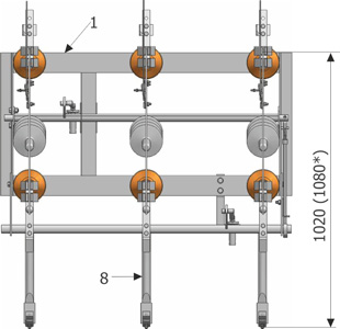
- The motor drive is directly coupled to the main working shaft and forms an integral part of the disconnector. Switching on and off is performed simultaneously for all three poles by means of a single common shaft. This eliminates the possibility of interference and reduces the possibility of incorrect signalling and manoeuvres.
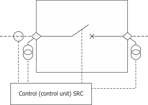
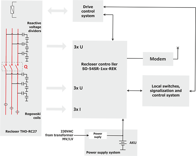
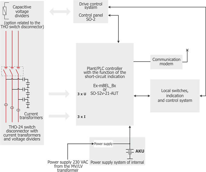
- In addition, the disconnector is usually equipped with current sensors (transformers or Rogowski coils) and voltage sensors (capacitive or resistive), which allows for automatic operation in automatic networks, ensuring comprehensive protection of overhead lines, full control of their parameters and quick location of short circuits or damage.
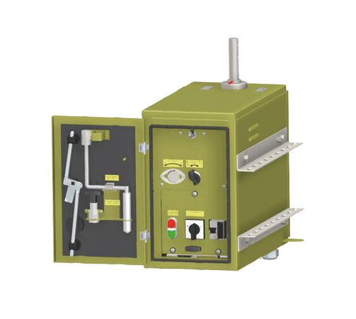
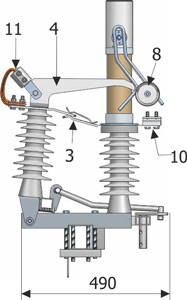
Engine drive
The disconnector equipped with a motor drive is mainly designed for remote control. It is also possible to operate the motor drive locally. The motor drive performs the ‘on’ and ‘off’ operations in less than 1.2 seconds.
Engine drive
The disconnector is always equipped with an emergency manual drive with a clutch. This type of solution guarantees smooth operation of the motor drive without unnecessary engagement of the manual drive cables. The manual drive is connected to the motor drive in only one place, which prevents incorrect manoeuvres. The coupling is also signalled to the controller, as a result of which this information is also sent to the network monitoring system and at the same time acts as an assembly lock.
The drive also has the option of fitting a standard padlock in any position.
Control cable
The disconnector is equipped with a dedicated control cable adjusted in length to the height of the disconnector installation at the target location.
The cable on the disconnector side is permanently factory-terminated, while on the cabinet side, the cable is terminated with marked plug connectors ready for connection.
This solution prevents incorrect connection of the device.
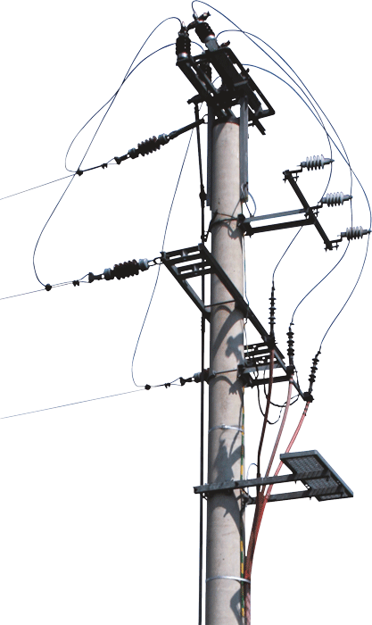
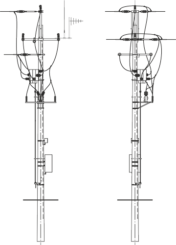
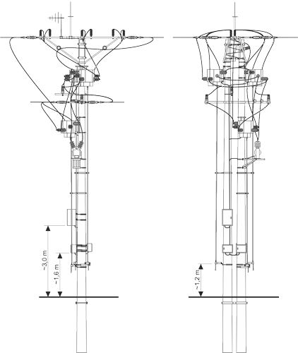
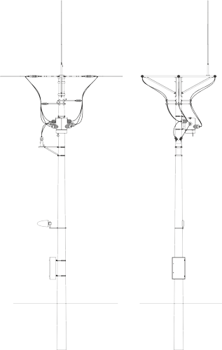
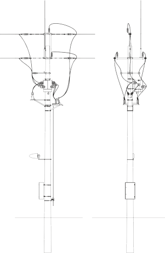
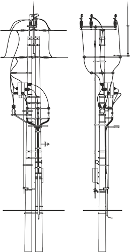
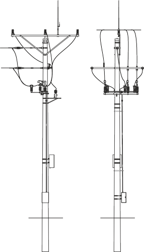
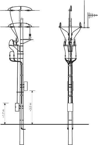
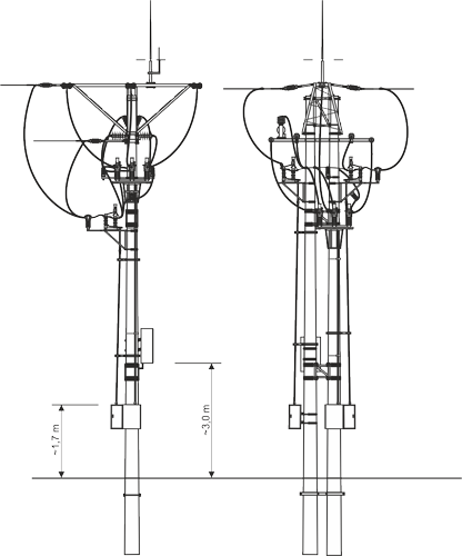
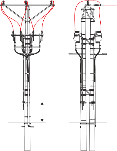
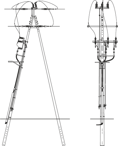
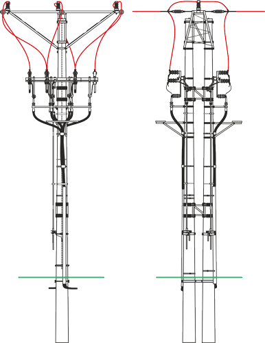
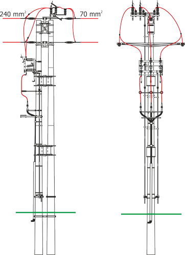
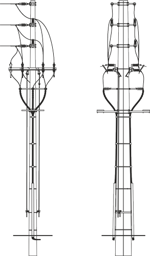
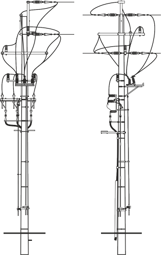
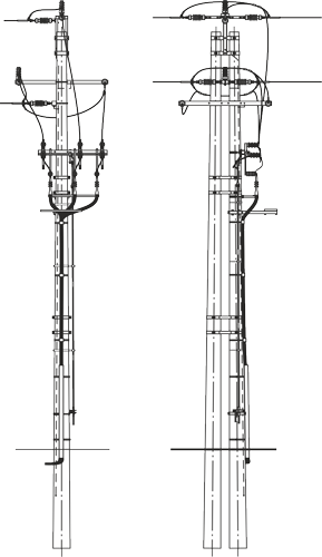
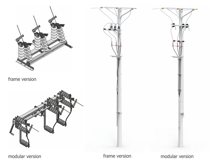
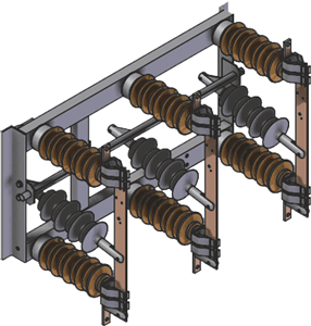
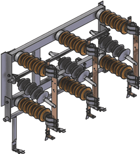
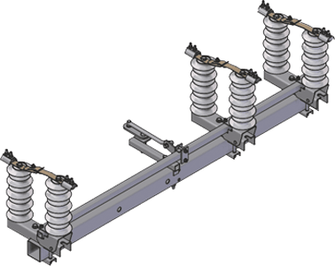
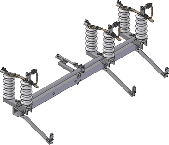
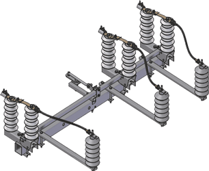
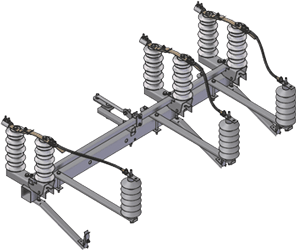
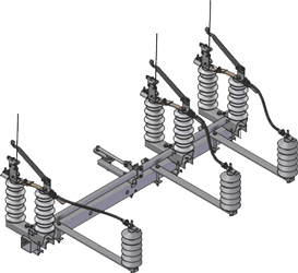
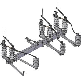
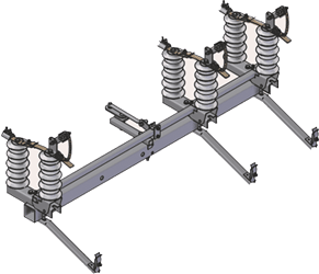
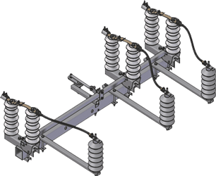
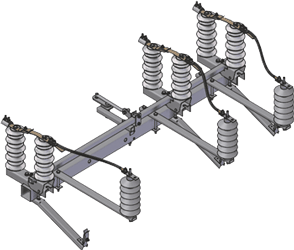
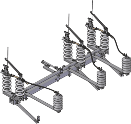
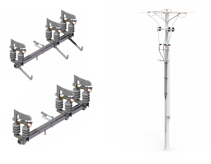
Fastening structure
The disconnector can be mounted on pole stations made of both spun poles and older types of reinforced concrete poles BSW/ŻN or non-standard concrete or steel lattice poles.
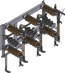
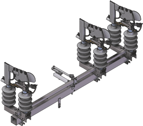
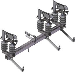
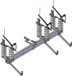
There is also a special design where a disconnector with an auxiliary transformer and surge arresters are mounted on a single common structure.

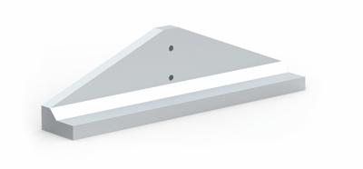
Safety valve
The disconnect switch has a specially designed safety valve located at the top of the tank. It protects the sealed tank against excessive pressure build-up inside.
Additional equipment
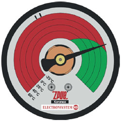
Pressure gauge
A pressure gauge with temperature compensation is standard equipment.
It is built into the drive compartment of the disconnector and is clearly visible from ground level.
The indicator has a scale divided into two zones:
- GREEN ZONE (correct level), where the indicator is located under normal conditions (it takes into account the effect of temperature on pressure changes inside the tank)
- RED ZONE, where the indicator signals a reduced state (emergency state in which disconnection operations cannot be performed).
Counter of completed operations
The meter is standard equipment.
It indicates the number of manoeuvres performed by the switch.
It is built into the drive compartment of the disconnector, visible from below.
Dedicated current clamps and bird-proof insulation covers
Dedicated clamps and covers are standard equipment.
They enable endless connection of overhead cables up to 185 mm2, and the covers ensure insulation of the connection.

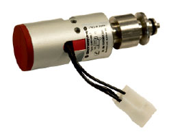
Pressure sensor (pressure switch) for telemechanics
The sensor signals a failure when the internal pressure drops to a level that prevents the disconnector from functioning properly. This also blocks switching operations.
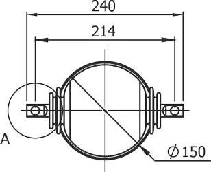
Current sensor parameters
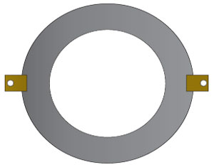
Parameters of PR-0.72 current transformers
The ring-shaped devices placed on the bushing insulators of the disconnector are connected in a Holmgreen configuration.
They are used to obtain information about earth fault currents and phase-to-phase currents, as well as to measure current as needed.
| Rated primary voltage Upr | 0,66 kV |
| Maximum permissible voltage of the transformer Um | 0,72 kV |
| Rated frequency fr | 50 Hz |
| Rated secondary current Ipr (Scope) | 50 A up to 600 A |
| Rated secondary current Isr | 1 A or 5 A |
| Power | 5 VA(10)* |
| Core parameters (Sr, kl., AFL) | 5(15)VA; 5P*; AFL-5* |
* Note! - Current transformers with other parameters are also available in special designs.
Parameters of PR-0.72s type current sensors (Rogowski coils)
| Rated primary voltage Upr | 0,66 kV |
| Maximum permissible voltage of the transformer Um | 0,72 kV |
| Rated frequency fr | 50 Hz |
| Rated secondary current Ipr (Scope) | 0,5 - 2000 A |
| Sensitivity | 1 mV/1 A or 5 mV/1 A* |
| Rated dynamic current Idyn | 5(15)VA; 5P*; AFL-5* |
| Accuracy | 1% |
Current sensors are installed on bushing insulators on the outflow side.
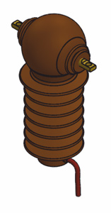
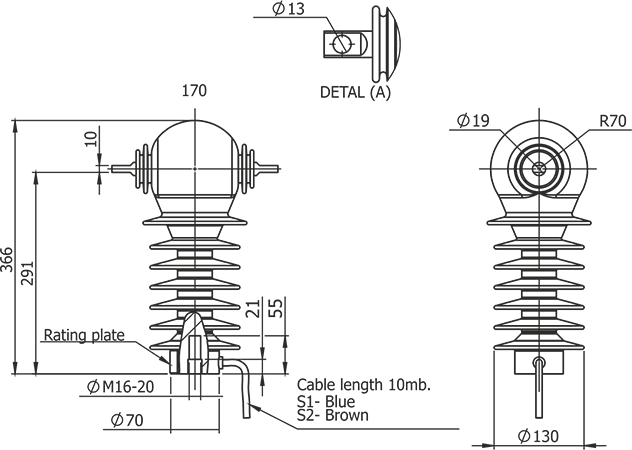
Voltage sensor parameters
Technical parameters of the capacitive voltage sensor
Voltage sensors built into the bushing insulators of the disconnector on the supply side.
| Rated primary voltage | 15/√3, 20/√3* |
| Maximum permissible voltage of the divider | 24 kV |
| Rated insulation test voltage | 55 kV |
| Lightning impulse withstand voltage 1.2/50μs | 125 kV |
| Capacitance of the upper capacitor built into the insulator | 21 pF |
| Capacitance of the lower capacitor in the amplifier | 200 nF / 267 nF* |
| Rated load | ≥200 kΩ |
| Rated secondary voltage | 3,25/√3 V* |
| Measurement accuracy after taking into account correction factors for voltage amplitude, class |
3P (1P)* |
| System operating temperature | -40°C + 60°C |
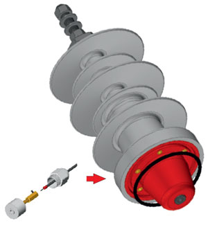
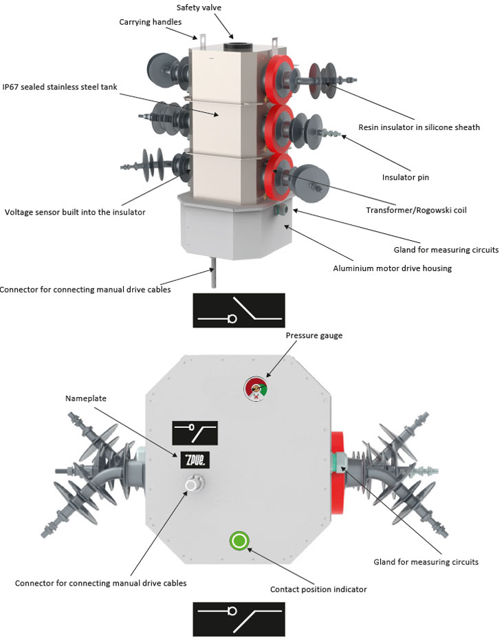
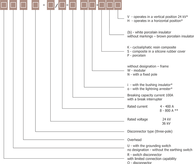
Table of symbols
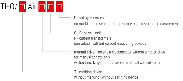
For example:
THO Air C-D Disconnector - means an overhead switch with a closed structure, dry air insulation for 24kV voltage, with a motor drive, Rogowski coils for current measurement and voltage sensors for presence control/voltage measurement.
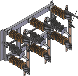
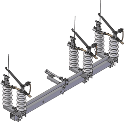
THO/T Air P-D Disconnector - means an overhead switchgear of closed construction, insulated with dry air for a voltage of 24kV, with an earthing switch, motor drive, current measuring transformers and voltage sensors for presence control/voltage measurement.
THO Air disconnect switch, manual operation - means an overhead disconnector of closed construction, dry air insulated, rated for 24kV, suitable for manual control, with the option of retrofitting a motor drive.
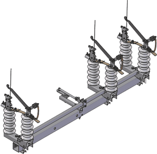
THO/T Air disconnect switch, manual operation - means an overhead disconnector of closed construction, dry air insulated, with an earthing switch, rated for 24kV, suitable for manual control, with the option of retrofitting a motor drive.
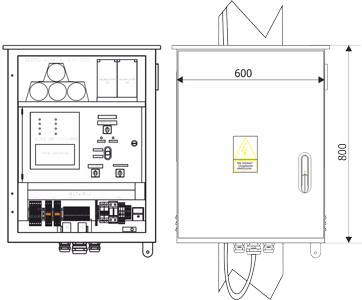
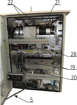
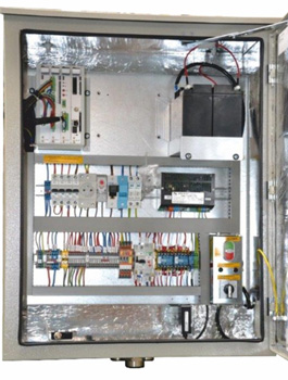
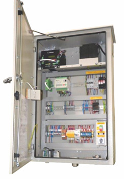
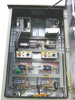
Object cabinet
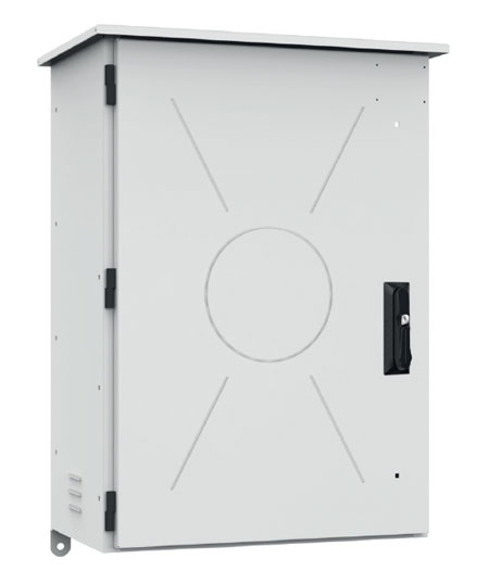
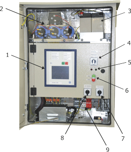
- SO type control cabinets (object cabinets) are designed for comprehensive operation of THO type remotely controlled disconnectors manufactured by ZPUE.
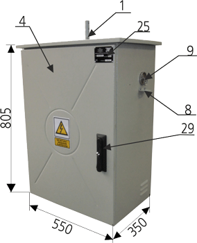
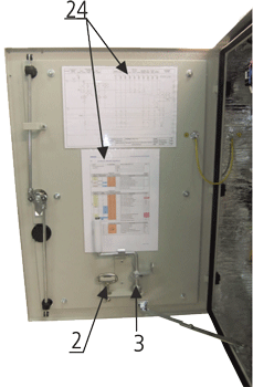
- The cabinet housing is made of powder-coated aluminium sheet (stainless steel housing is also available). The cabinet doors are equipped with a Master-Key lock with the option of adding a padlock and a lock to prevent accidental closure. The enclosure features a special drainage system that prevents dirt from getting inside. The enclosures are thermally insulated as standard.
- Metal glands are installed in the bottom of the object cabinet through which all necessary cables (control, antenna, power supply, etc.) are fed. The glands are selected according to the needs of a given investment.
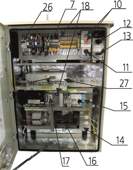
- The object cabinets provide space for the installation of commercially available telemechanics controllers and communication modems from any manufacturer that integrate the following functions: measurement, protection, motor drive control, telemechanics, automation and multi-channel disturbance recorder, as well as for collecting and processing information about network parameters and events. They ensure proper communication with the SCADA system.
- In addition to the telemechanics system, cabinets of this type are usually equipped with a 230VAC service socket, internal LED lighting, and automatic heating and exhaust fan. They can also be fitted with devices such as radio modems for the TETRA system, industrial switches, fibre optic equipment, etc.
- The exact electrical diagram and device layout depend on the standards of the relevant power company or the customer's guidelines.
- The standard colour of the aluminium enclosure coating is RAL 7035. The colour can be changed to any colour as required. We can also design and manufacture control cabinets for other disconnectors or devices according to customer specifications. Please contact us with your individual enquiry.
Choosing a wardrobe – table of symbols
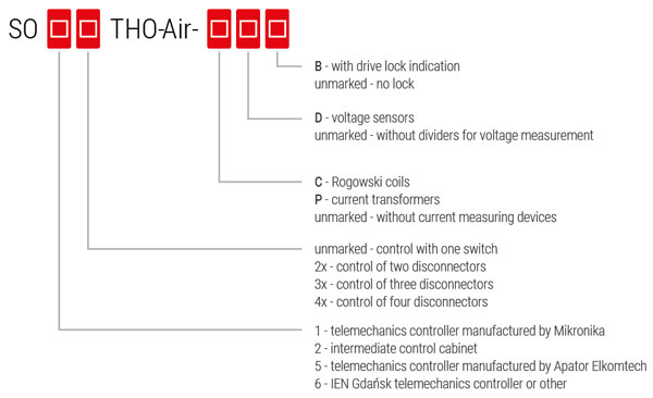
SO1-THO-Air-P-D-B - Cabinet for controlling one THO Air circuit breaker with drive lockout signalling, current transformers and voltage dividers. Telemechanics controller manufactured by Mikronika.
SO5-THO-Air-P-D-B - Cabinet for controlling one THO Air circuit breaker with drive lockout signalling, current transformers and voltage dividers. Telemechanics controller manufactured by Apator Elkomtech.
SO1-2xTHO-Air-C-D - Cabinet for controlling two THO Air disconnectors, Rogowski coils and voltage dividers. Telemechanics controller manufactured by Mikronika.
SO2-THO-Air - A small cabinet containing only the control circuits of a THO Air type disconnector. Used when the telemechanics controller is located in a separate cabinet.
SO6-THO-Air-P-D-B - Cabinet for controlling one THO Air circuit breaker with drive lockout signalling, current transformers and voltage dividers. IEN Gdańsk telemechanics controller or equivalent from another manufacturer.
Compliance with standards
- PN-EN 62271-1:2018-02 - High-voltage switchgear and controlgear - Part 1: Common provisions for alternating current switchgear and controlgear
- PN-EN IEC 61439-1:2021-10 - Low-voltage switchgear and controlgear assemblies - Part 1: General requirements
- PN-EN 60439-5:2008 - Low-voltage switchgear and controlgear assemblies - Part 5: Particular requirements for assemblies for power distribution in public networks
- PN-EN ISO 1461:2023-02 - Zinc coatings applied to steel and cast iron products by immersion
- PN-EN ISO 12944-2:2018-02 - Paints and varnishes – Protection of steel structures against corrosion by protective paint systems – Part 2: Classification of environments
- PN-EN 60529:2003 - Degrees of protection provided by enclosures (IP code) and related standards
- PN-EN 62262:2003 - Degrees of protection against external mechanical impacts provided by electrical equipment enclosures (IK code)
- PN-EN 61140:2016-07 - Protection against electric shock – Common aspects of installations and equipment
Parameters
| Parameters of object cabinets | |
| Rated voltage of the AC power supply | 230 VAC* |
| Rated voltage of internal circuits | 24/12 VDC |
| Degree of protection | IP54** |
| Ambient temperature range | -40°C +60°C |
| Possibility of installing data transmission modules | GPRS/TETRA NET-MAN/TRUNKING |
| Degree of protection against external impacts | IK10 |
| Weight | 35-50kg*** |
* Can be manufactured for other supply voltages
** Other IP ratings available depending on customer requirements
*** Weight depends on equipment variant and number of connectors supported