Motor drives type NSP-7/SO-2 and NSP-8 manufactured by ZPUE are adapted for maneuvering with switch disconnectors from the RN and RPN groups with a rotating motion (in a place where hand drives have been applied), which functionality exceeds other solutions used in the power industry. Motor drive housings are made from powder-painted aluminum sheets (it is possible to order drives in housings made from stainless steel), drive series NSP-7/SO-2 (requires a separate plant/PLC controller installed in a separate control cabinet).
Drive series NSP-8 can be equipped with a telemechanics controller manufactured by Mikronika, Elkomtech, power supply to charge the batteries, batteries, short-circuits indicator. All drives manufactured by ZPUE S.A. cooperate with all dispatch systems: Wind-ex; Syndis; NetMan-Radius; SEN-CZAT.
Motor drives T1 and T2 are dedicated to only the THO series switch disconnectors. They were described in the subchapter “Switch disconnectors “sectionalizers” THO in closed casings for Smart Grid networks.
Types of motor drives
| Types of motor drives | ||||
| Drive type | T-1 | T-2 | NSP-7-SO2 | NSP-8/ with telemechanics |
| Power supply voltage | 24 V DC | 24 V DC | 24 V DC | 230 V AC/ 24 V DC |
| Motor power | 160 W | 160 W | 330 W | 400 W |
| Start-up current consumption | 6,8 A | 6,8 A | 9 A | 20 A |
| Average time (*) of close / open switching operations | 4-6 s | close 4-6/ switch off 0,1s |
>2 s | >2 s |
| Drive weight | 27 kg | 27 kg | 38,6 kg | 65 kg |
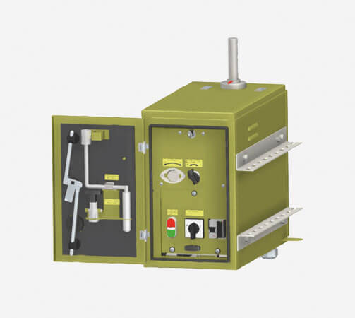
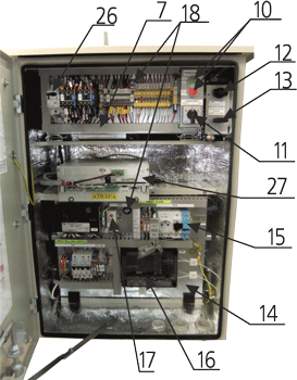
Motor drive NSP-7/SO-2
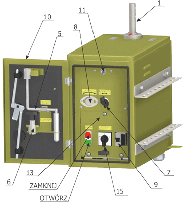
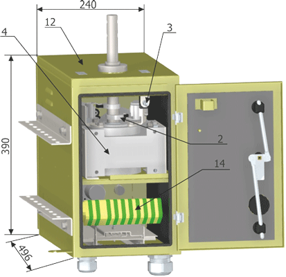
- Main shaft
- Control cam
- Limit circuit breaker
- Gearmotor
- Crank
- Manual drive mechanical interlock
- Manual drive slot interlock
- Manual drive slot
- Power supply protection
- Housing door
- Door opening indication
- Drive casing
- Control panel SO-2
- Terminal strip with signals conduction
- Control operation mode
Operating principle
NSP-7/SO-2 is an electric drive 24V DC equipped with a control panel SO-2.
The drive has a motor for 24 V DC voltage, single-step spur gear and electric control system SO-2. Switch disconnector maneuvering is performed when the main shaft drive is rotated to a 180° angle. The drive’s construction allows it to be handled from the ground level. The drive has a mechanical operation interlock, which protects against closing the drive during network operations.
A mechanical interlock allows permanent locking of the switch disconnector in the “OPEN” or “CLOSE” position. In order to lock the drive, the manual drive slot interlock (7) should be opened. Next insert the hand drive mechanical interlock (6) in such a way as to fit the interlock lugs with the cut out of the manual drive slot (8), then close the casing door (10).
Opening of the manual driver slot interlocks causes simultaneous switching off of the drive power supply thanks to the limit switch activation. Pulling out the mechanical interlock (6) from the manual drive slot (8) and closing the manual drive slot interlock (7) causes the release of the lock.
The switch disconnector can be maneuvered remotely or electrically from the control panel SO-2.
On the control cubicle panel are buttons:
"CLOSE" - send an impulse to close switch disconnector;
"OPEN” - send an impulse to open switch disconnector;
The control operation mode (15) is used to choose the way in which to control the switch disconnector:
1. REMOTE – remote control of the connector (radio control)
0. SWITCHED OFF – controlling deactivated
2. LOCAL - connector manoeuvring using buttons on the SO-2 control panel
Detailed information related to the drive is included in the DTR documentation.
Motor drive NSP-8 with telemechanics unit
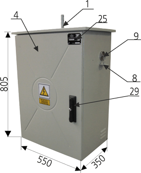
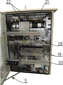
- Main shaft of the drive
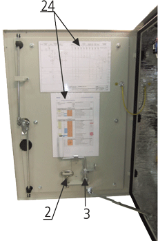
- Espagnolette key to open panels
- Manual drive crank
- Drive casing
- Door opening interlock
- Terminal to ground the drive casing
- Control panel SO-2
- Place for installation of the mechanical interlock padlock
- Manual drive slot
- Local control buttons (Close / Open)
- Control operation mode (Remote/ Deactivated/ Local)
- Manual drive lever interlock
- Manual drive interlock lever
- Assembly board with the apparatus
- Main overcurrent protection with the earthing switch disconnector Tytan (2A)
- Ahort circuit indicator SZN-1 (option related to the controller type)
- Temperature regulator
- Espagnolette lock to open panels
- Batteries
- Heater
- Gearmotor
- Limit switches of the drive shaft position indication
- Optical indicator of the shaft position (by the main shaft 1)
- Electrical diagram
- Rating plate
- Drive power supply circuit breaker 24 V DC
- Plant/PLC controller (depending on the manufacturer)
- Place for radio installation
- Lock with the padlock option
Operating principle
The NSP-8 drive is installed in powder-painted aluminum sheet casing with a thermal isolation (it can also be made from stainless steel sheet in a special order), it is additionally equipped with a lock Master Key type with the possibility of being locked with a padlock. The construction of the drive allows its operation from the ground level. The drive is fixed to the concrete pole in such a way so as to allow the combination of the main drive shaft NSP together with the switch disconnector drive crank. Rods, which join the switch disconnector with the NSP-8 drive are delivered as the drive’s equipment. The drive is equipped with a motor, single-step spur gear and electric control system.
Switch disconnector maneuvering is performed when the main shaft drive is rotated to a 180° angle.
For proper operation, the NSP-8 drive needs an external power supply of 230V from the auxiliary transformer mounted on a pole.
Moreover, the electric drive is equipped with a Plant/PLC controller manufactured by Mikronika, Elkomtech, Instytut Gdańsk, and can be additionally equipped with an underground and inter-phase short-circuit indicator, e.g. SZN-1, SZK-030/B or another type with specific dimensions.
The connection diagram of the NSP-8 drive with the controller, and a part of the assembly board are shown in the drive documentation DTR. Before performing the switching operations with the remote control or from the control panel, the operator must be familiar with the manual drive handling (in particular with the possibility of mechanical locking of the drive), which is described in detail in documentation DTR.
Switch disconnector maneuvering can be performed remotely or electrically from the control panel SO-2.
On the panel SO-2 of the control cubicle there are buttons (10):
"CLOSE” - send an impulse to close switch disconnector; "OPEN” – send an impulse to open switch disconnector;
The control operation mode (11) is used to choose the way in which to control the switch disconnector:
1. REMOTE – connector remote control (radio control)
0. SWITCHED OFF – controlling deactivated with no possibility of remote or local control
2. LOCAL - connector manoeuvring using buttons (10) on the SO-2 control panel
Detailed information related to the drive is included in documentation DTR.
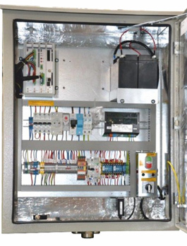
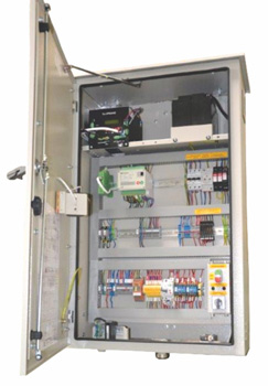
Control cabinets series SO for remote supervision of the connectors in Smart Grid networks
Control cabinets „SO” are designed for comprehensive operation of the remote controlled connectors manufactured by ZPUE. A control cabinet housing is made from powder-painted aluminum sheet. Also installed is a special drainage system, which prevents contaminants from getting inside.
The cabinet housing door is equipped with a lock type Master-Key with the possibility to install a padlock, and the interlock which prevents accidental closing. Control cabinets can be equipped with a service slot 230 V AC, internal lighting, 30 W heater and exhaust ventilator.
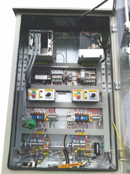
Installed at the bottom of the control cabinet are metal glands with diameters fi 36 and fi 29, which conduct control cables from the switch disconnector drive, antenna cable and auxiliary transformer power supply or other power sources (glands are individually fitted at the production stage).
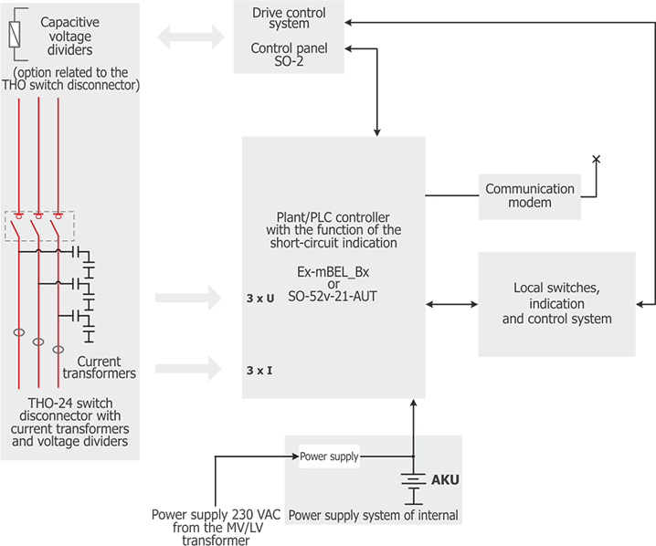
Installed In control cabinets are bay controllers type Ex-mBEL; SO-52v-21-xxx; USP-120/x and others available on the market, and communication modules of any manufacturer, which integrate the following functions: metering, protection, motor drive control, telemechanics, automatics and multi-channel fault recorder, as well as collecting information of the network parameters and events, and guarantee proper communication with the SCADA system.
A detailed functional description of the controllers and communication modules is contained in the separate controllers’ and modems’ documentation, which are available after making an enquiry to ZPUE S.A. or the manufacturer of the controller.
Compliance with standards:
- PN-EN 62271-1 - High Voltage Switchgear and Control gear – Part 1: Common specifications,
- PN-EN 61439-1:2011 - Low Voltage Switchgear and Control gear – Part 1: General specifications,
- PN-EN 60529:2003 - Degrees of protection provided by enclosures (IP code),
- PN-EN 60439-5:2008 - Low Voltage Switchgear and Control gear – Part 5: Particular requirements for assemblies for power distribution in public networks,
- PN-EN ISO 1461:2011 - Hot dip galvanized coatings on fabricated iron and steel articles,
- PN-EN ISO 12944-2:2001P - Paints and Varnishes - Corrosion protection of steel structures through the use of painting methods – Part 2: environment classification,
- PN-EN 60529: 2003 - Degrees of protection provided by enclosures (IP code) and related standards,
- PN-EN 62262:2003 - Degrees of protection against mechanical damages provided by the enclosures of the electrical devices (IK code),
- PN-EN 61140:2005/A1:2008 - Protection against electric shock - Common aspects for installation and equipment,
- PN-EN ISO 12944-2:2001P - Paints and Varnishes - Corrosion protection of steel structures through the use of painting methods – Part 2: environment classification.
| Control cabinets series SO parameters | |
| Rated voltage of the altering current power supply | 230VAC |
| Rated voltage of the internal systems power supply | 24/12VDC |
| Degree of protection | IP54 |
| Ambient temperature range | -40°C +55°C |
| Possibility to install transmission modules | GPRS/TETRA/NET-MAN/TRUNKING |
| Self-weight | 35-50kg* |
* Self-weight influenced by the equipment variant and the number of operated connectors.
Flow chart of the control cabinet „SO”
Communication with the
supervision centres
for the Smart Grid networks

Control cabinet SO1G/THO with the SO-52v-21 controller
Control cabinet SO5G/THO with the Ex-mBEL_S2 controller
Control cabinet SO1/2G/THO with the SO-52v-21-AUT controller