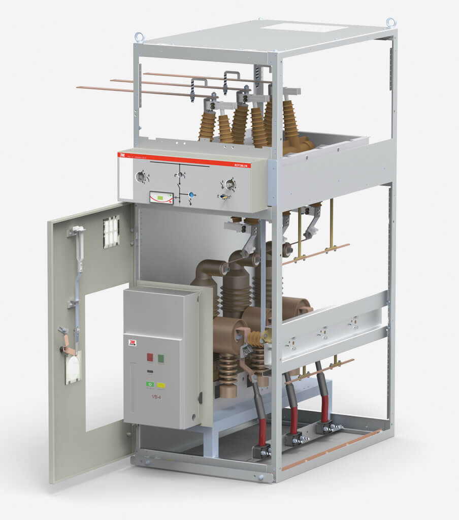
The subject of this document is a ROTOBLOK type state-of-the-art, indoor medium voltage switchgear intended for distribution of three-phase alternating current with a frequency of 50 Hz, at a rated voltage up to 24 kV, in industrial and commercial power sector distribution grids. The switchgears are configured from standard single bays with varied equipment. The information and technical data specified herein enable the designer to assemble a switchgear from typical modules. In case bays with equipment not specified herein or with changed dimensions are needed, the scope of equipment should be arranged with the manufacturer.
Construction of switchgear type Rotoblok
The design of each bay includes elements constructed with zinc-coated metal sheet, and bolted or riveted together. The construction of each bay ensures the possibility of easy assembly in any switchgear unit, and also rapid disassembly (e.g. in order to carry single bays into the station) and custom reconfiguration. Each bay may be constructed wider than its standard dimension. This solution is used when replacing older large size switchgears (e.g. Rue, M20) with a Rotoblok switchgear, when problems may occur with shifting the old cables to a new attachment point.
Each bay has two compartments, that is, the frame and the main disconnector shaft form a mechanical and electrical partition between the lower part of the switchgear and the primary busbar circuit. After opening the bay doors touching the primary busbar circuit is impossible. Each bay is equipped with a lower earthing switch (in a transformer bay it is installed under the fuse bases).
Each bay has a system of mechanical interlocks, which fulfils two primary tasks:
- prevents opening the door of any compartment before its power supply is switched off and the earthing switch is closed; therefore it prevents electric shock,
- forces the proper sequence of the switching operations.
Capacitive voltage dividers used in the bays allow checking for lack of voltage, and safe phase testing from the front side of the bay, in a safe manner, using a LV bipolar indicator without needing to open the bay doors. Additionally, inspection windows installed in the doors allow the observation of each element in the bay, for example: open circuits, condition of transformers, chambers, connections, etc.
An auxiliary circuits compartment is located at the top of the circuit breaker bay, used to install such elements as: terminal strips, relays, batteries, additional (or primary) protection modules, etc.
Switching devices
The main devices used in the aforementioned bays include:
- GTR1, GTR 2, GTR 2V type switch disconnectors (ZPUE)
- GTR 4, GTR 4W type disconnectors (ZPUE)
- circuit breakers by leading manufacturers
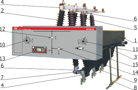
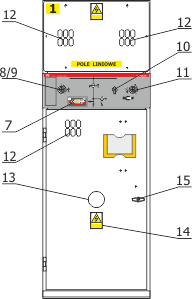
1 - galvanized steel frame
2,3 - resin insulators
4 - fixed contacts
5 - primary isolating shaft
6 - mobile contacts
7 - arc-quenching contact
8 - lower grounding switch
9 - grounding switch contact
10 - switch disconnector socket
11 - grounding switch socket
12 - switch disconnector position indicator
13 - voltage indicator
14 - grounding switch position indicator
15 - door interlock leaver
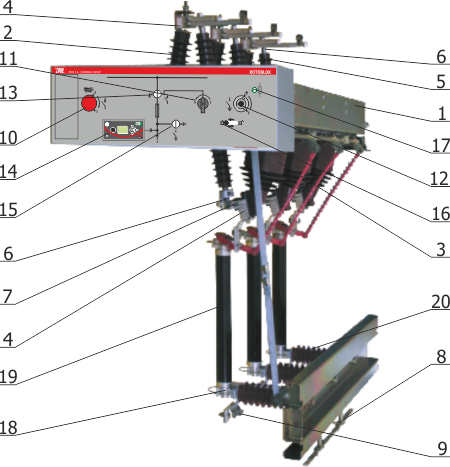
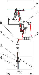
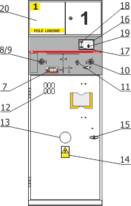
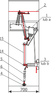
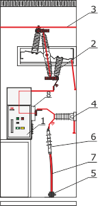
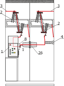
1 - zinc-coated steel frame
2,3 - resin insulators
4 - fixed contacts
5 - main insulating shaft
6 - moving contacts
7 - arcing moving contact
8 - lower earthing switch
9 - earthing switch contact
10 - charging socket and charging indicator
11 - “on”/“off” switch
12 - earthing switch socket
13 - switch disconnector position indicator
14 - voltage indicator
15 - earthing switch position indicator
16 - door interlock lever
17 - fuse link position indicator
18 - fuse base
19 - fuse link
20 - post insulator or capacitive voltage divider
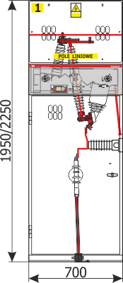
Line feederwith manual drive
| Standard equipment | |||
| Device name | Type | Amount | |
| 1. | Switch disconnector with a lower earthing switch | GTR 1 or GTR 2 | 1 |
| 2. | Busbar circuit | P 40x5 / P 40x10 | 3 |
| 3. | Capacitive voltage divider | 3 | |
| 4. | Cable clamp | UKZ | 3 |
| 5. | Cable termination | 3 | |
| 6. | Cable | 3 | |
| 7. | Neon voltage indicator operating with the capacitive voltage divider | 1 | |
| 8. | Switch disconnector socket (for GTR 1) | 1 | |
| 9. | Charging socket and indicator (for GTR 2) | 1 | |
| 10. | “On”/“off” switch (for GTR 2) | 1 | |
| 11. | Earthing switch socket | 1 | |
| 12. | Inspection window | 1 | |
| 13. | Window which allows the use of a torch to check the position of contacts in case of a lighting failure |
3 | |
| 14. | Warning plate | 1 | |
| 15. | Door handle | 1 | |
| Additional equipment at the customer's request | ||
| a | Short-circuit current indicator attached by cable | 1 |
| b | Short-circuit current indicator attached by busbar | 3 |
Line feeder with motor drive


| Standard equipment | |||
| Device name | Type | Amount | |
| 1. | Switch disconnector with a lower earthing switch and motor drive adapted for remote control via cables or via radio | GTR 1M or GTR 2M | 1 |
| 2. | Busbar circuit | P 40x5 / P 40x10 | 3 |
| 3. | Capacitive voltage divider | 3 | |
| 4. | Cable clamp | UKZ | 3 |
| 5. | Cable termination | 3 | |
| 6. | Cable | 3 | |
| 7. | Neon voltage indicator operating with the capacitive voltage divider | 1 | |
| 8. | Switch disconnector socket (for GTR 1M) | 1 | |
| 9. | Charging socket and indicator (for GTR 2M) | 1 | |
| 10. | “On”/“off” switch (for GTR 2M) | 1 | |
| 11. | Earthing switch socket | 1 | |
| 12. | Inspection window | 1 | |
| 13. | Window which allows the use of a torch to check the position of contacts in case of a lighting failure | 3 | |
| 14. | Warning plate | 1 | |
| 15. | Door handle | 1 | |
| 16. | Control panel for motor drive | 1 | |
| 17. | “Close” button | 1 | |
| 18. | “Open” button | 1 | |
| 19. | Operation mode selection switch | 1 | |
| 20. | Auxiliary circuits compartment | 1 | |
| Additional equipment at the customer's request | ||
| a | Short-circuit current indicator attached by cable | 1 |
| b | Short-circuit current indicator attached by busbar | 3 |
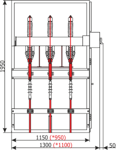
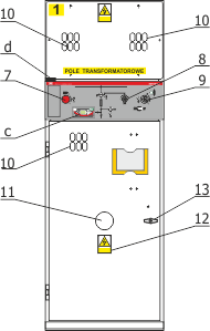
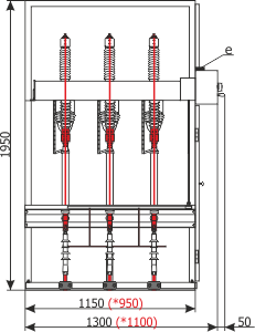
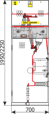
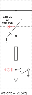
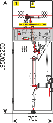
Transformer feeder design
| Standard equipment | |||
| Device name | Type | Amount | |
| 1. | Fuse switch disconnector with earthing switch | GTR 2V | 1 |
| 2. | Busbar circuit | P 40x5 / P 40x10 | 3 |
| 3. | Post insulator | 3 | |
| 4. | Cable clamp | UKZ | 3 |
| 5. | Cable termination | 3 | |
| 6. | Cable | 3 | |
| 7. | Charging socket and indicator | 1 | |
| 8. | “On”/“off” switch | 1 | |
| 9. | Earthing switch socket | 1 | |
| 10. | Inspection window | 1 | |
| 11. | Window which allows the use of a torch to check the position of contacts in case of a lighting failure | 3 | |
| 12. | Warning plate | 1 | |
| 13. | Door handle | 1 | |
| 14. | Fuse base which forms an integral part of the switch disconnector | 1 | |
| 15. | Fuse link | 1 | |
| Additional equipment at the customer's request | |||
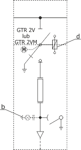
| a | Fuse switch disconnector with earthing switch and motor drive | GTR 2VM | 1 |
| b | Capacitive voltage divider | 3 | |
| c | Neon voltage indicator operating with the capacitive voltage divider | 1 | |
| d | Tripping coil | 1 | |
| e | Gland for cable entry with the use of a tripping coil | 1 | |
| Note! The earthing switch in the switch disconnector earths the lower part of the fuse link. |
|||
Tripping coil operation in a transformer bay with gas-flow protection or thermal protection of the transformer
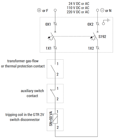
Note!
Cable cross-section and protection currents should be selected according to the tripping coil supply voltage.
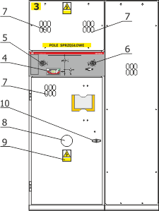
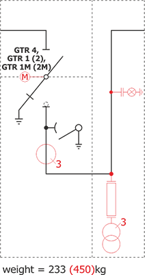
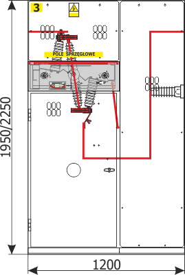
Bus coupler unit design
| Standard equipment | |||
| Device name | Type | Amount | |
| 1. | Disconnector with a lower earthing switch | GTR 4 | 1 |
| 2. | Busbar circuit | P 40x5 / P 40x10 | 3 |
| 3. | Post insulator or capacitive voltage divider | 3 | |
| 4. | Neon voltage indicator operating with the capacitive voltage divider | 1 | |
| 5. | Disconnector socket | 1 | |
| 6. | Earthing switch socket | 1 | |
| 7. | Inspection window | 1 | |
| 8. | Window which allows the use of a torch to check the position of contacts in case of a lighting failure | 3 | |
| 9. | Warning plate | 1 | |
| 10. | Door handle | 1 | |
| Additional equipment at the customer's request | |||
| a | Switch disconnector with a lower earthing switch | GTR 2 | 1 |
| b | Switch disconnector with a lower earthing switch and motor drive | GTR 1M or GTR 2M | 1 |
| Note! The construction of a bus coupler bay without a lower earthing switch is possible |
|||
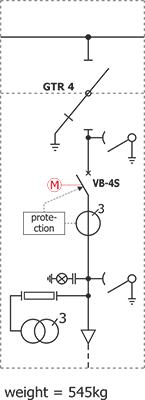
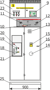
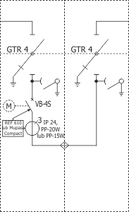
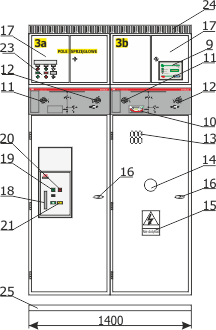
Desing of transformer feeder type RWT
| Standard equipment | |||
| Device name | Type | Amount | |
| 1. | Circuit breaker | 1 | |
| 2. | Disconnector with a lower earthing switch | GTR 4 | 1 |
| 3. | Busbar circuit | P 40x5 / P 40x10 | 3 |
| 4. | Capacitive voltage divider | 3 | |
| 5. | Cable clamp | UKZ | 3 |
| 6. | Cable termination | 3 | |
| 7. | Cable | 3 | |
| 8. | Current transformer operating with the protection system | IP 24 / PP-20W / PP-15W | 3 |
| 9. | Protection system | Mupasz / REF MiCOM | 1 |
| 10. | Neon voltage indicator operating with the capacitive voltage divider | 1 | |
| 11. | Disconnector socket | 1 | |
| 12. | Earthing switch socket | 1 | |
| 13. | Inspection window | 1 | |
| 14. | Window which allows the use of a torch to check the position of contacts in case of a lighting failure | 1 | |
| 15. | Warning plate | 1 | |
| 16. | Door handle | 1 | |
| 17. | Auxiliary circuits compartment | 1 | |
| 18. | Charging socket | 1 | |
| 19. | “ON” button | 1 | |
| 20. | “OFF” button | 1 | |
| 21. | Charging indication | 1 | |
| 23. | Control switches and lamps | 1 | |
| 24. | Cable tray | 1 | |
| 25. | Load-bearing frame | 1 | |
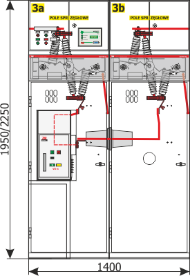
Desing of bus cupler unit type RWS
| Standard equipment | |||
| Unit | Type | Amount | |
| 1. | Circuit breaker | 1 | |
| 2. | Disconnector with a lower earthing switch | GTR 4 | 1 |
| 3. | Busbar circuit | P 40x5 / P 40x10 | 3 |
| 4. | Capacitive voltage divider | 3 | |
| 8. | Current transformer operating with the protection system | IP 24 / PP-20W / PP-15W | 3 |
| 9. | Protection system | Mupasz / REF MiCOM | 1 |
| 10. | Neon voltage indicator operating with the capacitive voltage divider | 1 | |
| 11. | Disconnector socket | 1 | |
| 12. | Earthing switch socket | 1 | |
| 13. | Inspection window | 1 | |
| 14. | Window which allows the use of a torch to check the position of contacts in case of a lighting failure | 1 | |
| 15. | Warning plate | 1 | |
| 16. | Door handle | 1 | |
| 17. | Auxiliary circuits compartment | 1 | |
| 18. | Charging socket | 1 | |
| 19. | „ON” button | 1 | |
| 20. | „OFF” button | 1 | |
| 21. | Charging indication | 1 | |
| 23. | Control switches and lamps | 1 | |
| 24. | Cable tray | 1 | |
| 25. | Load-bearing frame | 1 | |
| 26. | Insulating bushing | 1 | |
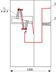
Construction method for a cable duct under the Rotoblok type MV switchgears
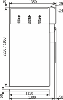
Figures 1, 2, 3 present a cable duct construction proposal. The cable bending radius (which depends on its outside diameter, according to PBUE) should taken into account when establishing the dry and oil cables duct depth. It is possible to avoid or reduce the depth of the cable duct by using a raised base or a raised floor.
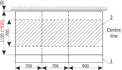
Note!: Minimum distance from the wall 30 mm
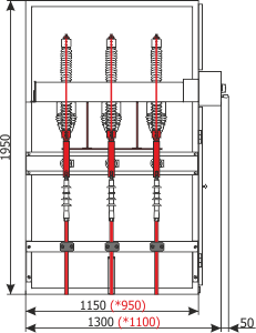
1) Example bays with a width of 700, 700, 900 mm (respectively, from the left)
2) Duct under the switchgear.
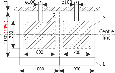
* - Rotoblok 17,5 kV switchgear depth
Note!: Minimum distance from the wall 30 mm
1) Example bays with a width of 1000, 900 mm (respectively, from the left)
2) Duct under the switchgear.
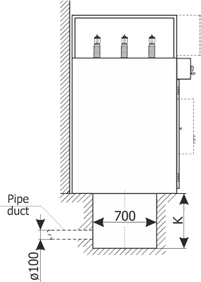
| Cable cross-section (mm2) | Bending radius (mm) | Duct depth K (mm) |
| 50 | 370 | 400 |
| 70 | 400 | 430 |
| 95 | 440 | 470 |
| 120 | 470 | 500 |
| 150 | 500 | 550 |
| 185 | 540 | 600 |
| 240 | 590 | 700 |
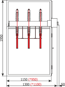
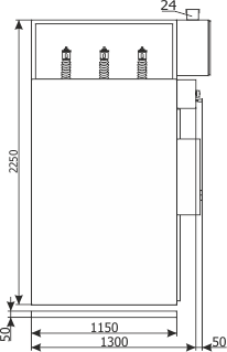
Various types of Rotoblok switchgear units
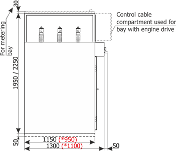
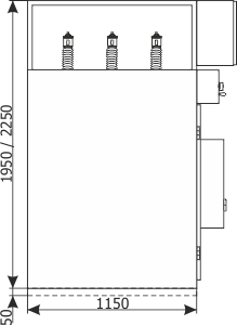
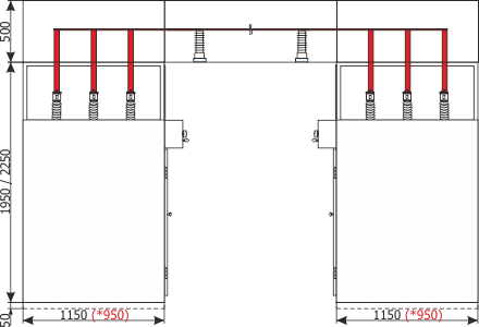
* - Rotoblok switchgear 17,5 kV depth
Note:
Figures shown on subsequent pages are only an example of bay equipment. It is possible to adapt the bay configuration to specific requirements of the end user. In this case manufacturer should be asked to provide drawings.
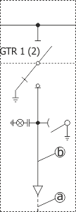
RL1 (line feeder)
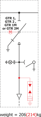
Note:
Optional equipment was marked with red on the electrical diagram.
1) It is possible to design the unit in mirrored version
2) It is possible to design the bus coupler unit without a lower earthing switch
RL4 (line feeder with metering)
Note:
Optional equipment was marked with red on the electrical diagram.
1) It is possible to design the unit in mirrored version
2) It is possible to design the bus coupler unit without a lower earthing switch
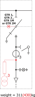
RT1 (transformer feeder)
Note:
Optional equipment was marked with red on the electrical diagram.
1) It is possible to design the unit in mirrored version
2) It is possible to design the bus coupler unit without a lower earthing switch
RS1L1) (bus coupler unit with disconnector or switch disconnector on the left side)
Note:
Optional equipment was marked with red on the electrical diagram.
1) It is possible to design the unit in mirrored version
2) It is possible to design the bus coupler unit without a lower earthing switch
RS4 (bus coupler unit with disconnector or switch disconnector on the left side)
Note:
Optional equipment was marked with red on the electrical diagram.
1) It is possible to design the unit in mirrored version
2) It is possible to design the bus coupler unit without a lower earthing switch
RP1 (metering unit)
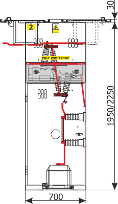
Note:
Optional equipment was marked with red on the electrical diagram.
1) It is possible to design the unit in mirrored version
2) It is possible to design the bus coupler unit without a lower earthing switch
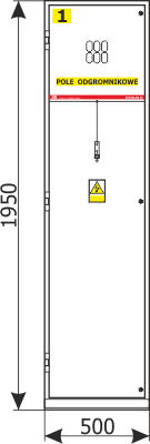
RO1 (lightning arrester unit)
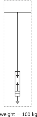
Note:
Optional equipment was marked with red on the electrical diagram.
1) It is possible to design the unit in mirrored version
2) It is possible to design the bus coupler unit without a lower earthing switch
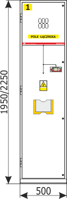
RŁ2 (Incoming cable-connection feeder)
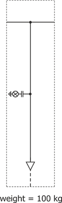
Note:
Optional equipment was marked with red on the electrical diagram
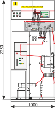
Rtpwł4 (auxiliary transformer unit)
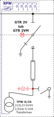
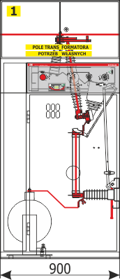
Note:
Optional equipment was marked with red on the electrical diagram
RTpwł 25kVA + RT1 (auxiliary transformer unit - max. power 25 kVA)
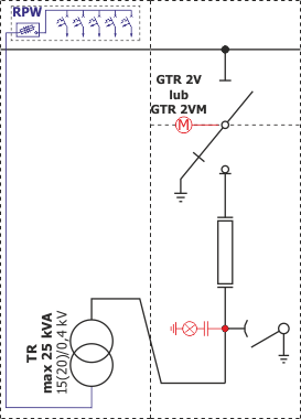
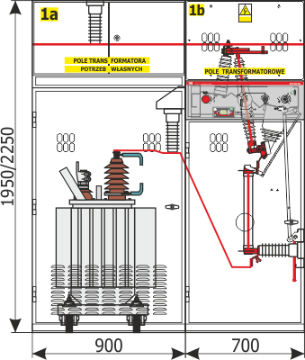
Note:
Optional equipment was marked with red on the electrical diagram
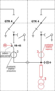
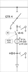
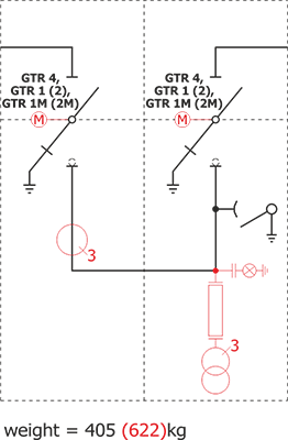
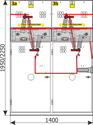
RWT (circuit breaker transformer bay)
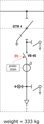
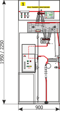
Note:
Optional equipment was marked with red on the electrical diagram
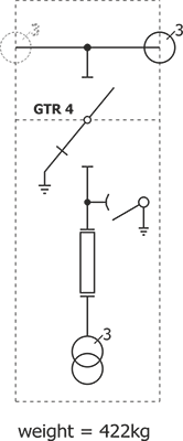
RWT3 (circuit breaker transformer feeder)
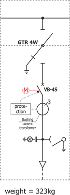
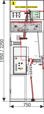
Note:
Optional equipment was marked with red on the electrical diagram