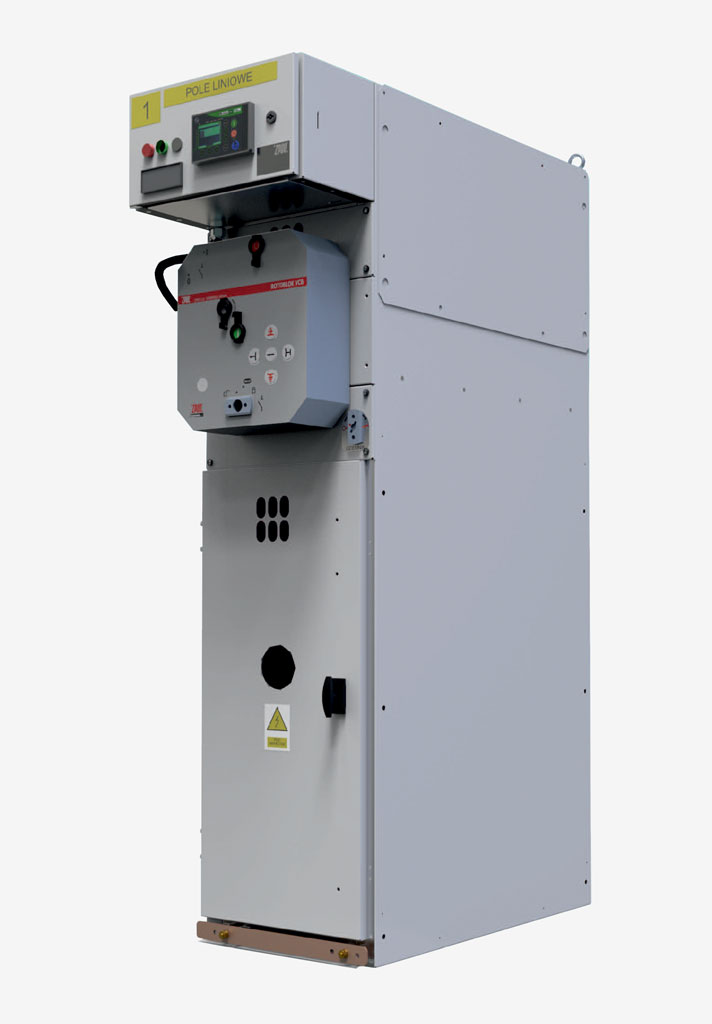
Modern, indoor medium voltage switchgear intended for distribution of three-phase alternating current with a frequency of 50 Hz, at a rated voltage up to 25 kV, in industrial and commercial power sector distribution grids. The modular design of the Rotoblok VCB switchgear bays enables and allows any configuration and combination with the Rotoblok and Rotoblok SF switchgear bay product range.
View of the switch
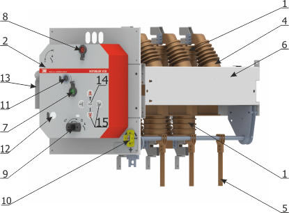
1 - Insulating main shaft with circuit breaker
2 - Switch drive
3 - Vacuum chamber of the circuit breaker
4 - Resin insulators
5 - Lower earthing switch
6 - Zinc-coated steel frame
7 - Circuit breaker ON button
8 - Circuit breaker OFF button
9 - Disconnector socket
10 - Earthing switch socket and indication
11 - Circuit breaker spring charging socket
12 - Spring charging indication
13 - Plug connections for secondary circuits
14 - Circuit breaker position indicator
15 - Disconnector position indicator
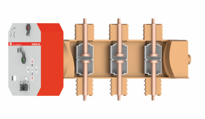
Device operating positions
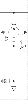
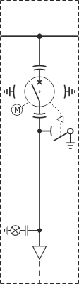
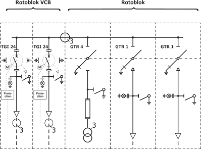
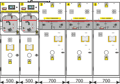
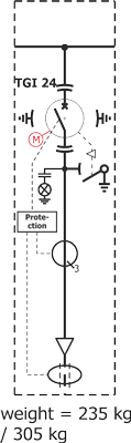
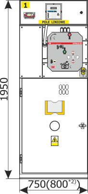
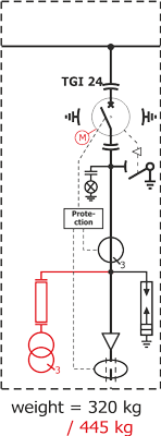
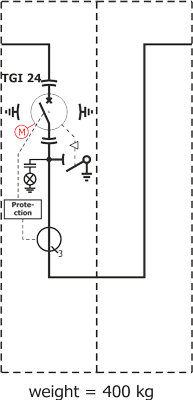
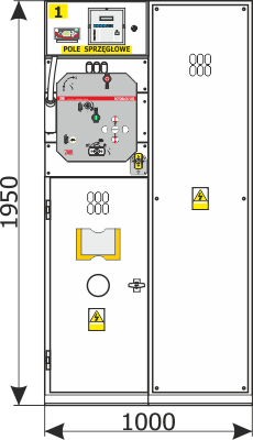
Rotoblok VCB switchgear bay variants
VCB 1
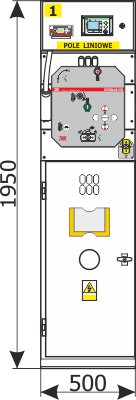
Note:
These pictures present exemplary bay equipment. It is possible to configure the bays to the customer’s needs. In such cases, please contact the manufacturer to request pictures.
Optional equipment is marked with red.
- Using 24 kV supportive current transformers instead of bushing transformers.
- Using a fuse base above the voltage transformers.
- Using voltage transformers.
- A TGI 24 apparatus with current transformers can be located on the right side of the bay.
- When the Rotoblok VCB bays are connected with Rotoblok 17,5 kV and Rotoblok SF bays, the height of the switchgear bay is 1950mm, and the depth is 950 mm. When the Rotoblok VCB bays are connected with Rotoblok 24 bays, the height of the switchgear bay is 1950 mm, and depth 1150 mm.
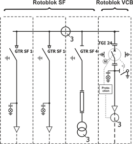
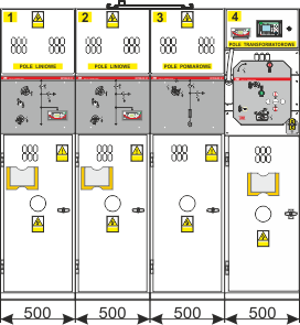
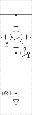
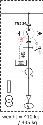
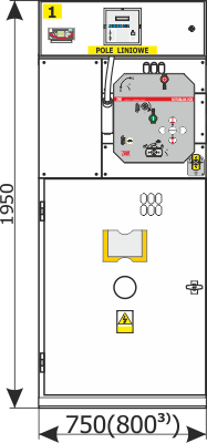
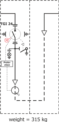
VCB 2(31))
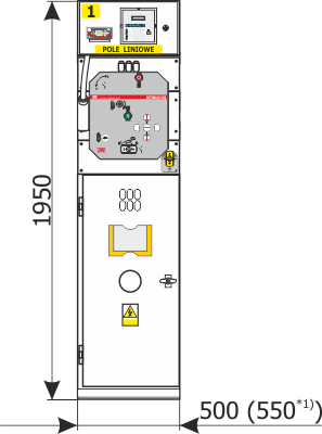
Note:
These pictures present exemplary bay equipment. It is possible to configure the bays to the customer’s needs. In such cases, please contact the manufacturer to request pictures.
Optional equipment is marked with red.
- Using 24 kV supportive current transformers instead of bushing transformers.
- Using a fuse base above the voltage transformers.
- Using voltage transformers.
- A TGI 24 apparatus with current transformers can be located on the right side of the bay.
- When the Rotoblok VCB bays are connected with Rotoblok 17,5 kV and Rotoblok SF bays, the height of the switchgear bay is 1950mm, and the depth is 950 mm. When the Rotoblok VCB bays are connected with Rotoblok 24 bays, the height of the switchgear bay is 1950 mm, and depth 1150 mm.
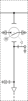
VCB 5(6*2))
Note:
These pictures present exemplary bay equipment. It is possible to configure the bays to the customer’s needs. In such cases, please contact the manufacturer to request pictures.
Optional equipment is marked with red.
- Using 24 kV supportive current transformers instead of bushing transformers.
- Using a fuse base above the voltage transformers.
- Using voltage transformers.
- A TGI 24 apparatus with current transformers can be located on the right side of the bay.
- When the Rotoblok VCB bays are connected with Rotoblok 17,5 kV and Rotoblok SF bays, the height of the switchgear bay is 1950mm, and the depth is 950 mm. When the Rotoblok VCB bays are connected with Rotoblok 24 bays, the height of the switchgear bay is 1950 mm, and depth 1150 mm.
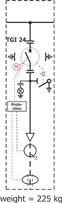
VCB O5
Notice:
These pictures present exemplary bay equipment. It is possible to configure the bays to the customer’s needs. In such cases, please contact the manufacturer to request pictures.
Optional equipment is marked with red.
- Using 24 kV supportive current transformers instead of bushing transformers.
- Using a fuse base above the voltage transformers.
- Using voltage transformers.
- A TGI 24 apparatus with current transformers can be located on the right side of the bay.
- When the Rotoblok VCB bays are connected with Rotoblok 17,5 kV and Rotoblok SF bays, the height of the switchgear bay is 1950mm, and the depth is 950 mm. When the Rotoblok VCB bays are connected with Rotoblok 24 bays, the height of the switchgear bay is 1950 mm, and depth 1150 mm.
VCB S1L(P4))

Note:
These pictures present exemplary bay equipment. It is possible to configure the bays to the customer’s needs. In such cases, please contact the manufacturer to request pictures.
Optional equipment is marked with red.
- Using 24 kV supportive current transformers instead of bushing transformers.
- Using a fuse base above the voltage transformers.
- Using voltage transformers.
- A TGI 24 apparatus with current transformers can be located on the right side of the bay.
- When the Rotoblok VCB bays are connected with Rotoblok 17,5 kV and Rotoblok SF bays, the height of the switchgear bay is 1950mm, and the depth is 950 mm. When the Rotoblok VCB bays are connected with Rotoblok 24 bays, the height of the switchgear bay is 1950 mm, and depth 1150 mm.
VCB S3L(P4))
Note:
These pictures present exemplary bay equipment. It is possible to configure the bays to the customer’s needs. In such cases, please contact the manufacturer to request pictures.
Optional equipment is marked with red.
- Using 24 kV supportive current transformers instead of bushing transformers.
- Using a fuse base above the voltage transformers.
- Using voltage transformers.
- A TGI 24 apparatus with current transformers can be located on the right side of the bay.
- When the Rotoblok VCB bays are connected with Rotoblok 17,5 kV and Rotoblok SF bays, the height of the switchgear bay is 1950mm, and the depth is 950 mm. When the Rotoblok VCB bays are connected with Rotoblok 24 bays, the height of the switchgear bay is 1950 mm, and depth 1150 mm.