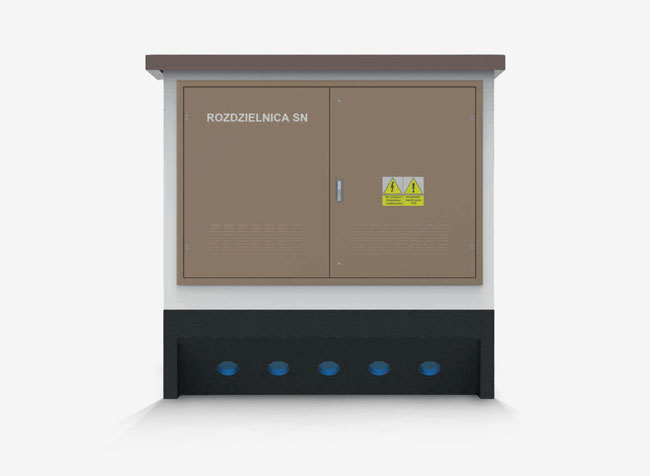
Connection box in concrete enclosure with external servicing, ZK-SN type is intended for free-standing placement and adapted to work with medium voltage underground grids or underground and overhead grids, in a ring or star system.
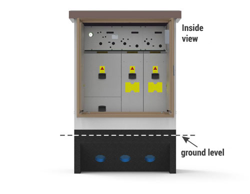
The ZN-SN enclosure is composed of two monolithic elements main structure — constructed with C30/37 class reinforced concrete, roof — constructed with C30/37 class reinforced concrete, The central element of the connection box is a TPM type MV switchgear in SF6 insulation placed inside the enclosure, which is operated from the outside, after opening the metal doors. The foundation part of the connection box is made of concrete, with process openings for feeding the cables (placed below the MV switchgear). Heads made by all leading manufacturers (CELLPACK, Euromold, Raychem etc.) may be connected to the switchgear.
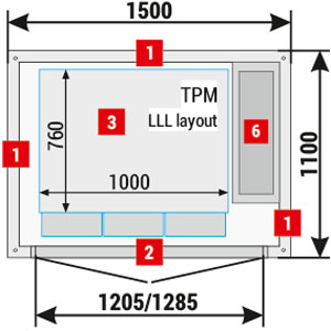
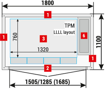
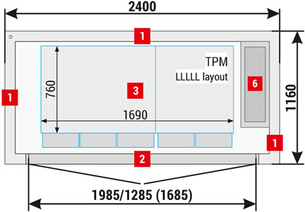
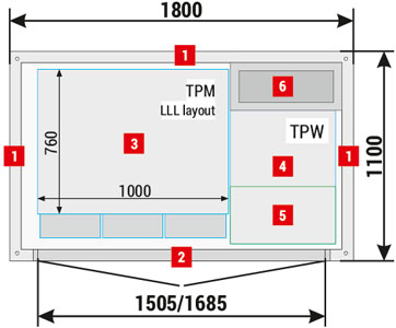
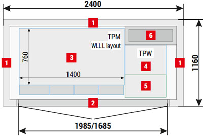
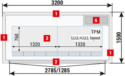
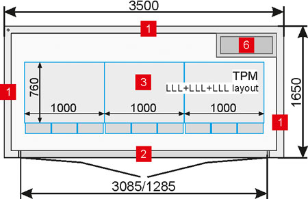
Placement of equipment - options without TPW**
| 1 | Walls, 60 mm thick — length 1500 and 1800 mm |
| Walls, 90 mm thick — length 2400, 3000, 3200 and 3500 mm | |
| 2 | Doors: solid or with ventilation louvres, without fire integrity class IP 23D - standard |
| 3 | MV switchgear |
Note!
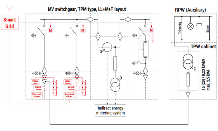
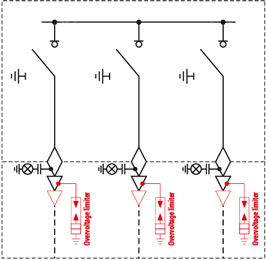
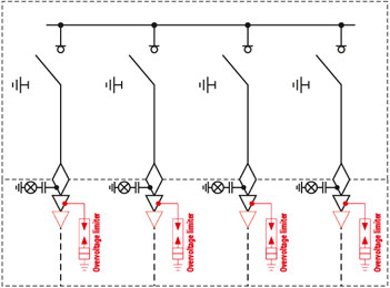
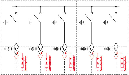
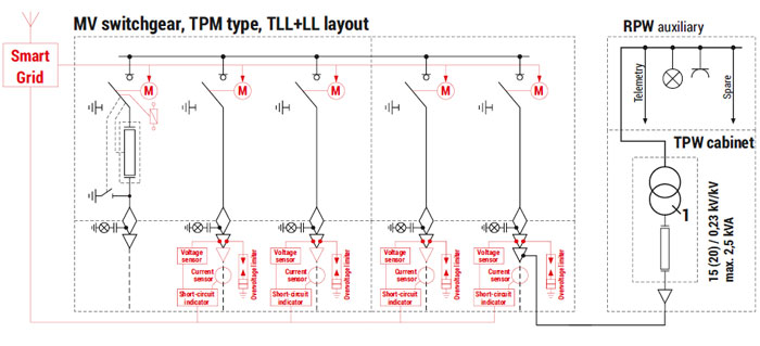
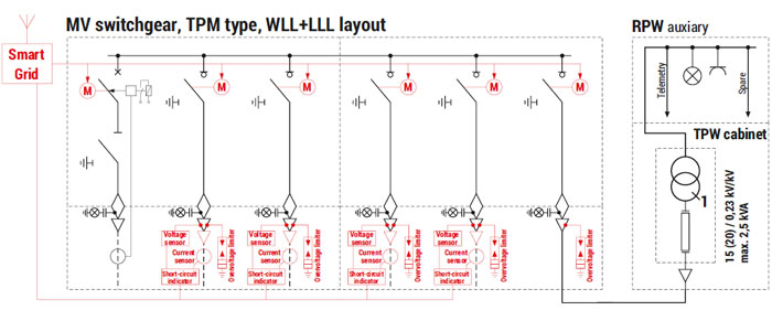
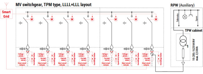
Optional equipment was marked with red on the electrical diagram.
The catalogue presents example connection box and MV switchgear configurations.
* Detailed selection of MV switchgears and their equipment is listed in chapters dedicated to individual devices in the catalogue.
** TPW — auxiliary transformer used to supply the remote control and monitoring systems.
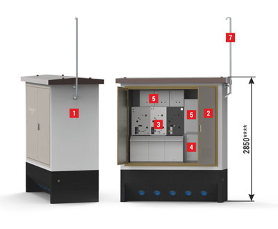
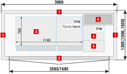
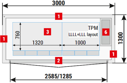
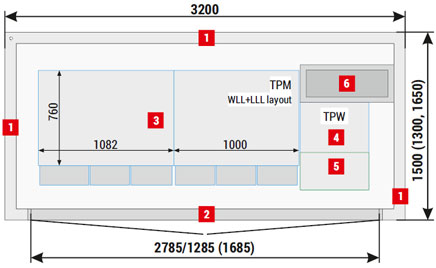
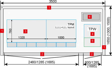
Placement of equipment — example solutions for options with TPW**
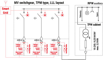
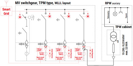
ZK-SN connection boxes do not serve only distribution purposes in a power grid. Equipped with modern, compact MV switchgears with remote monitoring and control systems, current and voltage sensors and connected short-circuit indicators, they enable cutting off damaged sections of the grid and shortening the time of power supply interruptions for the customers. This undoubtedly has a direct impact on the quality of services provided by distribution companies, which translates directly into user satisfaction.
In order to enable such functionality, the connection boxes have to be equipped with auxiliary systems supplied from an independent auxiliary transformer, supplied in turn by the MV switchgear. This solution is dedicated to Smart Grid systems, and fits perfectly in the market trends of power grid development and modernisation.
| 1 | Walls, 60 mm thick — length 1500 and 1800 mm |
| Walls, 90 mm thick — length 2400, 3000, 3200 and 3500 mm | |
| 2 | Doors: solid or with ventilation louvres, without fire integrity class IP 43 - standard |
| 3 | MV switchgear |
| 4 | TPW - auxiliary transformer cabinet |
| 5 | AMI cabinet / Smart Grid / telemetry / auxiliary |
| 6 | Gas cooler |
| 7 | Smart Grid antennas mast for GSM/TETRA system |
Note!
Optional equipment was marked with red on the electrical diagram.
The catalogue presents example connection box and MV switchgear configurations.
* Detailed selection of MV switchgears and their equipment is listed in chapters dedicated to individual devices in the catalogue. The possibility of installing other types and configurations of switchgears should be arranged every time with the connection box manufacturer.
** TPW — auxiliary transformer used to supply the remote control and monitoring systems. TPW cabinet in arc-protection design.
*** RPW — auxiliary switchgear.
**** Due to the installation of TPW, auxiliary power supply, telemetry cabinets, short-circuit indicators etc., the height of Smart Grid adapted connection boxes is higher than standard, and amounts to 2850 mm.
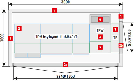
Option with voltage measurement and TPW
The main element of the connector equipment in the variant with measurement and TPW is MV switchgear in SF6 insulation, TPM type, with a built-in measuring field and a metering system (independent access from the outside). Such a solution offers new possibilities for the configuration of the MV network, as well as the construction of subscriber stations, to which free access may be difficult or even impossible (plot ownership, only remote monitoring of facilities or strategic facilities). It enables distribution and settlement companies to have full control over the measurement system, increasing the quality of their services and user satisfaction.
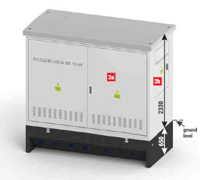
| 1 | Walls, 90 mm thick - standard |
| 2a | MV switchgear compartment doors, solid or with ventilation louvres, without fire integrity class IP 43 - standard |
| 2b | Metering panel doors, solid without fire integrity class IP 43 - standard |
| 3 | MV switchgear |
| 4 | TPW - auxiliary transformer cabinet |
| 5 | AMI cabinet / Smart Grid / telemetry / auxiliary |
| 6 | Gas blow-out system |
| 7 | Metering panel |
| Height of the main structure [mm] | 2850 |
| Usable area [m2] | 3,72 |
| Total weight with roof [kg] | 6500 |