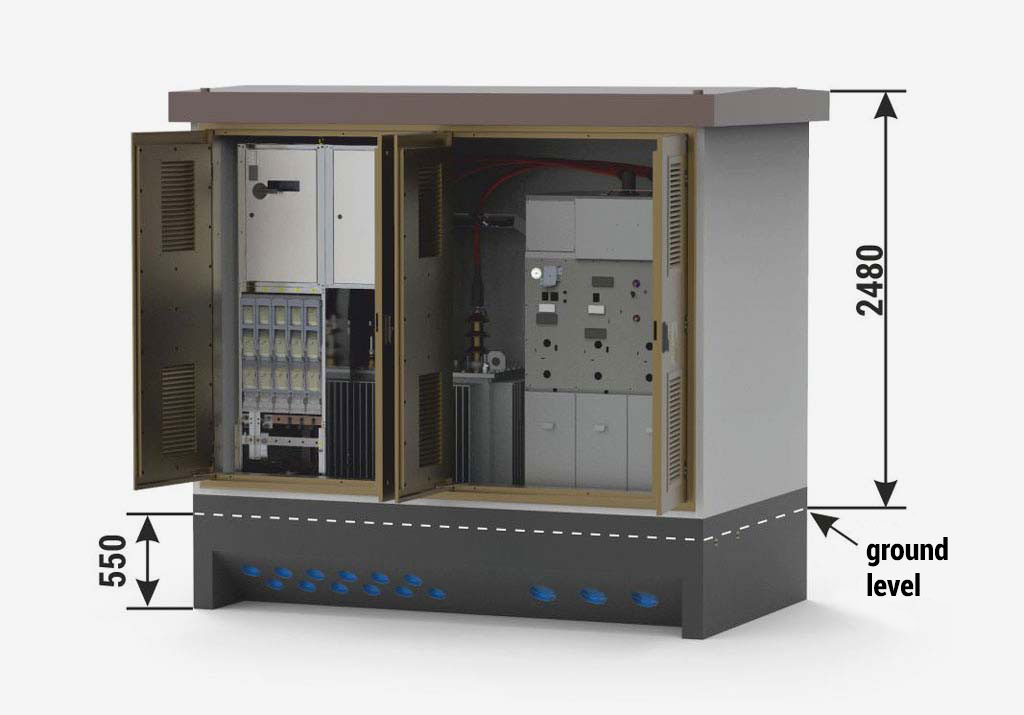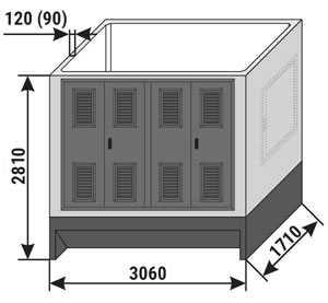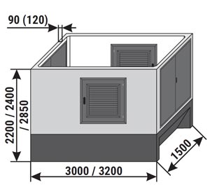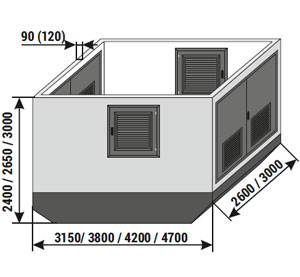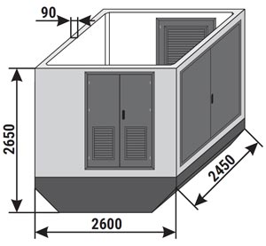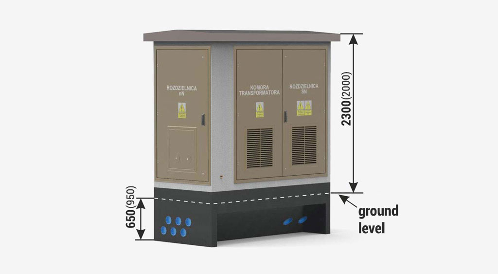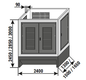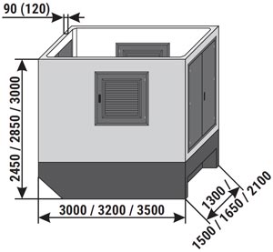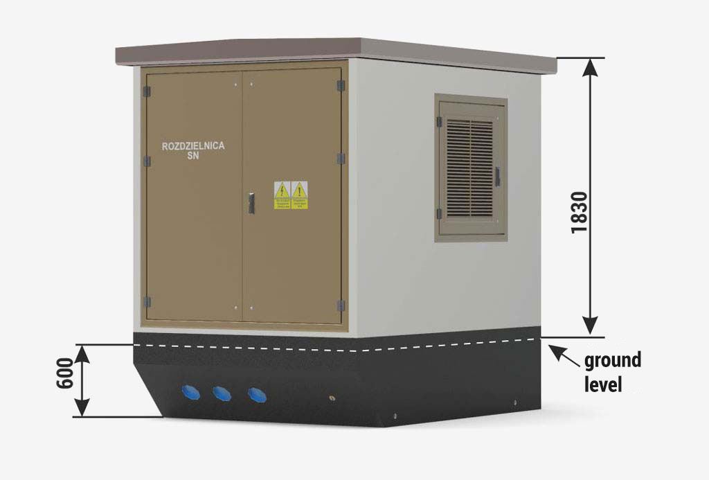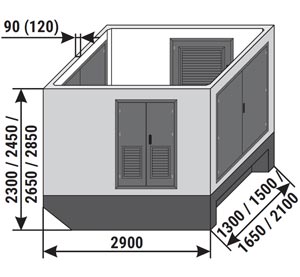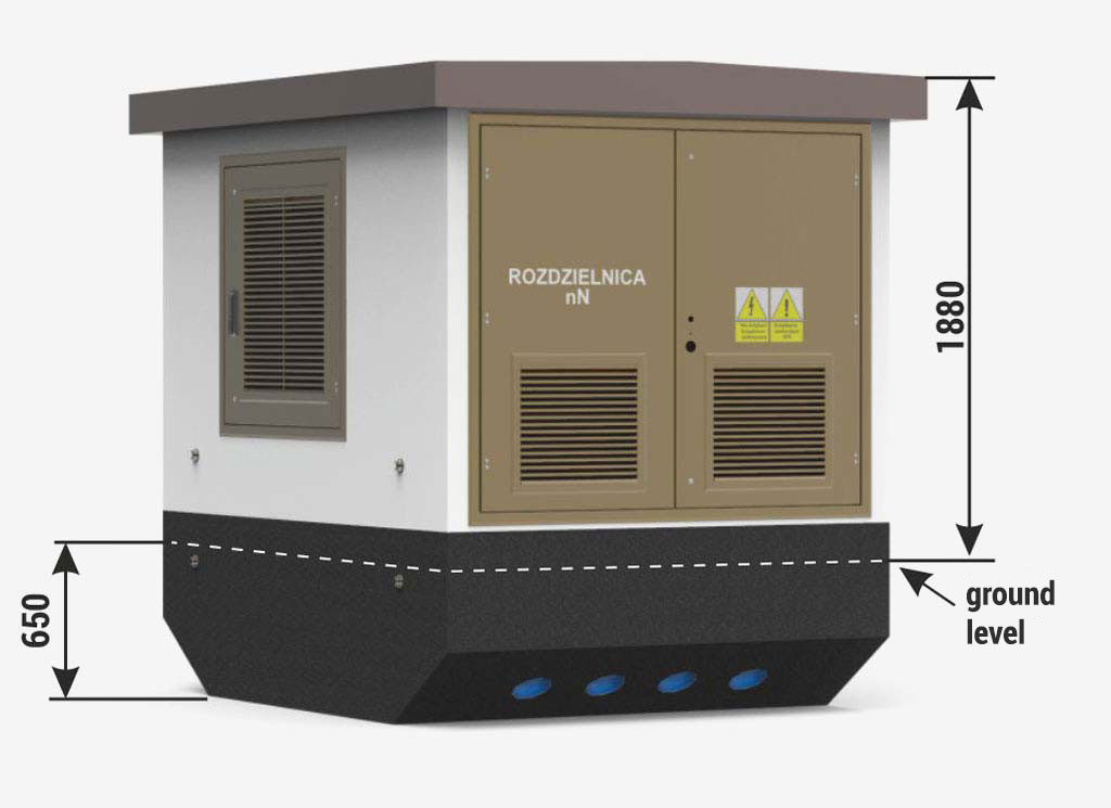
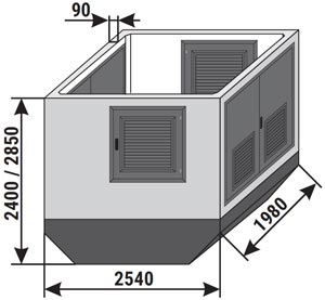
| Height of the main structure of the substation: | |
| Standard | 2400 mm |
| Optional | 2850 mm |
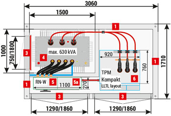
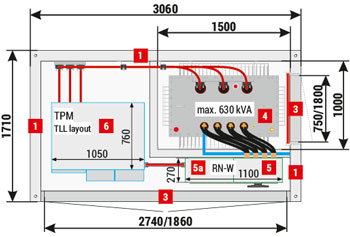
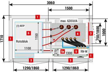
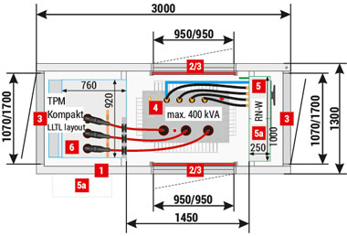
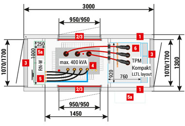
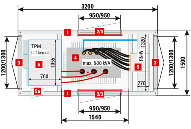
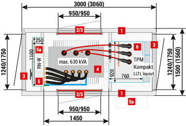
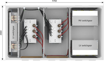
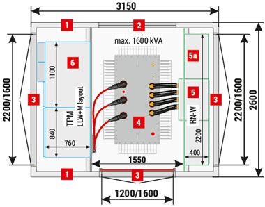
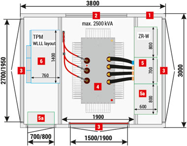
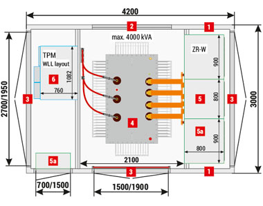
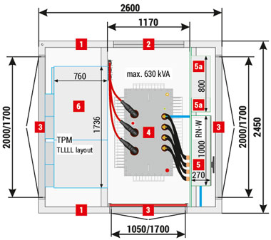
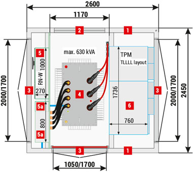
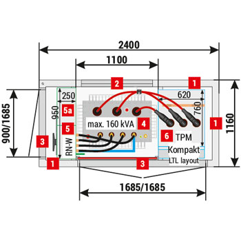
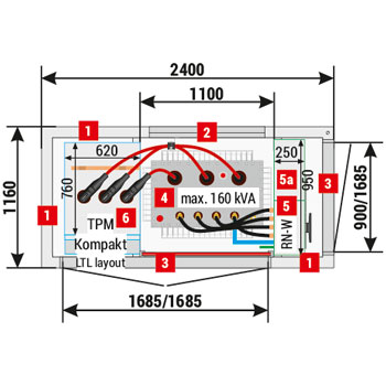
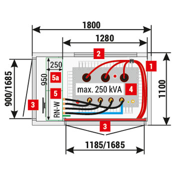
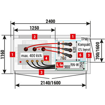
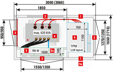
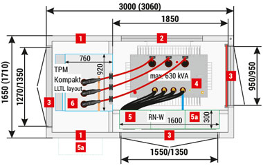
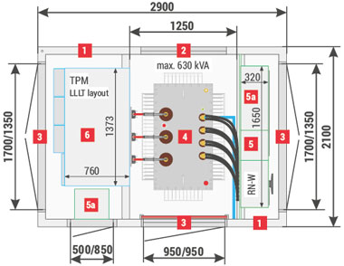
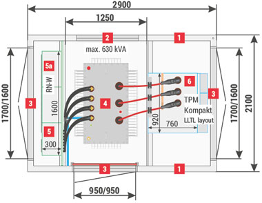
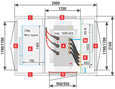
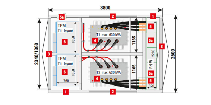
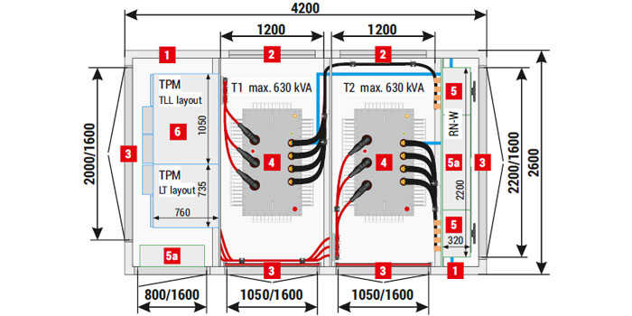
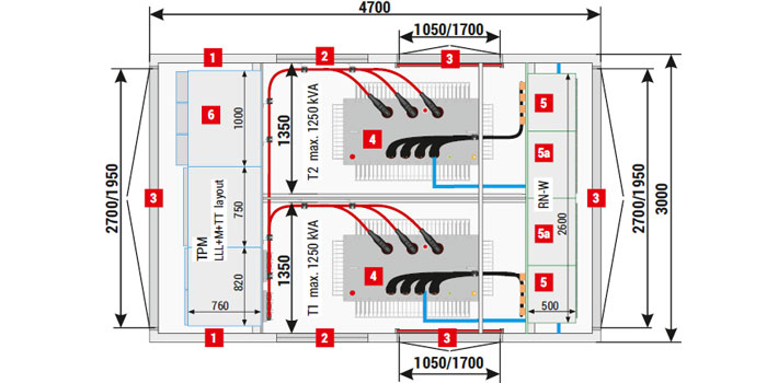
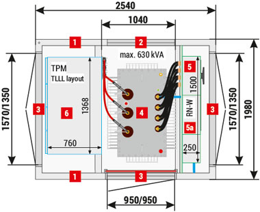
Placement of equipment
Mzb2 (2,54x1,98) 20/630-4"a” (Minibox 20/630)
Mzb2 (2,54x1,98) 20/630-4"b” (Minibox 20/630)
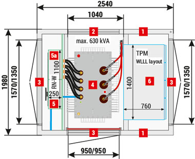
| 1 | Walls, 90 mm thick - standard |
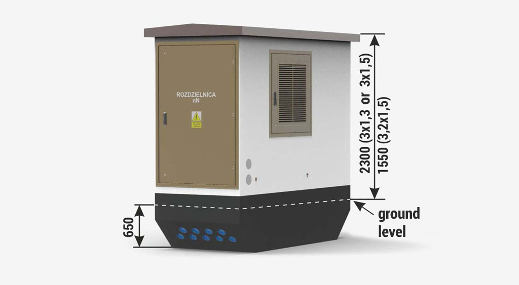
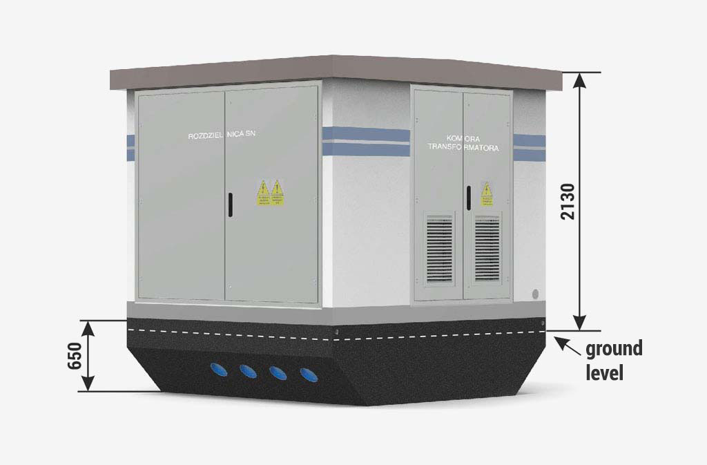
| 2 | Ventilation louvres IP 23D - standard, IP 43 - optional |
| 3 | Doors: solid or with ventilation louvres, IP 23D - standard, IP 43 - optional |
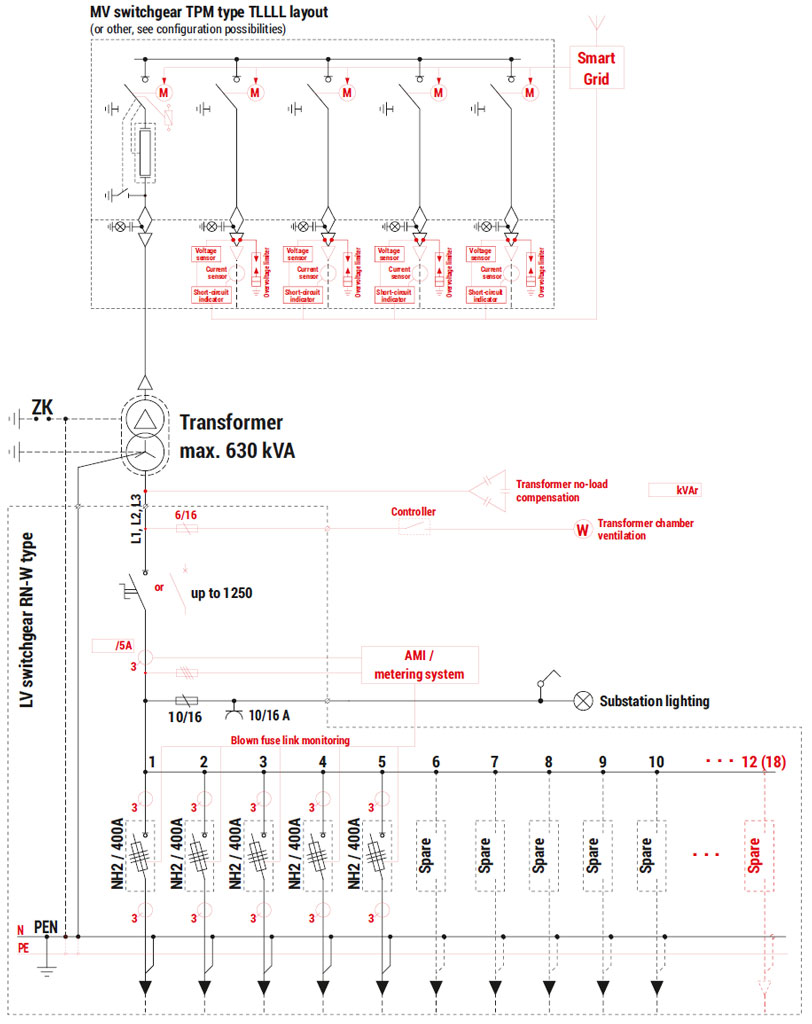
| 4 | Transformer |
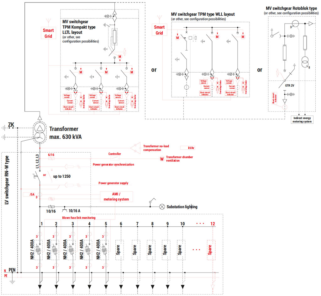
| 5 | LV switchgear |
| 5a | AMI cabinet / Smart Grid / telemetry / auxiliary |
| 6 | MV switchgear |

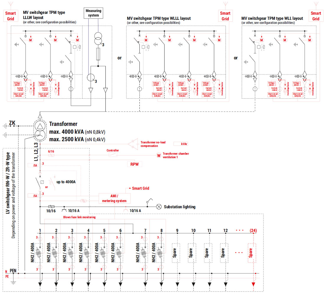
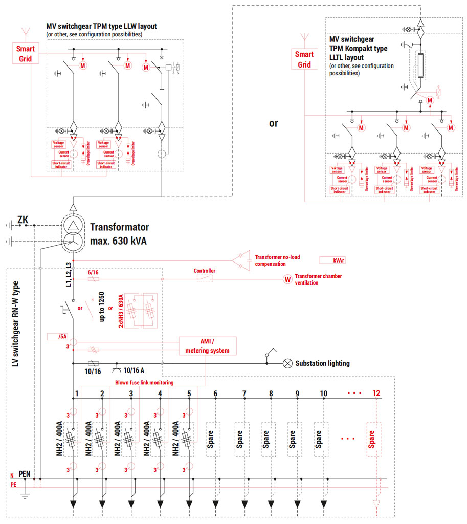
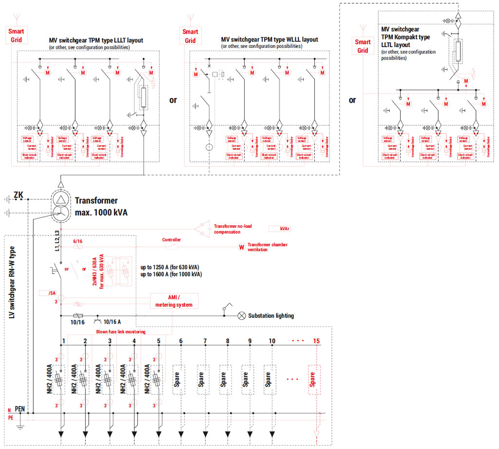
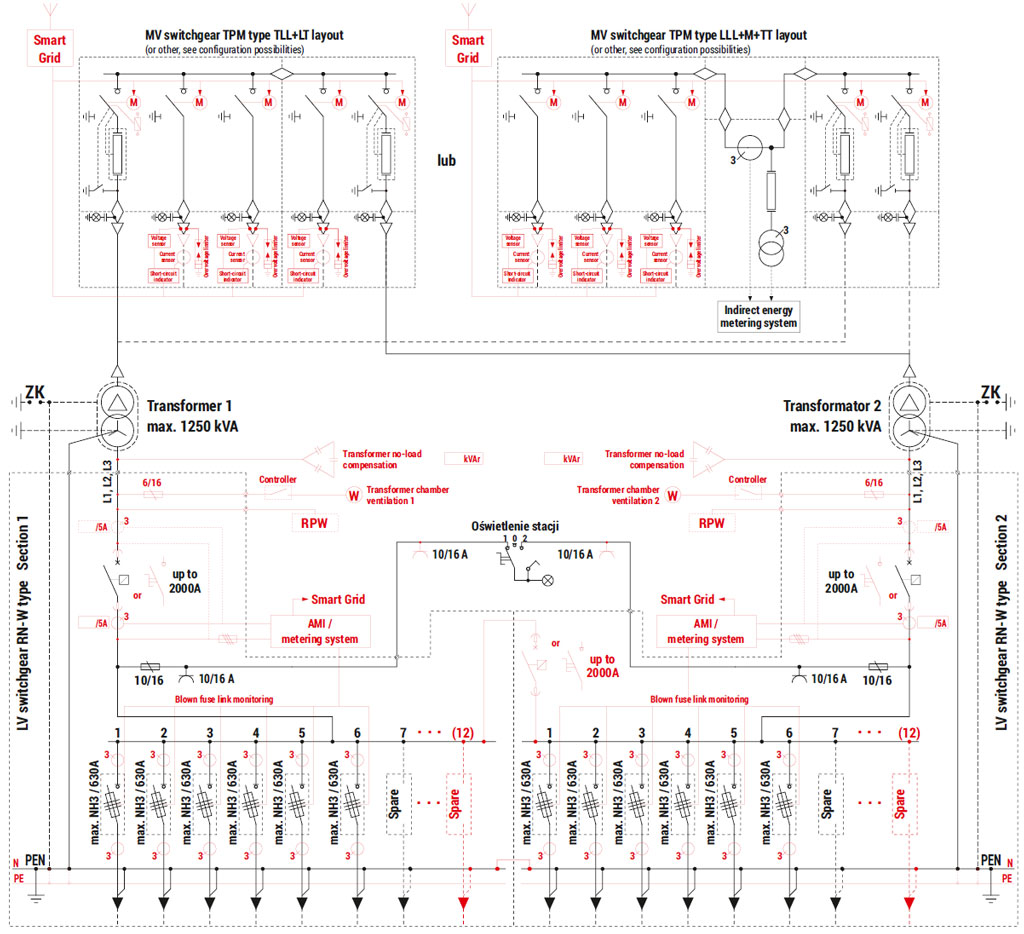
Technical parameters / configuration possibilities
| Masa / Powierzchnia | |
| bryła główna: | 4 800 kg |
| dach betonowy: | 1 800 kg |
| dach metalowy: | 300 kg |
| powierzchnia użytkowa: | 4,15 m2 |
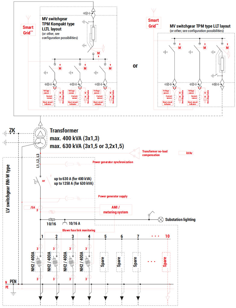
| Technical parameters / configuration possibilities | |||
| Transformer* (4) Maximum power / dimension | 630 kVA / 980 x 1550 x 1850 [mm] | ||
| Internal arc resistance classification | IAC-AB-20 kA-1s | ||
| Enclosure class | 20 | ||
| Electrical parameters of switchgears | MV | LV | |
| Rated voltage | up to 25 kV | up to 0,69 kV | |
| Rated current | 630 A | up to 1250 A | |
| Rated short-time withstand current | up to 25 kA (1s) | up to 25 kA (1s) | |
| Rated peak withstand current | up to 63 kA | up to 55 kA | |
| Switchgear** | Type | Maximum number of bays | |
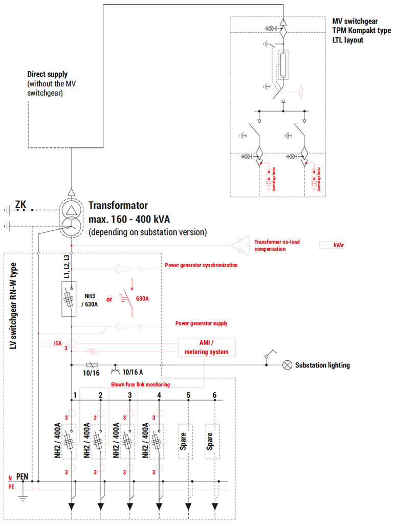
| LV (5) | RN-W | 15 | |
| MV (6) | TPM | 4 (TLLL or WLLL) | |
* Transformer inserted from above, before the roof is attached.
** Detailed selection of switchgears and their equipment is listed in chapters dedicated to individual devices in the catalogue. Example layouts of switchgears and corresponding substation configurations are specified in parentheses. The possibility of installing other types and configurations of switchgears should be arranged every time with the substation manufacturer.