Due to the modular design, it is possible to create a wide range of substation configurations based on standard modules, complex configuration based on MV switchgears (in air or gas insulation) and LV switchgears of our own manufacture.
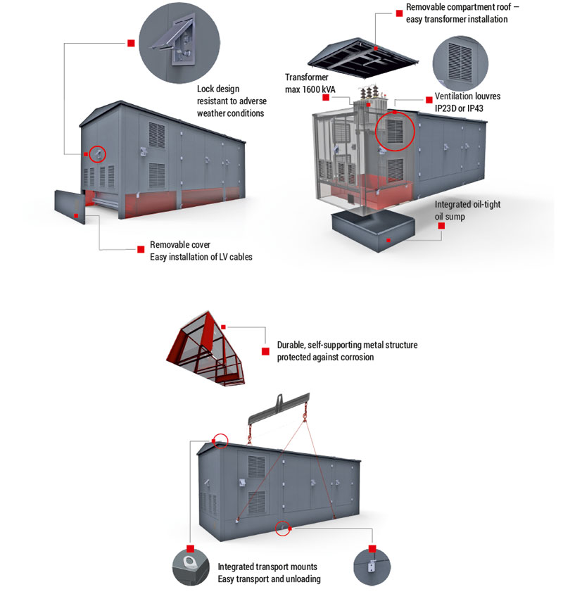
Modular substations are based on a light, self-supporting metal structure. This design enables placement of the station directly on the ground or on previously prepared base, without the need to prepare additional foundations. This shortens the installation time and cost compared to traditional solutions built of brick.
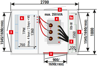
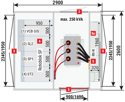
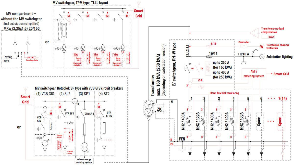
Example configurations of modular substations with TPM and Rotoblok SF type MV switchgears
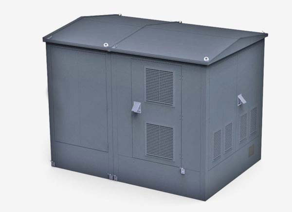
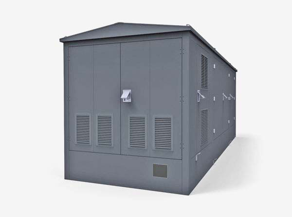
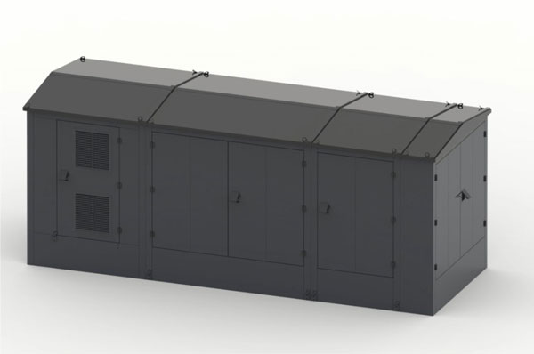
External view
Version with concrete foundations
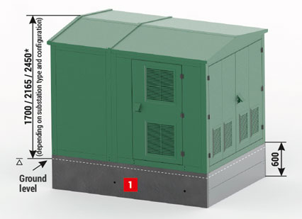
Versions with integrated metal foundations
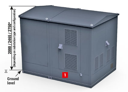
Concrete foundation
Dimensions in accordance with the substation size
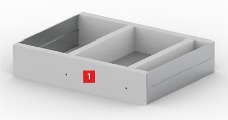
Metal foundation
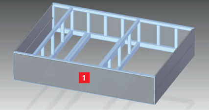
1 - Substation placement part — concrete or metal foundation
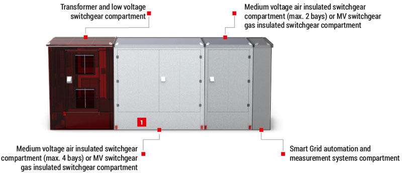
Placement of devices
MRw (2,35x1,6) 20/160 - final substation (simplified)
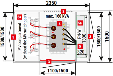
| 2 | Ventilation louvres - optional |
| 3 | Doors: solid or with ventilation louvres, IP 23D - standard, IP 43 or IP 55 - optional |
| 4 | Transformer |
| 5 | LV switchgear |
| 5a | AMI cabinet / telemetry / auxiliary |
| 6 | MV switchgear |
| 6a | MV compartment without the MV switchgear |
MRw (2,7x1,8) 20/250-4
MRw (2,9x2,6) 20/250-4
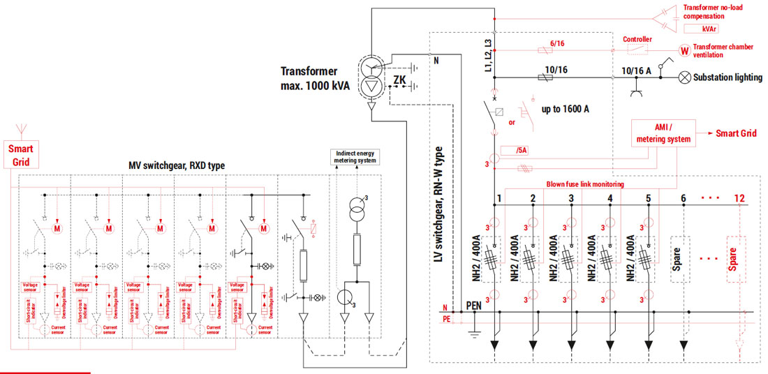
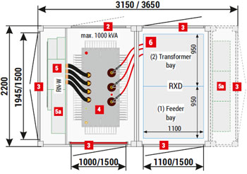
Example configurations of substations with RXD type air insulated switchgears
Placement of devices
MRw configuration no.1 max. 1000 kVA
MRw configuration no.2 max. 1000 kVA
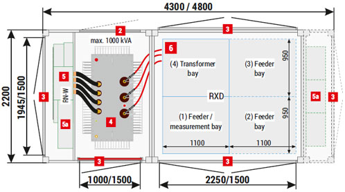
MRw configuration no.3 max. 1000 kVA
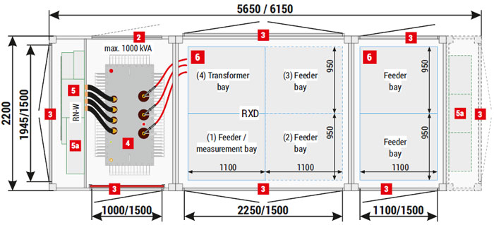
| 2 | Ventilation louvres - optional |
| 3 | Doors: solid or with ventilation louvres IP 23D - standard, IP 43 or IP 55 - optional |
| 4 | Transformer |
| 5 | LV switchgear |
| 5a | AMI cabinet / telemetry / auxiliary |
| 6 | MV switchgear |